SYSTEM FOR REAL-TIME DATA ACQUISITION AND PROCESSING ON A HAIL-FIGHTER AEROPLANE Andreas Bernhardt, Martin Heigl, Martin Versen, Peter Viehhauser, Peter Zentgraf Department of Engineering Sciences, University of Applied Sciences, Rosenheim Hochschulstraße 1, 83024, Rosenheim, Germany phone: + 49 8031 805663, fax: + 49 8031 805658, email:
[email protected] web: www.fh-rosenheim.de
ABSTRACT The System HAILsens implements a device for Real-Time sensor data processing, running on a Texas Instruments Concerto M3 core. An I²C interface is used for sensor communications. Ethernet with UDP on a custom developed three layered frame organisation of sensor data serves as a link to the main system on board of an aeroplane. For backing up the acquired data, all frames are locally stored on an SD Card. To have the possibility of easily checking the current system status, an LCD module and a push-button provide a minimal user interface. 1. INTRODUCTION In Upper Bavaria and also in neighboring regions of Austria, thunderstorms and hail cause vast damages to crops, cars and houses. Hence, there is a nearly hundred year long history of fighting hail with various means and strategies. Today, two aeroplanes are in use which seed clouds with silver-iodide to reduce the grain size of hail and in this way effectively lower the risc of damages. HAILsens is part of a large-scale and popular research project called RO-BERTA. The aim of the project is to raise the overall efficiency of Hail-Fighter operations. This is achieved on the one hand directly by giving the pilot an interactive visualization of meteorologic data provided by the German Weather Service (DWD, Deutscher Wetterdienst). On the other hand, long term empirical studies of acquired data on board of the plane should give a better insight in dynamics and correlations of regional weather phenomena. Acquisition and processing of sensor data is the task of HAILsens [10-14]. There are two main motivations for developing the device. First of all, the custom combination of interfaces together with the desired functionality described in this document could not be found on the market. Furthermore, existing devices with similar specifications are only available for several thousand Euros [8]. The expenses of the HAILsens hardware setup add up to only a few hundred Euros, so, the project's budget could effectively be preserved.
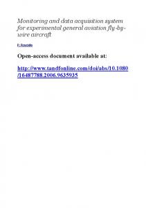
The paper is organized in the following way: Chapter 2 discusses the requirements for HAILsens. It is followed by a short presentation of the main hardware components in chapter 3. The development tools used are listed in chapter 4. Chapter 5 describes the program structure of the main application. After showing the results of the development process in chapter 6, this paper closes with a conclusion and discussion section in chapter 7. 2. SYSTEM REQUIREMENTS The system on board of the twin-engined Partenavia P68 aeroplane is called HAIL (acronym: Hagel-Abwehr in der Luft; Hail Defence in the Air). HAIL consists of the central processing and communication system in the cockpit, HAILscout, HAILacquisition (with additional GPS module and differential pressure measurement) in the nose of the plane and three HAILsens subsystems placed in the wings of the plane and in its tail for sensor data acquisition. Figure 1 shows these main blocks of the system arranged according to their placement within the aeroplane.
Figure 1 - Overview of the aeroplane system HAIL
HAILsens uses a 3-axis motion sensor IC to measure acceleration and rotation. Furthermore, an electronic compass delivers measurements of magnetic field, also on three axes, heading deviation angle from the magnetic north pole as well as pitch and roll angles of the plane relative to horizontal position. Temperature, relative humidity and air pressure are measured with adequate high quality sensor ICs, too. All sensors come with an I²C interface for interactions with their Concerto M3 master. In Figure 2, the block diagram of HAILsens is depicted.
constant sample intervals. An operating system with priority-based, preemptive scheduler allows all critical program components to be executed in separate threads to ensure meeting the given timing requirements, i.e., to have measurement intervals with a 1ms System Tick resolution. The M3 core is running at 100MHz. Another feature of HAILsens is the possibility of checking the proper operation of the sensors and the rough state of the Real-Time application over an LCD. Physical values for each measured quantity are calculated and then sent to the display over its SPI interface. The outputs are triggered by the corresponding measurement tasks (see section 5.2), so the LCD outputs behave in a Real-Time manner as well. Adequate C libraries where created to make controlling the display most comfortable (see section 5.5). However, the default state of the LCD is an inactive one, i.e. the dotmatrix display is empty and the backlight LED is off, because HAILsens will be mounted in the wings and tail during a flight mission and so won't be operated directly by a user. 3. HARDWARE COMPONENTS
Figure 2 - Block diagram of the subsystem HAILsens One challenging part of software development was, to arrange sensor data in the already mentioned three layered communication protocol. In the headers of the different layers, information like time stamps, error tags and reference IDs must be inserted. The calculation and insertion of various checksums and block counts makes the protocol reliable and applicable for synchronization purposes. For communications with the main system HAILscout, an Ethernet interface with User Datagram Protocol (UDP) is applied. Amongst other reasons, favoring Ethernet over CAN, which would be more suitable in this application, is beneficial, because a network of Concerto-based weather stations is planned. The stations will be queried and parameterized over TCP/IP. Thus, Ethernet communication is an appropriate solution. To prevent data loss in case of a of an Ethernet connection failure, a FAT File System (FatFS) on an SD Card is used to store all measurements locally in addition to have data backed up properly. All measurements are taken in Real-Time with fixed acquisition rates, timing constraints and a unique time stamp. Motion data is acquired with a rate of 10Hz, heading information with 5Hz and meteorologic measurements with 1Hz. Every 100ms the 16 bit count stamp is incremented and inserted in the dedicated transmission frame. The achieved deterministic timing behavior is important for the final storage of all measurements in a database on the ground base station, where it will be matched with other data, e.g. GPS position. Further processing like visual evaluation or calculating tendencies will also benefit from
3.1 H52C1 Concerto controlCARD For prototyping and the ease of initial evaluations of the Concerto microcontroller, a Concerto controlCARD with USB Docking Station was chosen for the first development steps (H52C1 Concerto Experimenter Kit, [1]). With the controlCARD, Texas Instruments (TI) provides a fully functional board with SD Card slot and corresponding SPI controller, RJ45 Connector with an Ethernet controller and USB JTAG interface. All signals, microcontroller pins respectively, are comfortably available over a multiple contact strip on the USB Docking Station. Therefore, time has been saved during prototyping, because there was no need to develop an extra PCB. 3.2 Sensors As mentioned before, sensors have been selected with an I²C interface. Amongst a variety of features and configuration options, especially of the MPU-6050 and the HMC6343, the description will only go into details relevant for the project. Specifications like resolution, accuracy or full scale range won't be discussed here. [2]
The MPU-6050 Motion Processing Unit of InvenSense has an embedded 3-axis MEMS gyroscope and a 3-axis MEMS accelerometer. Each of the six values comes as a 16 bit two's complement. A digital low-pass filter of the onboard Digital Motion Processor is applied to avoid fluctuations of measurements.
The 3-axis Compass HMC6343 of Honeywell delivers values for magnetic field, heading pitch and roll. All quantities are provided as 16 bit two's complement.
Temperature (14 bit) and relative air humidity (12 bit) is measured with the SHT21 sensor produced by Sensirion.
The HDI0611 sensor of SensorTechnics delivers a 12 bit value for absolute air pressure.
In addition to the sensor ICs listed above, HAILacquisition (see figure 1) provides modules for GPS data, dynamic pressure and measures the amount of the ejected silveriodide in the two cannons mounted on the wings of the P68.
CCS, the single SYS/BIOS modules can be activated and configured in a user friendly way. [4]
The TI Network Development Kit (NDK) contains comfortable API functions for a variety of Ethernet communication protocols. [5]
SD Card and FatFS drivers offer a convenient way of implementing data storage with a FAT16 file system. 5. PROGRAM STRUCTURE
3.3 Bidirectional Level Shifter
5.1 Hardware Interrupts
To convert the logic HIGH level of the HDI0611 from 5V to the 3.3V of the other bus participants, a voltage level translator is needed. TI offers the TXS0104E for this purpose. The major benefit of the IC is, that no extra signal has to be applied for choosing the conversion direction.
The only explicitly programmed Hardware Interrupt (HWI) handler cares for GPIO interrupts triggered by a pushbutton. To keep the interrupt service routine (ISR) as short as possible, solely a state variable is modified here that controls the activities of the LCD module (see 5.3). In Figure 3, the flowchart of the ISR is shown.
3.4. LCD Module The EA DIP204B -NLW 4x20 LCD module of Electronic Assembly is used for displaying the measured physical quantities directly. Basically, the module consists of a dotmatrix and a display controller which provides an SPI interface 4. DEVELOPMENT TOOLS 4.1 Code Composer Studio Starting software engineering with the help of TI Code Composer Studio Version 4 (CCSv4), integrating SPI and I²C communication went very well. TI's native Real-Time Operating System (RTOS) called SYS/BIOS was used for comfortably configuring multitasking options. When it came to implementing the Ethernet part, several problems arose. The third party API of uIP (see [3]) used in the native TI code examples of controlSUITE caused unreproducible crashes of the program. With standard means of debugging, the problem couldn't be solved in the end, because of the complex call structure of the uIP TCP/IP stack and only a limited amount of available breakpoints in CCS. After requesting help over the E2E Community, members of the TI staff kindly provided a at the time not officially released copy of the Microcontroller Unit Software Development Kit (MCU SDK). Migrating all software parts to CCSv5 and using the MCU SDK components, integrating Ethernet communication and a FatFS on a local SD Card in the controlCARD slot only took little more additional efforts. 4.2 MCU SDK The MCU SDK contains various modules and libraries. Important for solving the above mentioned issues where the following SDK components:
SYS/BIOS is TI's native, scalable RTOS with a small memory footprint. Over the XGCONV tool in
Figure 3 - Flowchart of the HWI handler 5.2 Clock Functions All tasks having to do with sensor queries are encapsulated in Clock Functions. SYS/BIOS offers these functions for a periodic execution of program parts with an initial timing offset. Using Clock Functions, which all have equal priority (lower than HWIs and higher than SWIs) and so can't preempt one another, is the adequate choice for planning the program flow, i.e. setting up the exact measurement cycles for the sensors mentioned in chapter 2.
5.3 Software Interrupts Two Software Interrupt (SWI) handlers, each containing an elaborated state machine, control display activities and the building of frames for UDP transmission and SD Card storage. The interrupts are triggered by a Clock Function with the highest execution rate. Because of sufficiently big remaining time slots, data organisation in the complex three layered frame structure as well as displaying measured quantities will also happen in Real-Time, although the SWIs have lower priority than the Clock Function. 5.4 Tasks One single pure Task function taking part in the Real-Time scheduling cares for Ethernet data transmission and the organisation of SD Card data storage, e.g. for creating appropriate file names, numbers respectively. UDP is an altogether very simple transmission protocol without flow control. Because retransmission queries won't be necessary in the small and well-arranged network on board of the aeroplane, the frames ready to send will just be sent. 5.5 Other Libraries and Helper Functions To keep the software as modular as possible, a number of library functions were created, also for future uses in similar applications. Especially for driving the LCD module, sensor configurations and data acquisition purposes, the large C libraries offer easy-to-use APIs.
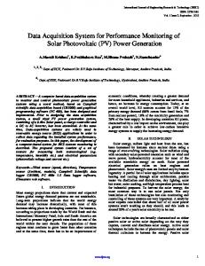
6. BENCHMARKS AND RESULTS Continuous testing accompanied the entire implementation process. When setting up SPI and I²C communications, analysis with an Agilent Technologies oscilloscope DSOX6014A providing a serial bus decoder verified correct data transmission and meeting the relevant protocol specifications. The Hercules SETUP utility, available freely over the Internet (see [6]), enabled parsing the transmitted UDP data frames easily. The created files could be examined with Hex-Editor MX provided by NEXT soft and also available freely for downloading (see [7]). For examining execution times of the different tasks mentioned in chapter 5, means like the Runtime Object Viewer (ROV) or the Exec Graph provided by CCS and SYS/BIOS for Real-Time analysis where used. Furthermore, debug outputs produced via the Systemprintf() function in combination with Clock_getTicks() offered an additional way to evaluate the consumed time slots of the single Real-Time tasks. The System Tick is set to 1ms, because this has a sufficient resolution for the application. The active display outputs, with a processing time smaller than 4ms, are the most time consuming functions in the Real-Time scheduling process. In the end that does not mean any limitation, because the average total CPU load, without considering the background task described in section 5.4, is only about 10%. Figure 4 shows an exemplary M3 core usage of the functions listed in section 5.1 to 5.3. In every line, 600ms are shown to have graphs for an entire measurement cycle of 1000ms. The figure was created with MATLAB after extracting the timing information provided by CCS means.
Figure 4 - Activity of Clock Functions, SWIs and HWI: get data from Motion Sensor (black), get data from Compass Module (grey), get data from Pressure Sensor (blue), trigger Temperature Measurement (orange), get data from Temperature Sensor (red), trigger Humidity Measurement (light green), get data from Humidity Sensor (dark green), arrange dataset in DTP Frame (pink), display data subsets on LCD Module (cyan), Button Interrupt ISR (yellow)
The performance of HAILsens was also evaluated in longterm test runs to test and prove that the system is running stable for more than 24 hours. Based on the fact that HailFighter missions generally take less than three hours, the reliability of the systems seems to be satisfying the requirements, too. The physical quantities measured have not been entirely verified for all sensors until now. Only meteorologic measurements were taken with alternative means to approve the values displayed on the LCD Module. Sophisticated equipment for testing motion and orientation sensor data already exists, but won't be applied before getting HAILsens in a more compact layout (see chapter 7). 7. CONCLUSION AND DISCUSSION The HAILsens prototype has successfully demonstrated the realisation of all system requirements enlisted in chapter 2. After finishing a smaller custom PCB for the device as well as a special housing, HAILsens will finally be mounted into the P68 aeroplane for data acquisition during Hail-Fighter missions. Regarding the integration of HAILsens into the system HAIL, tests showing the correctness of interactions with the other components of the aeroplane system have to follow as well as a series of test flights. Altogether, HAILsens is an automatic unit for Real-Time measurements. In comparison to commercial products with similar functionality, HAILsens is a low cost and high quality device. Furthermore, the rough environment in which the system is operated and the context of a large research project makes HAILsens a contemporary example of a reliable Real-Time application using microcontrollers [8]. The C28 core of the Concerto device has not been touched until now. For future projects, it is planned to program the control side of Concerto using the MATLAB/Simulink Embedded Coder, e.g. for implementing feedback and control loops with complex floating point operations. Linking Embedded Coder Tools with CCS promises acceleration of prototyping with options like Software in the Loop (SIL) or Processor in the Loop (PIL). As the Concerto dual core device has just recently been introduced onto the market, MathWorks is currently not offering full support for the entire device. However, the architecture of the control core is similar to the fully supported Delfino architecture. Therefore, a first evaluation of the described approach is possible and will follow soon [9].
REFERENCES All internet sources have been accessed in May 2012. [1] http://www.ti.com/tool/tmdxdockh52c1, Texas Instruments, website introducing the "H52C1 Concerto Experimenter Kit" [2] M. Frey, "Integration einer Sensorik zur Messung von Umwelparametern in einer Flugzeugnase", Diploma Thesis, Rosenheim, Oct. 2012 [3] http://dunkels.com/adam/ A. Dunkels, Ph.D., website of the "uIP" project [4] http://www.ti.com/tool/sysbios Texas Instruments, website introducing the "SYS/BIOS Real-Time Operating System (RTOS)" [5] http://www.ti.com/tool/ndktcpip Texas Instruments, website introducing the "Network Developers Kit (NDK) with TCP/IP stack" [6] www.hw-group.com/products/hercules/ HW group, website of the "Hercules SETUP utility" [7] http://hexedit.nextsoft.de/ NEXT-Soft, website of the "Hex-Editor MX" [8] http://www.cambridge-aero.com/ CAMBRIDGE Aero Instruments, Homepage [9] http://www.mathworks.de/products/embedded-coder/ MathWorks, website of the "Embedded Coder" [10] http://hochfelln.fh-rosenheim.de/~hoegl/roberta/texte/ Hochschule Rosenheim, Homepage of the Project RO-BERTA [11] http://www.hagelabwehr-rosenheim.de/ Verein zur Erforschung der Wirksamkeit der Hagelbekämpfung im Raum Rosenheim e.V. (Registered Association for Hail Defence, Main sponsor of the Project RO-BERTA), Homepage of the Association for Hail Defence [12] http://www.rfo.de/mediathek/Hochschule_arbeitet _mit_Hochdruck_an_RO_BERTA-16960.html (Review of the Project RO-BERTA in local media) [13] http://www.rfo.de/mediathek/Hochschule_arbeitet _mit_Hochdruck_an_RO_BERTA-16960.html (Review of the Project RO-BERTA in local media) [14] http://www.rosenheim24.de/news/rosenheim-land/ lk-rosenheim/hochschule-rosenheim-hagelabwehrrosenheim-testen-neue-datenverbindung-hagelabwehrrosenheim24-2302761.html (Review of the Project RO-BERTA in local media) [15] http://www.merkur-online.de/lokales/ landkreis-miesbach/heftige-unwetter-bereitenhagelfliegern-probleme-2266608.html (Review of the Project RO-BERTA in local media)