scription to follow, `in connection with the ac companying drawing, in which: '. Fig.
1 is a schematic circuit» diagram of a ..... from human speech to that of a parrot by
merely ... Z600-3200 ... This ls to indicate that the variouschannels can.
May 27, 1941.
H. w. D'uDLl-:Y
2,243,089
SYSTEM FOR THE ARTIFICIAL PRODUCTION 0F VOCAL 0R OTHER SOUNDS Filed May 13, 1939
2,243,089
Patented May 27, 1941
>UNITI-:D STATES PATENT lOFI-‘ICE SYSTEM Fon THE ARTIFICIAL PRODUCTION0F vooAL on OTHER souNDs Homer W. Dudley, Garden'City, N. Y., assignor to Bell Telephone Laboratories, Incorporated, New York, N.`Y., a'corporation of New York
Application May 13, 1-939. Serial No. 273,429A 26 Claims. (Cl. 179-1) ~'I‘he present invention relates to wave trans which it may be desired to produce a controlled mission or control, involving waves of frequency band characteristics, for intelligence transmis sion, sound production or reproduction or other -purposes.
.
.
y
.
change in character between the analyzed wave and the reconstructed wave. '
`
The invention contemplates .speciñcally two general ways of changing the type or character
'I'he invention relates to the genera1 type -of » ` of the'reproduced wave. In accordance with _one wave control or wave production that is disclosed method, the wave used as raw material in re
in my United~States- Patent 2,151,091, granted March 21, 1939, and for its general object it con
constructing the output Wave itself possesses or has imparted to it certain modifications or ychar
templates certain improvements or modifications of the basic system and method therein disclosed.
vof analysis of the original Wave or in such man
acteristics before it is acted upon by the products“
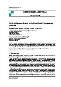
In accordance with the disclosure of my prior ner that it añects the character of the ,recon patent referred to, a wave having the character structed Wave. In accordance with the other istics of speech, for example, may be produced 'mentioned method, a wave of either uniform artificially using as raw material wave energy 15 energy distribution or non-uniform energy varia-. having a frequency distribution which may be tion may be used as raw material, but the fre uniform over a requisitely wide frequencyl range, quency regions chosenfor reconstructing the out and, therefore, lacking in character or intelligi put wave lack exact correspondence with those bility. The wave construction is'accomplished used in the analysis of the original wave and this by modifying such raw material wave energy in results in a translation, change of voice or other conformance with the fundamental pitch and eiîects to be described. These two methods of energy distribution relations which characterize` changing the character of the reproduced speech the speech or other wave to be produced. For or music may be used separately or in conjunc best results the wave energy serving as the raw » tion with each other. . material comprises two types of waves, simulat 25 The nature _and objects of the invention will ing respectively a buzzer-like tone and a hiss or be more fully apparent from> the -detailed de unvoiced wave. An original speech or music wave scription to follow, `in connection with the ac may be analyzed for its fundamental character companying drawing, in which: ' istics `of pitch and energy distribution. In a Fig. 1 is a schematic circuit» diagram of a
complete analyzer-synthesizer system, the 'result 30 complete system according to the invention;
of the analysis is used tol reconstruct the ñnal wave out of the artificially supplied Waves. For a more complete understanding of the systems_and methods involved, reference is made to the patent disclosure. '
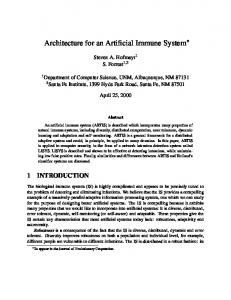
Eig. 24 shows a modiiication which may replace the portion of 'Fig. 1 to the right of andbelow the broken line H-II; and
to be discussed.v
While the system of my 'prior patent is sus ceptible _of many types-of uses and embodiments, one of its aims is to secure faithful transmission and reproduction of speech, music or other Waves,
`
`
~
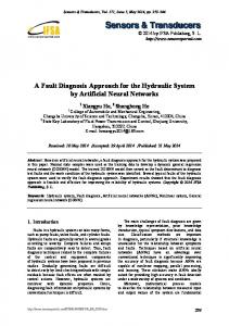
Fig. 3 shows a diagram of frequency relations '
Referring now to the drawing, in Fig. 1, speech or' music currents from line or circuit I energize a frequency pattern control circuit FP and an
amplitude pattern lcontrol circuit AP. 'I'he fre although it is, of course, not limited to this aspect. 40 quency pattern control circuit, which comprises 'I'he present invention may also be used similarly y but one channel FP1 discriminates as to the fre to the system of my prior patent, but the point quency pattern. This discrimination includes of view of the present invention is directed more discrimination -as to the fundamental frequency to securing a -deliberate change of character be when there is one. The amplitude pattern con tween the analyzed Waves and the reconstructed 45 trol circuit branchesv into a number of channels, waves. Such change in character may be de for example, ten channels AP1 to AP1o and de sirable for many purposes, such as rendering termines what amplitude pattern we have. For speech more understandable in the presence of simplicity, channels _AP4 to APs are omitted from noise or because of other conditions making re
the drawing.
ception difficult, or for purposes of imitation, im- r
personation, entertainment, research in speech
The information obtained from the speech analysis eifected in these two circuits FP and
or hearing, voice or musical training or instruc
- AP is in the form of electrical currents which f
tion and kindred purposes.
-»
'
,
can be transmitted through any suitable trans' The invention contemplates in its objects the mitting medium, such for example, as lines Lo to 55 realization of these and any other purposes for Lio, to the receiving or reproducing end of the
2
2,243,089 frequency spectrum of such sounds is, ln
system. This transmitting medium may have a limited frequency range of transmission, of much less Width than the frequency range of the speech signals to be communicated. If desired, it may
general, continuous and devoid of discrete y
components.
’
'
3. Mz‘œed sounds.--F0r these sounds the acoustic energy is derived from both the `above l be a single conductor pair or a radio link, the CFI
_transmission through this medium then being,
sources and the frequency spectrum consists
for example, on a carrier frequency basis in the general fashion shown in my above-mentioned
tinuous spectrum. The frequency pattern
patent.
of discrete components -superposed on a con control channel FP1 is a circuit that ana
l
lyzes speech ,sounds on the basis of the above classification and which, within cer
At the receiving end of the system, in channel FP1 the received waves act on an energy source
of frequencyl patterns FPS so as to cause currents
tain limits, delivers to, a load a wave whose frequency spectrum is of the same class as
of the‘proper frequency pattern to flow from this
that of the speech sound applied to the source, and the received waves in channels APi input of the circuit. ‘ to APio are used to control shaping networks SNr to SNio, respectively, to give the proper The circuit operates so that when no signal amplitude pattern to the power received by these V ‘ or an unvoiced speech sound (Class 2, above)` is networks from the energy source FPS. We- then applied to the input, random noise from a` gas have our reproduction or reconstruction of the filled tube amplifier is supplied to the load. The original speech signal for any further transmis 20 spectrum of such random noise is a continuous
sion in the ordinary manner, or for reproduction of sound by loud-speaker 5.
one and 'so is similar-to that of the source of
acoustic energy in unvoíced sounds but any other
The system as shown uses a 275 cycle total
source with a similar spectrum could =be used.
transmissionband in the transmission medium> When a voice or mixed speech sound (Classes 1 between the transmitting and receiving ends of 25 and 3, above) is applied to the input, the noise the system, that is, in the lines Lo-to Lio. This voltage is removed from the load and a wave of 275 cycle band is on the basis of eleven channels, each of 25 cycle pass-band. Ten of these are for amplitude pattern control and the other one
vthe s_ame fundamental frequency as the 'speech .
is for frequency pattern control. As brought out 30 in my above-mentioned patent, such a system is
sound and any desired frequency spectrum is supplied to the load.
The analyzing circuit of the frequency pattern
control channel FP1, or the portion of this chan adequate for good quality transmission of speech. nel at the sending or analyzing end of the sys The frequency pattern control channel FP1 tem, will first be described. It comprises a de will firstbe described with reference to its ad tector D which may be, for example, a full-wave justment for use in natural reproduction of 35 copper-oxide rectifier, an attenuation discrim speech. It is a. circuit for analyzing and 're ination network’ or so-ca'lled equalizer E1 having producing the frequency spectrum of the source its loss increasing with frequency, a frequency of energy in speech sounds. For speech applied measuring circuit FM and a 25 cycle low-pass to its input from line l 'it delivers an output filter Fao. The speech currents from line l are ‘ wave that has discrete components andis of 40 fed through the rectifier D, which feeds the the same fundamental frequency as the input equalizer E1, which in turn feeds the frequency when a voiced speech sound is applied, and an measuring circuit FM. This frequency measur output Wave with a continuous spectrum when ing circuit may _be any suitable circuit for deliv >>an unvoiced speech sound is applied. It per ering through the low-pass filter Fao a direct cur forms three functions. First, at the transmit rent that depends on the number of reversals ting or analyzing end of the system it derives per second of direction of the voltage wave ap from the speechy signal thefundamental or vocal plied to this circuit and is independent of itsy cord frequency and expresses this as a current, amplitude as long as the amplitude exceeds a the amplitude or magnitude of which is propor certain threshold value. For example, this cir tional to the fundamental frequency. Next, at 50 cuit may have the form shown in Fig. 2, of the receiving or reproducing end of the system Patent 2,183,248 of R. R. Riesz issued Dec. 12, ' it uses this current to control the frequency set 1939. This form is preferred on account of its up by a relaxation oscillator so as to get back a
wave of the- original fundamental frequency, ,
Finally, it provides 55
rich in upper harmonics. for another source of energy at the receiving
being stable and free from singing, free from false operation at high frequencies, positive in action upon application of the input wave, and economical of plate battery power. In order to
end, havinga continuous spectrum, when there have the output current of the frequency meas is no fundamental in the speech. This y"condi .uring` circuit controlled by the fundamental of tion occurs when sounds are unvoiced, as’for the voice, the rectifier D modulates the various example, in Whispering and the unvoiced con 60 harmonics to give a. strong fundamental and the sonants.
-
From the standpoint of the source of acoustic energy the sounds of speech may be divided into three
classes:
'
-
^
1. Voiced sounds-_For these siunds the acoustic energy is derived from the vibration of the Vocal cords and the frequency spectrum is
characterized by discrete components.' 2. Unvoiced
sounds-For
these
sounds
harmonics Aare suppressed by the equalizer E1. The equalizer ma'y be any suitable network hav ing its loss increasing with frequency so as to 65 insure that the fundamental frequency, which
may vary for example from about 80 to some A30() cycles, comes out at a high power level com pared to any upper harmonics that may Ibe
present. The equalizer may practically cut off the 70 transmission abovea frequency' in the neighbor
- acoustic ener'gy is not derived from the vi
hood of 300 cycles, for example. For practical
bration of the vocal cords _but from the
purposes the attenuation discrimination of the
passage of an air stream through a restrict
equalizer purifies the `fundamental tone though
ed apertureor from the sudden stopping or starting of such `a stream of air.
it may vary substantially more than an octave. The 75 The level of the unvoiced sounds must be ad
3
2,248,089 justed. to a value too low to cause operation of
purpose will be described later on) is assumed to
the frequency measuring circuit. If desired, _for
be open.
'
this purpose a voice amplifier G, with its gain adjlßtable, may be provided, for example in the
'I‘he amplitude pattern control channels are circuits which at the transmitting or analyzing channel APi as shown in Fig. 1.` The direct cur- > end of the system measure how much power there» rent delivered by the frequency measuring cir is in the speech signal in chosen small frequency cuit through the low-pass filter Fan may be made bands and transmit this information by control substantially directly proportional to the funda ' currents to the receiving or» reproducing end. mental frequency applied to the frequency pat where the output of the energy source of fre tern control channel from line 1.. quency patterns FFS appearing in circuit I0 is 1 shaped accordingly. For transmitting a speech The direct current ‘delivered by the 'low-pass frequency range from 0 to 2950 cycles, for exam filter Fao which may be substantially directly .proportional to the fundamental frequency ap-` Íple,'the speech bands chosen may be, for in plie'd to the frequency pattern control channel stance, one lband from 0 to 250 cycles and nine from. line I is transmitted-through line Lo to the ' adjacent bands each 300 cycles wide, starting at energy source `of frequency patterns FPS. 'I‘he 250 cycles. These bands are selected by filters latter comprises a relaxation oscillator 40 and a F1 to F1o in the amplitude pattern contr'ol chan noise source 'including gas-filled tube 4I fol nels AP1 to APm, respectively. Thus, of these lowed by switching amplifier 43. amplitude pattern control channels used to trans The Vrelaxation oscillator comprises gas-filled 20 mit information about the amplitude pattern, the tube 60 together with circuit elements as de channel AP1 transmits information about the amplitudes in the speech range 0 to 250 cycles, scribed more fully in the Ries'z patent above re ferred to. This oscillator generates a wave which ~ the channel APs transmits information about the- amplitudesin the speech range 250 to 550 cycles, is rich in harmonics and the fundamental fre quency of which is controlled by the voltage ap the channel APa information about the ampli tudes in the range 550 to 850 cycles, etc. pearing across resistance I2 due to current flow in the line Lo. y Considering channel AP1, for example, the out- ‘ The noise source 42 comprises gas-filled tube put from the 0 to 250 cycle speech band-passv ñl 4I having its grid tied to the cathode and having ter F1 is fed to detector D1, which may be, for suitable resistances in its plate circuit as shown 30 instance, like the detector D. 'I'he syllabic fre together with a plate battery. 'I‘his tube while quencies in the output from the detector are shown as a triode may advantageously be a multi passed through a 25 cycle low-pass filter F31 and grid tube, such as a pentode or tetrode. It is the resulting variable direct current is passed found that this type of circuit produces a con through line L1. This variable direct current is then applied to a biasing resistor B to give a grid tinuous energy spectrum of noise in the audio range. If desired, an equalizer or amplitude bias to a .signal shaping- network or push-pull variable gain amplifier SN1, which accordingly limiter (not shown) may be included between tube 4I and switching amplifier 43 to make the varies its gain in amplifying the waves received output flat over the frequency band. Instead of from the energy source of frequency, patterns the type of noise source shown, a resistance source 40 FPS through 0 to 250 cycle speech band-pass fil of noise may be used as disclosed in the Riesz ter F1', so that the average power in this band of patent referred to. - i Waves varies in accordance with the average pow fThe function of the switching amplifier is to er inthe corresponding band of the speech sig nals. 'I‘he energy from the amplifier SN1 is then - determine whether or not the continuous spec trum of noise is permitted to pass through to the fed through a 0 to 250 cycle speech band-pass fil circuit I4. This is accomplished under control ter F1" tothe speech receiving circuit 4, Where it of currents supplied across the grid resistor I3 .is combined with the outputs from nine other from the control line L0. The bias Voltage on the speech band-pass filters ( of channels AF2 to APml switching amplifier in the absence of any voltage to give a reproduction of the original speech sig drop across resistance I3 is insuflicient to block 50 nal. transmission. When voiced sounds are impressed It will be understood- that in the description on the system the~voltage developed across re thus far the filters F1’ and F1" may have the ' same pass-‘band as filter F1, and that channels sistancev I3 is suflìcient to blocktransmission. Conversely, the initial grid _bias on the relaxa APz to APio may be like APi except as to fre tion oscillator- I6 is sufficiently negative so that quencies involved. However, a modified arrange in the absence of voltage applied across resistance ment in which the pass ranges are not the same will be described later on. I2 the tube will not oscillate. When a voiced In the circuit design it is desirable to have the wave is applied to the frequency measuring cir delay in the frequency pattern> control channel cuit the resulting direct current voltage across resistance I2 is of the right magnitude and sign 60 and in all of the amplitude pattern control chan- . nels the same. ~If the frequency pattern control _to cause the tube to oscillate at some low fre channel _FP1 tends to vhave more inherent delay quency for a weak input current and at higher
frequencies for stronger input current. The equalizer 46 renders all of the harmonic components of the current wave of the relaxation oscillator 40 equal in amplitude. This may be
followed by amplifier 41, if desired.
thanthe amplitude pattern control channels, it
is desirablel to introduce a certain amount of de
ylay in_-the amplitude pattern control circuit AF as is indicated by delay equalizer DE in Fig. 1. . The output of the filters F30 to F46 is unin
telligible, rendering it difficult for unauthorized _ When the switch I5 is closed and the switch 20 persons to tap _the circuit andaiîording a high is in its left-hand position to make contact with 70 degree of secrecy in_either wire'or radio trans terminals I‘I both the noise source and the relaxa- » mission. The waves transmitted,- through the tion oscillator are connected to the synthesizing transmitting medium, such as lines Lo to L10, portion of the system through circuit I0. This directly contain no intelligibility whatever. is in the condition for natural reproduction of 7 Instead of transmitting the currents from ñl
speech or music. In this condition switch S3 (its 75 ters Fao, F31 . . . F40 by separate lines as shown,
-4
2,243,089 -
they may be sent through any other type of chan
as a song with instrumental accompaniment or
nel such as carrier channels or on a time division
as a singing instrument. With switch Sa open, no sounds emerge except when sounds are ap
basis, as in my prior Patents 2,151,091 and 2,098,956 November'- 16, 1937, or in other suitable manner.
plied at M. With switch S3 closed,. pad 30' may be adjusted to give a background
’
simulating instrumental accompaniment. ,With
In the operation of the system, the ten cir
switch I5 open all of- the reconstructed sounds
cuits SNi . . . SNio have their tubes biased so
must come from source 25 or 21 and in the case that‘when no voltage is developed across resist of words spoken into M the articulation is less ance B, the circuits are blocked. 'I‘hus even _though the noise from circuit I4 is impressed on 10 perfectthan if switch I5 is closed. However, the provision .of more filters in the AP lines to fur these circuits it does not get throughthem in the ther subdivide and extend the range would in absence of applied speech currents. crease the fidelity of the sounds at M without When speech or other sounds are directed
against the microphone M in circuit I the sound , the use of the source 42. is analyzed for its fundamental frequency and 15 In discussing the different effects obtainable, it will be convenien-t at this point to adopt terms for the flow of energy in each of the ten fre which distinguish the waves applied to circuit. quency ranges passed by filters F1 . . . F1o in the I0 from those applied to circuit I. It is seen manner described. The currents which represent that the waves applied to circuit I determine these energy flows control the transmission, through the SNi . . . SNio circuits, individually, 20 which of the SN circuits are unblocked andthe extent to which they are individually unblocked. of the waves from the generating system FPS. These waves will be referred to as the spectrum control waves or spectrum since they determine the amplitude pattern or amplitude distribution sound, as determined by the frequency. pattern channel. The result is a reconstructed speech or 25 over the frequency band. The waves introduced sound corresponding to the original. , . at I0 will be called the pitch _control or pitch The present invention contemplates the use of waves since they furnish the actual frequencies
These waves, in turn, are of the type to give a . . voiced sound or of the type to give an unvoiced
other sources of waves for purposes of recon
passing through the SN circuits. For example,
struction of sounds. For example, the drawing
if a talker had a fundamental frequency of 220,
’ shows a phonograph 24 with record 25 and pick 30 the harmonics supplied from oscillator I0 would be multiples of 220 whereas another talker might up 26 as one source of waves. This source is
substituted for the relaxation oscillator 40 when switch 20 is thrown to its right-hand position to open contacts I1 and close contacts I8, and when switch 2| is in position to close contacts 22. At 35 21 is shown a microphone for picking up sound Waves such as speech, music or other sounds, and
may be substituted for the record by shifting
have a fundamental, of, say 190 and the har monies supplied from oscillator 40 would be mul tiples of 190. Or, record 25 or pick-up 21 in' supplying music waves -to circuit I 0 would fix the pitch of the reconstructed speech. In either case the spectrum waves would not affect the
I pitch.
A few of the sound effects obtainable with this switch 2I to its alternate position to. close con tacts 23. The'switch I5 may beeither closed or- 40 system will now be given by way of example, it being understood that these are 'but a few of the open depending on whether _the noise waves are to many possibilities._ be used or not, An adjusted amount’of the waves from the record» 25 or microphone 21 can be - 'I'he pitch may be supplied by one talker at 21 passed directly to the output circuit 4 by closing and the spectrum by a second talker at M. It is switch S3 and adjusting pad 30. _ 45 understood, of course, that both talkers may be from recordings, a suitable reproducer being used 'I'he invention _contemplates use 'of a variable
gain amplifier like SN1 'in the leads -from the microphone 21 and from‘üie reproducer 26 and» connected to channel Lo at terminals X in the
Iin place of microphone M. - The pitch may be supplied from a record, or
chestra or other instrumental music and the spec same way that SNi is connected to channel L1, 50 trum from a talkerat M. In this case the speech so that sounds from the phonograph or micro is automatically made into a song.
phone 21 -are suppressed when only unvoiced sounds are spoken into microphone M. This variable gain amplifier is preferablyadjusted to
The pitch may be> supplied from a singer, ac- -
tual or recorded, and the spectrum from a second singer at M. This presents fan interesting case ' have an abrupt cut-off so that it is unblocked 55 since the singer at M may sing off pitch without and opened for transmission in responsento even affecting the result. Thus a poor singer at M a small amplitude current, in line Lo, the am can be made to appear as a good singer provided plitude modulation occurring principally in the the good singer is supplying the pitch. Also, a SN circuits of the synthesizer. This arrangement talker or singer at M can supply a foreign accent, permits the noise to be applied through switch 60 nasal twang or southern drawl to a good voice, I5 by itself for the unvoiced sounds, the phono such as that of a prima donna. 'I‘his effect might graph sounds being cut off momen-tarily just as be used to change a song sung in one language the relaxation oscillator energy is suppressed into a song sung in a different language. when only unvoiced sounds are to be reproduced, The pitch may be supplied by one singer and -when the system is used for talking. The con 65 the spectrum from a person whispering'at M. trol' of the-noise source from line Lo is unaffected The effects of various animated objects may be by this circuit modification. AThe relaxation os obtained. For example, if any sound of sus cillator is without effect since switch 20 is in its tained character, such as the rustling’of leaves, right-hand position.'
’
Niagara Falls, the roar of surf, machinery noise, bird songs, airplane drone, rainfall, tap dancing,
>Some very interesting and novel effects can be 70 obtained by usev of the substitute source 25 or 21. For instance, if an instrumental rendition of the air of a song `is >used in circuit Ill, and if the4 words of the song are spoken or sung into the
thunder, etc., is used as the pitch and speech is used as the spectrum, the result is >:articulated sound of the type used as the pitch control so that we would then have “talking_leaves,” "the
microphone M, the reconstructed sounds appear 75
voice of raindrops,” etc.«
-
5
ñ2,243,089 Mixed music..-One >voi'ce or one instrument
the analyzer. 'I'his is indicated in Fig. 2 in which
may be used for the pitch control and a second
each of the filters F1' . . . F1o’ and the correspond
Voiceor second instrument for the spectrum with`
A- ing ñlters F1" . . . F1o" have pass ranges different from the corresponding filters F1 . . . F1o. In the
either the same or different tunes in the two cases.v
case of speech this has the eñect of changing the character, for example, from that of a man’s voice to that of a woman’s voice or vice versa. For ex or tremolo effects. _ ' „ ample, the pass ranges of the filters in the synthe In the modification in which a musical selec sizer may be moved upward in the frequency scale tion is sent from the record 25 or pick-up 21 into 10 by 10 per cent as indicated in the following table the synthesizer and words are sung or spoken into in which the total utilized range is assumed to be the microphone M, it might be thought that the greater than that shown in Fig. 1. pitch of the voice would need to correspond with Analyzer' bands Synthesizer bands the tone range of.- the music in >order to produce 0-250 ~ 0-2‘75 ~ the effect of a song. For example, if the music 15 250-550 275-605 were predominately in the high register andthe 550-850 605-935 output waves are to be in the soprano range, lit 850-1 150 935-1265 might bethought that a bass voice at -M would 1 150-1450 _1265-1595 be unable to control the proper SN circuits to 1450-1750 1595-1925 modulate the music suitably. This is found, how 20 1750-2050 1925-2255 ever, not to be the case. If a man’s voice is 2050-2350 y2255--2585 analyzed, for example, a bass voice, it is found 2350-2650 2585-2915 to have frequencies extending over as high a
Variation may be introduced into either or both of the pitch and spectrum waves to secure vibrato
range as those of a soprano voice. For example,
a bass voice contains harmonics of the order of 7,000 cycles or higher. The principal difference between a. man’s voice and a woman’s voice is -in
the fundamental pitch. Probably the main rea son why a woman’s high voice sounds thinner `
> 2650-2950 '
2915-3245
2950-3500
3245-3850
3500-4500
3850-4950
4500-6000
4950-6600
6000-'7500
6600-8250
In addition to changing ythe transmission
than a man’s low voice is that there are fewer 30 ranges of the filters it will ordinarily be desir ableto change the pitch of the voice, which canl harmonics in a given frequency range in the case be done very simply by shifting the movable slider of a woman’s voice, since they are based on a along the resistance I2 of' the relaxation oscil fundamental frequency of about twice that of a lator so as to vary the ratio between the gen man’s voice. There is further the psychology of erated frequency and the amplitude of the fre the lower frequency energy present in the man’s quency control wave. A woman’s voice has a voice. It is apparent, therefore, that a bass voice fundamental frequency about twice as high as a spoken into microphone M would contain the nec man’s voice. 'I‘his means that there are twice essary frequencies to produce control currents in all of the lines L1 . . . L10 and to control the
as many harmonics in a man’s voice of given -
transmission of musical waves, in any part of 40 frequency Aband as in a woman’s voice of the same band. Changing the transmission bands of the spectrum, applied to theV circuit i0. Con the filters alone would produce the effect of a versely, a woman’s voice would also cover a suf woman’s voice of low pitch, such as contralto, if ficient range to actuate all of the synthesizing branches so that songs could be produced in an ‘ register.
v
`
When sounds from the record 25 or microphone 21 are usedfor reconstructing the waves, not only
. the talkerwere a man. By changing the pitch as
well as the pass-bands of the filters a simulation can be obtained. 1f, on the other hand, the
synthesizer filters had their pass-bands shifted downward by, say, 10 per cent, _and the pitch were is the pitch obtained from these sources,but also lowered a suitableramount, the effect would be to enou'fh of _the spectrum is obtained to bring out its salient characteristics, such as the typical 50 translate a woman’s voice into a man’s voice. resonances of a violin or a horn. So long as this
To obtain even better simulation of a Ifemale
spectrum- does not interfere too much with the
spectrum patterns transmitted- through the AP.
voice, for example, measurements >can be made for -all sounds and the needed shifts in response
channels, intelligibility can be passed over the
frequencies provided for, including upward shifts
latter.
-
'
_
Y If it is desired to control only the pitch char-v
at certain frequencies and downward shifts at others. These shifts are made merely by adjust ing the pass ranges of the synthesizer filters. Such changes can be carried out to any desired detail. Similar changes can be made for trans
acteristics by means of a second sound input, the circuit may be used as ñrst described for speech transmission, except that the FP channel is dis connected from microphone M and connected to 60 lating from an adult voice to a child voice or from a second microphone P into which the pitch con -the human voice to speech having the >character trol sounds are directed. This offers the possi istics of animals, either very small animals or large' animals. For example, a parrot’s speech is bility of producing a hybrid voice effect in which not only high pitched but confined to a relatively the second voice controls only the pitch of the narrow frequency range because of the smallness first voice at M. Also a Violin or other means ofthe talking apparatus which determines the may supplya tune to microphone P while a resonance. If an attempt is made to convert talker speaks words into `M in proper cadence. from human speech to that of a parrot by merely The result is a song. Other effects may be ob
tained by varying the method. tuning the talking circuit, it is found that the In the circuit of Fig. 1 _the ñlters appearing in 70 articulation is very poor and that the amplitude any one channeLsuch as L1, are all indicated as having the same pass range', for example, 0 'to 250 cycles per second. The invention contem _ plates, however, the use of filters in the synthe
sizer having different pass-bands from those in
in the resonance region is unduly high.
.
Fig. 3 represents by the series of dashes a,`b, c, etc., the band-pass ranges of the analyzer-filters suitable for human speech\ The dotted curve r
indicates in a general way what the resonance
6
2,243,089
characteristics of a parrot or other small animal may |be. By shifting the pass ranges of the
cause the word yes spoken into the microphone M to emer'geifrom the loud-speaker as no, the
synthesizer ñlters to the frequency positions in dicated at c', d', etc., and making these bands
word we to emerge as you, etc. This suggests the desirability of an automatic control of the
narrower so that a greater number of them can
switching mechanism to produce predetermined types of translation. The currents in the indi
be included within the resonance range of curve
r, and by using suitably higher pitch, the output
vidual lines L1, L2, etc. are in the form of slowly varying direct currents suitable for controlling
speech may be made to appear like that of a
parrot or small animal and enough frequency relays. This olîers the possibility of operating components of the original speech will be utilized 10 relays in the switching mechanism to make pre to permit of good articulation. ' determined changes in the circuit connections of On the other hand, if human speech were to the individual channels under control of currents be made to_ simulate the speech of a wolf, lion or in these channels. The relay 5I is shown con giant, or other large being where the resonances trolled directly from the channel L1 and is sym are broad and low, the pass ranges of the syn 15 bolic of any relay switching mechanism necessary for carrying out the desired switching functions. thesizer filters would need to be shifted down ward in the frequency spectrum and in some For example, relay 5I may be arranged to switch cases at least broadened. In some cases it might channel L1 to one of the other channels leading be necessary to shiftsome of the ranges down to a higher frequency ñlter F2', Fs', etc., so that ward and others upward to meet the require 20 when low frequency energy of sufficient magnitude ments of a double humped resonance curve. appears in channel L1, it causes the production of Measurements may be made in any case to deter mine the type of shift necessary. As a further
higher frequency components in the reconstructed y speech.
Various modifications may be made in
example, the following table indicates the kind the character of the switching and in the manner of shifts that might -be necessary to imitate the 25 of controlling-the relays governing the switclung. speech of a small animal. Where a microphone pick-up has been disclosed it will be obvious that anyother type of device Analyzer bands Synthesizer bands ` for setting up electrical waves having sound wave 0-250~ 250-550
.
0-500~ . 500-1000
550-850 850-1150
1000-1500 1500-1700
1150-1450-
1700-1900
1450-1750 1750-2050
1900-2000 2000-2100'
2050-2350
2100-2200 «
2350-2950
2200-2400
2950-3500 3500-4500
2400-2600 Z600-3200
4500-6000 l
3200-4500
6000,-7500 o
4500-6000
characteristics is contemplated,l including record
ao
reproducers, photocells, induction, dynamic,.capacitive pick-up, etc. Likewise, in place of_ re producing the sounds as at 5, they may be re corded, broadcast, transmitted over lines or uti
'lized otherwise. All types of records are con 35 templated including film, disc, etc. . 'I'he invention offers valuable possibilities 1n
re-recording. For instance, if a record is played into microphone M and if the output energy in circuit lis used to 'make another record, the
40 A translation from the ilrst to the second record can be modified in a wide variety >of ways., by use of
the pitch microphone P, the microphone 21, or The nature of the egects pro
Various other effects may be obtained by con _ trolling the spectrum with or Without controlling
' the record 25.
the pitch.
For example, a bass voice may be duced has been discussed above. In talking translated to soprano and' vice versa. Thus 45 movies, these possibilities may sometimes save a soprano singer of great musical ability would retakes, or may be used variously, as in a series be enabled to sing in the bass register or some of steps, to work up the desired type of ñnal sound other register with the same characteristic record. ' -The shifting of the pass ranges of the recon 50 In Fig. 2 the control 'channels are indicated as structing filters relative to the analyzer ñlters being carried through a switching mechanism may be used along with the alternative sources of quality.
'
.
.
designated merely by the box 50 in the drawing.
pitch control waves 25, 21, etc. to secure desired
This ls to indicate that the variouschannels can
effects.
.
be interchanged at will by the switching mecha nism. For example, incoming channel I can be
It is recognized that the system disclosed herein is susceptible of wide Variation and modification
connected to outgoing channel 9 or any incoming channel can be connected to any outgoing channel
of an obvious nature in view of. the examples given. All such variations and modifications are
by means of the switching mechanism, Some in teresting effects are possible by this means. For
» intended to be protected by this application.
phone M it is heard from the loud-speaker as the
ing and the scope of the invention is deñned in the claims which follow.
60 Moreover, the -various examples, Circuît details' example, if channels I, 2 . . . I0 are active and frequency ranges and sound effects disclosedare the sound e as in meet is spoken into the micro to be construed as illustrative rathervthan limit
' same sound.
With only channels I and 9 oper
ative the sound remains practically the same.
If, . _
however, channel 8 is disabled and channel I from the analyzer connected to channel 2 in the syn thesizer, then the sound e _spoken into the micro phone istransformed into the sound o as in note
from the loud-slpëakerrjyith channel | going to channel 3 the sound become/Eolas in not and with channels I and 9 going to'3 andÈ-rëspectively, the sound becomes aw as in haw. It is actually - possible, by manipulating the switching mecha
nism, including the shifting of energy sources, to
What is claimed is: _
.
1. In combination, a source of music-represent ing waves, a source of speech waves, means to de rive from each of a, plurality of frequency sub
divisions of the speech waves‘an index of the energy content of such frequency Subdivision vary ing with time, means to-~modulate said music representing waves in a plurality of ‘circuits in accordance with said indices, and means to trans late the resulting modulated wave energy into soundl energy.
7
2,243,089 2. The method comprising subdividingy a sound
cies'comprised of a .fundamental frequency 'and
representing wave into a number of 1- relatively
harmonics thereof, means causing the funda
narrow frequency bands, subdividing a second wave of band characteristics into a corresponding number of frequency bands certain of which are of different band width from the corresponding bands of the first wave, deriving an index of the energy content of each of the subdivided bands of the first wave, and controlling transmission of each of the subdivided bands of the second l0
`mental frequency of the generated Wavesto be differentfrom the fundamental frequency of said speech waves but definitely related thereto,
means producing sounds from said generated
mentioned wave in accordance with a different
waves, and means controlled by said several en ergy rates for determining the eifectiveness of said means in producing sound from each of sev eral frequency regions of said generated waves, different in frequency from the regions of _the
one of said indices.
speech waves used to determine said energy
l
'
3. The method of producing vocal modulation of a musical wave comprising subdividing into
rates.
\
»
`
»
8. ,In combination, means for producing the elîect of a small animal talking under control of human speech, comprising means for generating acousticfrequency waves extending over the rel
narrow frequency bands the energy spectra of both the vocal wave and the musical wave, deriv
ing an index of the energy content, varying with
time, of each of the subdivided vocal wave bands, ì ' atively narrow frequency range appropriate to
said animal, means for subdividing said Waves
reproducing sound from the subdivided bands of the musical waves, and controlling the sound re
20 into a number of narrow bands, means for sub
dividing the human speech waves into a_.correspending number of narrow bands, means deter mining the energy rate of each of said latter _dex so derived. » bands, and a plurality of means controlled indi 4.A The method of reproducing speech with changed voice comprising analyzing the speech - vidually in accordance with the energy rate of said individual bands for producing sound in ac waves to determine their energy content in each -cordance with each of said_bands of said gen-' of a plurality of distinct frequency regions, gen erated waves. _ erating waves having a frequency band extend 9. In combination, means for producing the ing over the range of the sounds to be produced, and varying the energy content of each of a plu 30' effect of a giant or large animal talking under control of human speech comprising means for rality of distinct frequency regions of said gener generating audio frequency waves extending ated waves in accordance with the energy con over the relatively great frequency range appro tent of a respective region of the analyzed waves, priate to said giant or large animal, means for the distinct frequency regions of the generated waves so controlled being displaced in frequency 35 subdividing said generated waves into a number of relatively narrow bands, means for subdivid with respect to the respective distinct frequency . ing the human speech waves into a correspond regions of the analyzed waves. ing number of narrow bands, means determining5. The method of reproducing speech with the energy pattern of each of _said latter bands, changed voice comprising analyzing the speech
production from each such subdivided band of the musical waves in accordance with a respective in
waves .to determine their energy content;l in each 40 and a plurality of means controlled individually
of a plurality of distinct frequency regions, gen erating waves having a frequency band extend ing over the rangei of the sounds to be produced, and varying the energy content of each of a plu
rality of distinct frequency regions of said gen erated waves in accordance with the energy con
tent of a respective region of the analyzed waves,
the distinct frequency regions of the generated waves so controlled being of respectively differ ent frequency width from the corresponding dis
tinct frequency regions of the analyzed speech. 6. In combination, a source of waves of a range `
of acoustic frequencies, a second source of waves
of a range' of acoustic frequencies, a set of ñlters for subdividing the waves from the ñrst source -
into relatively narrow frequency bands, a set of filters for subdividing the waves from the second source into a corresponding number of relatively
in accordance with the energy pattern of said in
dividual bands for producing sound in accord ance with each of said bands of generated waves.
10. The combination according to claim-8 in cluding means to Aderive the fundamental fre quency lof said speech waves, and means to con trol the frequency of _the generated waves
thereby. 11. The combination according to claim 9 in cluding means to derive the fundamental fre quency of said speech waves, and means to con trol the frequency of the lgenerated waves thereby.
,
`
~
'
12. A system comprising a plurality of wave transmission channels for respectively transmit ting subbands of a frequency band of waves that represents a voice wave, means for producing a.
complex tone having its fundamental frequency
in controlled relation to that of said voice wave in width from the corresponding bands into which 60 but having the relative amplitudes of its com ' ponents independent of _the relative amplitudes the waves from the ñrst source are divided, means of the componentsyof said voice wave, analyzing determining the energy content of each of the circuits responsive to waves from said channels subdivided bands from said ñrst source, means for determining the energy flow, varyingin time, arranged to respond tothe waves of the 'subdi in each of said subbands, means controlled by vided bands from said second source, and means said analyzing circuits for producing from the for controlling the response of said second means energy of said complex tone a similitude of said to each of said subdivided bands from said sec energy, varying in time, in said subbands, and ond source in accordance Swith the energy con
- narrow frequency bands certain of which differ
tent of the corresponding subdivided band from said flrst source. ç/ '7. In combination, means for/analyzing speech
means for interchanging the control between in dividuall analyzing circuits and the meansv for producing said similitude of said energy in said
Waves to determine their fund mental frequency and their energy rate in each of a number of -frequency regions, means for generating waves >
means controlled by said voice wave for actu
extending overa wide range of acoustic fIeQuen-.~ .1
ating said means for interchanging said control.
subbands.
>
‘
13. A system according to claim 12 including'
8
'
2,243,089
14. In combination, a source of wave energy of band characteristic, a plurality of transmis sion control means operative at different fre
ing subband of said other voice wave and com bining the effects of the subbands of said musi ~ cal wave whose amplitudes are so controlled.
19. The method of enabling~ a speaker to change his voice comprising analyzing his voice
quency regions within said band, means actuat . ing one of said control means in accordance
wave to determine -itsv fundamental frequency and the energy rate in each of a number 0f rela
with voice energy in a low frequency part of the voice range to control transmission of low fre
tively narrow frequency subbands, generating4
quency waves from said source, means actuating another of said control means in accordance
waves coveringv the speech range under control
with an intermediate range of .voice energy to 10 of said fundamental frequency, subdividinglsaid generated waves into a corresponding number control transmission of waves ofI intermediate _of relatively narrow frequency subbands certain frequency from said source, means actuating an of which differ in band width from the corre other of said control means in accordance with
sponding frequency subbands of said voice wave, a high frequencyy range of voice energy to con trol -transmissionof waves of high frequency 15 controlling the amplitudes of the waves in the -various subbands of said generated waves in ac from said source, means making certain ofI the cordance with the energy rate of the correspond- ' frequency ranges whose transmission is con ing subband of said voice _wave and .combining trolled by said several transmission control the effects of the waves of said subbands whose means different in width from the corresponding ranges of said voice wave, and means for com 20 amplitudes are so controlled. 20; The method according to claim 19 com bining theeffects of the transmitted ranges. . prising generating said band of waves from a 15. The method of simulating the effect of a fundamental frequency dependent on the funda talking object which gives off a characteristic mental frequency of said voice wave but different sound of its own, such as a-waterfall, machine,
etc., which comprises subdividlng said charac-~ 25 teristic sound into a number of relatively- narrow frequency subbands, subdividlng speech waves intoa corresponding number of relatively narrow frequency subbands, utilizing the energy in Ieach ' of said subbands of the speech waves to control 30 transmission of the corresponding subbands of
therefrom.
.
_
21. 'I'he method according to claim "19 com
prising making certain of the subbands of the generated 'waves vof different band Width from the corresponding subbands of said voice wave and shifted in frequency with respect thereto. 22. Means for producing the effect of a singing;
said characteristic sound, and making certain of the frequency subbands of saidcharacteristic wave of respectivelyl different width from the
musical instrument comprising means for pro ducing waves characteristic' of such instrument
relatively narrow frequency subbands, subdivid
the waves in each of said subbands to a respec
ing speech waves into a corresponding number` of relatively narrow frequency subbands, con
tive one of said control devices for transmission therethrough, means causing waves to flow in
and representing a musical selection, an input corresponding subbands of said speech wave. 35 circuit, an output circuit, a plurality of trans mission control devices connected in parallel 16. The method of simulating the effect of a paths between said input circuit and said output talking image or cartoon comprising vsupplying a circuit, means for 'subdividlng said characteristic frequency band of waves appropriate in pitch wave on a frequency basis into a corresponding and `band width to said image or cartoon, sub vdividing said band> of waves linto a number of 40 plurality of frequency subbands, means to apply
trolling thel amplitude of each of said frequency
said input circuit representing words spoken in
subbands of said first wave in accordance with 45 cadence with said musical selection, means sub dividing said latter waves into a plurality of fre the energy in each of said subbands of said voice quency subbands, means to determine the- energy wave and >combining the effects of the energies of the subbands of‘said voice wave after such 4characteristic of each of said latter subbands, and means to control the transmission of the control. 17. The'method of producing the effect of a 50 first-mentioned Waves through each vof said transmission control devices in accordance with singing musical instrument comprising taking the energy characteristic of a corresponding one the characteristic wave given oil! by said instru of said subbands representing said spoken words. _ment in the form of a musical selection, sub 23. In a sound producing system, means to dividingl said wave into relatively narrow fre quency subbands, subdividlng a voice wave into 55 produce waves of the frequency range of sounds to be produced, based upon a fundamental fre a corresponding number of relatively narrow fre quency, means comprising a speech input cir quency subbands, determining the energy rate in cuit for speech waves from one wave source to each of said frequency sub ands in said voice control the amplitude relations throughout said wave, controlling the ampli ude of the waves in
eachÁ of the subbands o_f said musical wave in 60 band in accordance with the characteristic en- , ergy rates of _speech at corresponding frequen accordance with the energy rate- of the corre cies of the speech band, and means comprising sponding subband of said voice wave and com ~a second speech input circuit for` speech waves ~ bining the eilîects of the subbands of said musi cal wave whose amplitudes are so controlled.
from another wave source to control said funda
subdividlng another- voice wave into a corre
cuit, a. source of complex tone waves based on a
18. The method of producing sound effects 65 mental frequency independently of said first speech wave source. . comprising taking thel voice of a singer in the 24. In a sound system, two vinput circuits for form of a musical selection, subdividlng said sound-representing waves, a common output cir wave into relatively narrow frequency subbands,
sponding number of relatively narrow frequency 70 fundamental frequency, means for transmitting waves from said source into said output circuit, subbands, determining the energy flow in each of said _frequency subbands of' said other voice
a plurality of amplitude patternv control chan
- wave,ìcontrolling the amplitude of the waves in
nels for exercising control of the waves so trans mitted in each of a number of frequency regions
each of the subbands of saidmusical'wavein ac
cordance with the energy now of the correspond
75 in accordance with frequency regions of the
2,243,089 sound-representing waves in one of said input circuits and a pitch control circuit for controlling
said fundamental frequency in accordance with~ other sound-representing'waves in said other input circuit.
»
25. A system comprising a, plurality of chan
nels for transmitting energy having syllabic time rates of change in the channels, respectively, a source of waves having a sound spectrum the relative amplitudes of the components of which are independent of the relative amplitudes of the components of said transmitted energy, means controlled by the energy in said channels
for varying at said rates, respectively, the energy in diñerent frequency regions of Waves from said source, and switching means for inter changing said channels in their control'of the energy in said diiïerent frequency regions.
9
26. The method of re-recording comprising re producing sound-representing waves from a first record, subdividing said waves on a'frequency basis into narrow bands, generating waves cov ering a. sound range of frequencies, producing a second record from said generated ìwaves, con ' trolling the -amplitudes of the components of the generated waves in diiîerent frequency regions in accordance with the energy ñow in respective
bands of’said subdivided waves, and controlling the pitch of the generated waves independently of said reproduced waves from said first record -in order to eiîect controlled changes in the re recording.
-
,
HOMER ’W. DUDLEY.