The purpose of testing is to show that the product under test has bugs. In order to ... Analysis of paths running in parallel through a set of sequential programs ...
Systematic testing of parallel programs Henryk Krawczyk, Bogdan Wiszniewski Faculty of Electronics, Technical University of Gdansk, ul.Narutowicza 11/12, 80-952 Gdansk, Poland
Abstract The paper presents a new structural model of parallel software de ned as a graph
consisting of interconnected sequential modules. This representation facilitates the testing process, because the number of cases to deal with during the test is much lower than with the use of traditional owgraph representations. We propose a systematic testing procedure based on this new model. Our procedure allows to de ne a testing scenario based on the concept of a test window. Various testing scenarios may be de ned for windows, with regard to speci c classes of errors, testing strategies, internal system state and external environment settings. A tool supporting this procedure is currently under development for the European Copernicus SEPP project [13]; basic functions, structure and principles of this tool are brie y speci ed and discussed.
Keywords: parallel programming models, testing scenarios, test data generation, program
testing tools.
1. Introduction
Testing provides a natural mechanism for exploring operational behavior of a software product. The purpose of testing is to show that the product under test has bugs. In order to achieve that goal within the assumed time and budget it is necessary to carefully plan and systematically execute a set of required tests. Beizer [1] indicates the need for distinguishing three models serving that purpose: a model of the environment, a model of the program, and a model of the expected errors. In this paper we assume the environment to be a set of distinct and logically separated sequential programs running in parallel [2, 3]; we model a parallel program by a multi- owgraph, where each individual component program is represented by it's control ow graph [4], and use the generalized Howden's model of errors based on the notion of a program path [5]. A traditional model for structural testing, i.e., a program owgraph, represents a single (sequential) control ow. Analysis of paths running in parallel through a set of sequential programs requires introducing a concept of the multiple control ow. We will model such a multiple ow by a set of independent control ow tokens; a single token progresses through the related individual component owgraph and (possibly) interacts with other control ow tokens progressing through their respective owgraphs. Based on this model we will be able to build upon the traditional model of a path going through a sequential owgraph. Below we brie y outline the traditional model of path analysis of sequential programs and path related errors. We will identify two problems of path analysis that are speci c for a set of sequential programs running in parallel and interacting with other programs; they determine 1
two additional classes of errors that are needed to extend the path oriented Howden's model. In Section 2 we will introduce the multi- owgraph model of parallel programs, capable of representing multiple control ow tokens progressing through control ow graphs of their respective processes and interacting with one another. This path oriented representation is useful for two reasons. One is that humans tend to view program execution as a sequence of actions or interprocess communications; the notion of a program path re ects this intuitive understanding. Another reason is that structural testing models developed for sequential programs have resulted in a number of techniques that have been e�ectively implemented in a form of testing tools [6, 7, 10, 12]. It will be argued that multi- owgraphs enable path analysis with the use of traditional techniques developed for sequential programs. In Section 3 we will discuss suitability of a multi- owgraph for structural testing. The concept of a test window developed for our structural model will help us to solve problems involving observability, reproducibility, the "probe e�ect", and visualization, typically associated with testing and debugging tools for parallel software [9]. Based on the notion of test windows we will introduce the concept of test scenarios and outline a generic procedure for systematic testing. In Section 4 we will present the basic functional structure of our tool, being currently developed for the European research project Copernicus SEPP (Software Engineering for Parallel Processing) [13].
1.1. Classes of path errors
Consider a sequential (component) program P computing function C in input variables forming a set X =fxi ji =1,...,k g. The set Xk of k -vectors contains all possible combinations of values that input variables can ever assume. Program domain D �Xk is a set of all k -vectors accepted by P , i.e., D=dom (C ). Path analysis of a sequential program P is based on it's control ow graph [4] de ned as a quadruple P= (Q ,A,s ,e ), where Q is a nite set of vertices, A is a nite set of arcs, and s , e are distinguished start and end vertices. Each arc (a ,b )2A, where a ,b 2Q is labeled by a symbol gab representing either a program statement or a predicate. A path p from vertex a to vertex b is a sequence of vertices p= (q 0 q 1...qj), a=q 0 , b=qj, such that for i =0,...,j -1 each (qi ,qi+1 )2A. If a=s and b=e , then path p is called a program path . The path computation C (p ) is a function in Xk computed by the sequence of respective assignment expressions along p . The path condition is a conjunction of all respective predicates along p ; this conjunction describes path domain D (p ) being a subset of D . With this interpretation one can represent program P as a (possibly in nite) set P= fpig of program S paths such that C = fC (p )g and D = D(p ), where i = 1; 2; :::. Given the variety of alternative programming constructs it is hard to predict for an arbitrary program P what exactly it's correct version should look like. Nevertheless, it seems reasonable to consider any program P under test to be either correct or to constitute a small deviation from a hypothetical correct program P [5]. The correct program P is in fact a target form of P that a programmer intends to reach by repeatedly testing and eliminating from P all bugs being detected during tests. The exact statement on what constitutes the "deviations" of P from P is strongly in uenced by the underlying program model and the applied testing strategy. Howden has formalized the concept of "deviations" of P from it's target (correct) version P based on the notion of paths by assuming an isomorphism (a 1-1 correspondence) between sets P =fpi j1=1,2,...g and P =fpi ji =1,2,...g and de ned: i
i
i
0
0
0
0
0
0
2
1)
a computation error , which occurs in P if for all pairs of paths (pi,pi ) such that D (pi )=D (pi ) there is a pair (pk,pk) for which C (pk)6=C (pk), 0
0
2)
0
0
a domain error , which occurs in P if for all pairs of paths (pi,pi ) such that C (pi)=C (pi), there is a pair (pk,pk) for which D (pk )6=D (pk). 0
0
0
0
If there is an isomorphism between paths of P and only a subset of paths of P Howden has also de ned: 0
3)
a subcase error , which occurs in P if for all pairs of paths (pi ,pi), C (pi)=C (pi) and D (pi )�D (pi ). 0
0
0
Computation errors occur in programs with correctly placed and evaluated decision statements, but with some wrong (or missing) assignment expressions along some paths. Domain errors occur whenever predicates in existing control statements are wrong or evaluated incorrectly. Note that a computation error along a path that occurs before a predicate evaluation may result in a domain error in that path. Finally, a subcase error occurs along a path with a missing decision statement. The kind of isomorphism between paths of P and P assumed by Howden captures the problem of systematic selection and execution of paths being selected from the sequential program structural model provided by it's control ow graph. Given any program P this method requires choosing data elements from input domain D in order to follow (exercise) each path pi 2P . We call each data element selected from D a test point , while each path is considered to be a test case . Extensions needed to utilize Howden's classi cation of path errors with regard to sets of sequential programs (processes) running in parallel have to address the issues of independent timing and synchronization of such programs. Two new classes de ned below generalize the classic sequential model of path errors to include communication and synchronization errors in parallel programs. The following class of errors deals with the fact that more than one path may exist in P for the same test point: 0
4)
an observability error occurs in component program P if for some path pi 2P there exists another path pj 2P such that D (pi )=D (pj ) and C (pi)6=C (pj).
Observability error is inherent in a testing environment, not in a program being tested, therefore it's de nition does not involve paths from P . Observability error occurs when a tester cannot distinguish between potentially di�erent behaviors of a program running in parallel with other programs because path representations being used are at the level of detail that is insu�cient to correctly evaluate test results. This error occurs when a tester exercising a path of some component process may fail to observe the interacting communication actions of another processes a�ecting that path. If these actions involve data transfers test results are invalid. Another class of errors addresses the fact that actions of some process may randomly in uence the ability of another process to execute it's own actions. Any path in P may therefore 0
3
start execution for some input data and later fail to proceed beyond some point: 5)
a locking error occurs in P for some program path p 2P , where p =q 0 q 1 ...qj, if there exists vertex qi in p such that subpath ps =q 0q 1 ...qi has non-empty path domain D (ps ), all it's outgoing arcs are labeled with predicates, and all these predicates evaluate to false for some element of D (ps ).
Note, that this de nition does not involve paths from P , as a locking error constitutes an obvious anomaly in the control ow of the component program being tested. A locking error never occurs in sequential program P which does not communicate with other programs. If a tester selects a speci c test point from input domain D of such a sequential program then there is always some path p 2P which can be followed for this test point and which has a true path condition. This property does not hold for a sequential program that can communicate with other sequential programs running in parallel, since the other programs may dynamically change conditions controlling this program statements. 0
2. A multi- owgraph
A multi- owgraph provides a structural representation that enables path analysis of a parallel program in a similar way as the ordinary owgraph enables such an analysis of a sequential program. A key feature of a multi- owgraph is that it allows for a number of independent control ow tokens. In this sense it is similar to the Petri net model, as it can capture inherent parallelism of multiple control ows. On the other hand, it is less abstract than Petri nets, since owgraphs of individual component programs can be directly represented by the multi owgraph structures. A multi- owgraph G(N,A) consists of nodes N connected by directed arcs A. A node of a multi- owgraph is a special object representing a single program statement or a group of statements, including statements from di�erent component programs. An arc represents a control
ow between individual statements of the same process. Owing to this, a multi- owgraph is a special set of component sequential owgraphs, where each owgraph consists of arcs and vertices as de ned before, but vertices of individual owgraphs are contained within multi owgraph nodes. Consider an example representation of a multi- owgraph in a draft form given in Figure 10; for simplicity we have skipped individual statements of component programs contained within nodes, represented by boxes. Note, that this example uses in general three types of nodes: simple nodes, containing statements from just one component process, nodes involved in creating new processes, and nodes containing statements from several processes. We will specify these types of nodes throughout the rest of this Section.
2.1. Simple nodes
Consider rst simple nodes corresponding to decision and assignment statements, as shown in Figure 1; by L, and �L we denote conditional, and respectively by E , assignment expressions. Either node in Figure 1 has a single entry point at which a single control ow token can arrive, and one or more exit points at which that single token can leave. Upon exiting, a control
ow token evaluates expressions at all respective exits. There may be at most one outgoing arc from each exit point. If a simple node has no outgoing arcs at some exit point the token is 4
b) assigment node
a) decision node
L
E
~L
Figure 1: Nodes with single control ows b) fork
a) parallel block
... E
E
E1 ... En
Figure 2: Nodes creating multiple control ows destroyed (control ow termination point). Expressions may be evaluated upon leaving a node by a token, as well as upon termination. If a simple node has no incoming arcs a single control
ow token is created (control ow start point).
2.2. Process creation nodes
Consider the following extensions of the simple assignment node, shown in Figure 2; by E , E 1 , ..., En we denote assignment expressions. A node in Figure 2a represents a temporary creation of many tokens by one incoming token. Created tokens never leave the node and are destroyed by the original token upon exit. A node in Figure 2b represents a creation of n control ow tokens that leave in parallel that node with the original control ow token that has created them. Upon leaving a node all respective expressions are evaluated. A node with multiple entry points is not simple, as it involves multiple control ow tokens at it's selected entry and exit points. The fork node represents the simplest case of a multiple control ow, with n control ow start points.
2.3. Communication nodes
Finally consider nodes with multiple entry points that have incoming arcs, as shown in Figure 3; they represent interprocess communication. Control ow tokens arriving at respective entry points of the communication node are processed internally to determine at what exit points they can leave the node. It is assumed that communication nodes cannot create nor destroy control ow tokens. Internal processing of control ow tokens is governed by a protocol determined by the semantics of respective communication statements. Protocols supported by the particular parallel programming environment can be speci ed with nite state protocol machines. Protocol machines are represented in a form enabling their reproducible and observable representations. Before specifying types of communication nodes in detail let us rst characterize classes of protocol machines. 5
...
FSM
... FSM ...
Figure 3: Communication nodes a)
b)
d)
c)
s(R)
s(R) i
r(S)
r(*)
y
s(R)
nr(S)
y
s(R) i
nr(*)
Figure 4: Protocol machines for single receive Assume a hypothetical communication statement for sending a message to receiver process R , denoted as s(R) , and the matching operation for receiving a message from sender process S , denoted as r(S) . Action r(S) can be performed by R only when S has completed action s(R) . This one-to-one communication protocol is determined by a simple protocol machine given in Figure 4a. A similar machine shown in Figure 4b describes many-to-one communication, when receiver process R can receive a message from any sender from a set of processes fS 1,...,Sng; we denote the respective receive statement by r(*) , and the respective send actions by si(R) , i =1,...,n . This situation occurs when n processes compete to communicate with R , and only one of them succeeds in engaging in the communication. Finally, Figures 4c,d show protocol machines when the respective receive actions are nonblocking. In either case, when non-blocking receive from S , denoted by nr(S) , or respectively, receive from any sender, denoted by nr(*) , has no related send actions pending, alternative action y is performed. Another group of protocol machines deals with the one-to-many type of communication. Consider a single send action for broadcasting a message to all receivers from a set fR 1 ,...,Rng, denoted as s(*) . Matching actions for receiving a message from S by respective receiver processes are denoted as ri (S) . The corresponding protocol machine for this type of communication is shown in Figure 5a. 6
a)
b)
s(*)
s(*)
Ωy = shuffle{yi |i=k..n} Ωnr = shuffle{nri(S)|i=1..k-1}
Ω= shuffle{r i(S)|i=1..n}
Figure 5: Protocol machines for single send Figure 5b shows another one-to-many protocol machine, where actions for receiving from S are non-blocking; we denote them by nri(S) , while the alternative action for each respective receiver Ri is denoted by yi . Note that all machines in Figures 4 and 5 are three-state deterministic automata, with the "communication engaged" state in the middle. With these simple machines we will be able to characterize communication nodes as objects containing a set of machines. Execution of communication nodes can be modeled as a selection of one out of many machines of a given communication node by control ow tokens arriving at speci c entry points; all possible nondeterministic and deterministic cases of this selection are characterized throughout the rest of this Section. The simplest case is when the communication node corresponds to one-to-one communication between two processes. Consider Figure 6, where two types of nodes involving two control ow tokens are presented. For brevity we do not consider throughout the rest of this Section the cases of nonblocking send/receive actions involving an alternative action y to be performed when any immediate engagement in communication is not possible; we leave the representations of communication nodes for all these non-blocking cases as an exercise for the reader, as they require simply additional y transition from the initial to the nal state of each relevant protocol machine. In Figure 6a both processes S and R are simultaneously engaged in the communication, while in Figure 6b only R is engaged in waiting and then reading a message from some bu�er, where it has been left by s(R) . Note, that in either node in Figure 6 there is exactly one protocol machine for processing incoming tokens. A more complex case is for many-to-one interprocess communication. Consider Figure 7 with nodes for sending messages by the set of processes fS 1,...,S ng to single process R ; the respective send actions are denoted as si(R) , where i =1,...,n , and r(*) . Note, that either node in Figure 7 has n corresponding protocol machines. Each machine is a three-state deterministic machine speci ed in Figure 4b. Machines are mutually exclusive and unique within a node, as exactly one send action si (R) at a time may be engaged in communication with the matching receive action r(*) . Finally, one-to-many interprocess communication (broadcast) requires a node speci ed in 7
a) non-buffered send
S
b) buffered send
R s(R)
S
R s(R)
s(R) s(R) r(S)
r(S)
r(S)
Figure 6: One-to-one communication node
b) buffered send
a) non-buffered send
S1
...
Sn s(R) 1
s(R) 1
...
r(*)
S1
R s(R) n
r(*) r(*)
...
Sn
R s(R) n
s(R) 1
s(R) n
...
s(R) ... s(R) 1 n r(*)
r(*)
...
Figure 7: Many-to-one communication node
8
r(*)
Rn
R1
...
s(*)
...
s(*)
nr(S) 1
...
nr(S) n
S s(*)
...
Figure 8: One-to-many communication node Figure 8; we assume here the usual style of broadcasting messages by sender S , i.e., without bu�ering [2, 3]. Internal processing of tokens within a communication node of this type is straightforward: all receivers R 1 ,...,Rn are engaged in communication by waiting for action s(*) , and then proceeding in parallel to their respective exit points by executing corresponding receive actions ri (S) . The order of tokens arriving at these points is irrelevant, as speci ed formally by the shu�e operator in Figure 5. It can be seen from Figures 6-8 that selection from a set of alternative protocol machines takes place only for many-to-one communication type nodes, and that this selection is nondeterministic. Selection of protocol machines for various combinations of arriving tokens can also be deterministic. Consider a conditional statement in some process controlling it's communication with another process, in this particular case a one-to-one communication: /* process S */ ... if Q else ...
/* process R */ ... r(S); ...
s1(R); s2(R);
This situation requires creating one communication node with actions s 1(R) , s 2(R) , and r(S) , connected with the respective decision node as shown in Figure 9. Selection of the appropriate machine in Figure 9 is controlled in a deterministic way by the preceding decision node, choosing to what entry point it's token should be sent.
3. Structural testing of multi- owgraphs
A multi- owgraph enables using three general techniques for testing and debugging of parallel programs: static analysis, event monitoring and dynamic installation of breakpoints. The main problems associated with these techniques are: increased complexity of possible interactions, nonrepeatability, the lack of synchronized "global" clock, and the "probe-e�ect" [9]. We deal 9
b) buffered send
a) non-buffered send
S
S
L
s(R) 1 r(*)
R
~L
s(R) 1
s(R) 2
r(*) r(*)
L
R
~L
s(R) 1
s(R) 2 s(R) 1
s(R) 2
s(R) 2
r(*)
r(*)
Figure 9: Deterministic selection of protocol machines
10
r(*)
with these problems at two levels. One is the node level, where it is possible to provide a total control on internal states of protocol machines to assure observability and reproducibility of test cases. Another is the level determined by the specially introduced concept of a test window being opened on a multi- owgraph. We will address these two levels in this Section and then outline a generic testing procedure based on the related concepts.
3.1. Observable and reproducible test cases
As characterized in Section 1.1, observability is strongly related to the testing model level of detail. In the multi- owgraph the level of detail in representing paths through individual component programs requires considering communication statements. For example, if a path going through a sequential component program involve a receive statement of the form r(*) , it will not be su�cient to represent that path as just a sequence of multi- owgraph nodes. Observe in Figure 7 that statement r(*) may be engaged in one of n di�erent communications with matching statements s 1(R) ,...,sn(R) . Clearly, there is an observability problem if the current si (R) statement is not explicitly represented in a path under consideration. In order to provide observable paths through a multi- owgraph a tester must be able to provide deterministic representations of all actions within nodes in the graph. This is possible by labeling each program statement with a unique identi er, for example a pair consisting of the current process 'id', and the vertex number of the particular statement in a sequential
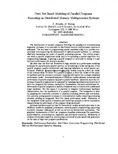
owgraph of the corresponding process. It is important to distinguish determinism of protocol machines in communication nodes from their non-deterministic selection by incoming tokens. The former is related to assuring observable representations of path being selected for tests, while the latter is associated with proper execution of selected paths. By providing external control of each state of each protocol machine in any communication node of interest one can assure reproducible processing of incoming tokens. States of protocol machines determine in fact speci c points in component programs, where breakpoint traps must be installed before program execution. Consider again Figure 10 presenting schematically an example multi- owgraph in a draft form. According to our previous interpretation, the execution of processes P 1, ..., Pk, Pk+1 , ..., Pn , Pn+1 , ... may be viewed as progressing of tokens. Let us assume that a speci c fragment of the corresponding system is to be tested. In Figure 10 a fragment of an example multi- owgraph is framed; it involves three processes Pk, Pk+1 , and Pn . Observe, that processes Pk and Pk+1 may be engaged in some communication, when their tokens go through a communication node. Upon leaving that node, a control ow token of process Pk+1 may be later involved in creating an additional process. The newly created process may later communicate with Pk+1 and Pn , when their tokens arrive at another communication node. There are processes that are not directly involved in communication within the area framed in Figure 10, but they may implicitly a�ect processes Pk , Pk+1 , and Pn from outside the framed area. For example, process P 1 may communicate with Pk and Pk+1 before the latter two enter this area. In order to enable analysis and testing of selected fragments of parallel systems represented by multi- owgraphs we introduce the notion of a test window , being a framed area that contains some interconnected multi- owgraph nodes. The idea of such a window is based on the standard notion of a breakpoint trap used by traditional debuggers. Processes of interest are expected to reach the window top and stop. A tester may then inspect or modify variables of stopped processes, order their step by step execution towards the bottom of a window, or replay their execution after they have reached the bottom. 11
P
1
...
Pk
P
k+1
Pn
...
...
...
P
n+1 ...
...
Figure 10: A test window When control ow tokens of selected processes are inside a window, various structural testing techniques based on the owgraph program model may be applied, e.g., testing paths of individual processes, testing sequences of selected communication nodes, data ow testing, etc. Window framing cannot be arbitrary and it's height and width must be carefully determined for each area of interest, based on the analysis of a related multi- owgraph. The top and bottom window segments constitute in fact vectors of breakpoints, installed at speci c points of relevant processes. Each process of interest must enter a test window at the top. This implies that for each path of the relevant process that leads to any node within that window a breakpoint trap must be set. All other paths of the process that are not involving any nodes from the window do not need any breakpoint and are allowed to bypass it. Similarly, each relevant process must leave at the window bottom, so each related path must also have a breakpoint trap in place. Since processes inside a window may potentially want to interact with other processes from outside that window, the requirement of having breakpoints at the window top and bottom on all entering paths guarantees observability, as no process can enter a test window unnoticed. The window width is also crucial for the correct test preparation, since any communication node that may be visited by a control ow token from inside a window must be entirely contained within that window, i.e., such a node cannot be visited by another token from outside that window. This requirement is necessary to eliminate a "probe e�ect" inside a test window, i.e., any attempt to observe the behavior of processes entering a window will not change their normal behavior within the system area corresponding to that window. Global timing for tokens within a window can be solved by providing a tight control on the progression of tokens within communication nodes belonging to that window; timing of tokens at other types of nodes is irrelevant owing the separation and relative independence 12
of all non-communication nodes. Tight control within a communication node means the total control on all states of all protocol machines, i.e., all tokens within a window must rst arrive to their nearest communication nodes, before they are allowed by the test kernel to proceed to their respective successor communication nodes. This control can be e�ectively implemented, since a number of such states is realistically low, as indicated before. In summary, a test window opened on a multi- owgraph according to the framing rules speci ed here enables structural analysis of a parallel program control ow, assures observability of test cases based on this analysis, eliminates a "probe e�ect" from a parallel program fragment under test and provides a convenient framework for visualization of the testing process.
3.3 Managing a testing procedure
Structural representation of a parallel program under test based on multi- owgraphs and test windows provides a framework for de ning various testing scenarios. This involves interactive (and dynamic) selection of test windows being opened on a working system, as well as selecting a testing strategy for a speci c system fragment. Consider Figure 11 specifying a generic testing procedure based on the concepts developed to this end. Selecting a test window implies de ning a test scenario. The window frame determine exactly what processes in a parallel system are to be tested, and what communication events are to take place during the test. Establishing the window top and bottom segments involves static path analysis to identify all paths that can enter the window, thus require setting up breakpoints. This is just one part of de ning environment conditions for the selected window (test scenario). Another part is related to determining conditions that control paths leading to the selected window. This can be done automatically using a technique of symbolic interpretation [7] applicable to the multi owgraph representations. Relevant conditions must be subsequently satis ed by stopping some processes while allowing other to proceed, as well as assigning selected variables with speci c values. These operations require using a traditional debugger. Having a window being opened on some system fragment a user has to decide what particular testing strategy should be used. This decision depends on the class of errors one may expect to detect, the semantics of a selected system fragment, a size of the window and possibly the speci c test data generation tools available to the user. User makes decisions based on the graphical representation of the system fragment under test. The most suitable testing strategy for test windows is in our view path testing applied to individual processes or to sequences of communication nodes within a window. Execution of tests requires setting up of breakpoint traps at speci c points at paths under test, what can be done either automatically by the supporting testing tool, or interactively by the user using a traditional debugger. Test results are stored for evaluation and test coverage assessment. Further testing may involve another strategy applied to the same window, or changing a window size and/or location. In either case a new test scenario has to be de ned.
4. Functional structure of the tool
We propose a systematic method for structural testing based on our model of parallel software. This model involves nodes containing various component program statements, and arcs corresponding to control ow between individual statements of component processes. We build a multi- owgraph from control owgraphs of component programs and their source code. We use 13
start
define environment
scenario
conditions
generate test data by static analysis
GUI debugger
execute tests user check on behaviour
test coverage ?
N
Y N
all scenarios ? Y end
Figure 11: A generic testing procedure
14
the generalized Taylor's algorithm [11] for static concurrency analysis and the modi ed Laski's algorithm [8] for data ow analysis in order to identify matching communication statements constituting particular communication nodes. The functional structure of our Structural TEsting tool for Parallel Systems (STEPS) under development within the SEPP project is shown in Figure 12; we assume a general message passing model of interprocess communication, as used by PVM and TCP/IP [2, 3]. The tool cooperates with it's user by interpreting and executing a set of commands. Results are put to the data base and can be either displayed by special commands or used by other specialized tools, e.g., for interactive debugging, visualization or calculating quality metrics. The tool uses an interactive graphical interface to separate potentially large volumes of information required by the user for deciding on what processes to test, where to open test windows, what paths to select, what test data to use, etc. To support that we allow users to provide their own procedures, use standard debugging tools, visualization graphics and the PVM kernel; they contribute to the library of functions used by our tool, as it can be constantly developed by the user. The main set of tool functional modules contains the following: �
Analyzer, which analyses commands and invokes the appropriate procedures,
�
Tester, which supports test data generation,
�
Manager, which organizes the testing scenario and supports its execution, by installing
�
Debugger, which supports traditional program debugging based on interactive installation
�
Quali er, which estimates selected quality factors of the analyzed program.
breakpoint traps and enabling replays and recovery functions, of breakpoint traps,
Data base collects information necessary for program testing, debugging, and quality assessment. We distinguish pre-de ne static information that cannot change during the tool work, and dynamic information that describes a current state of the performed analysis. The static information in the data base is the following: �
the PVM based program source code for analysis,
�
individual owgraphs of component programs,
�
data- ow graphs of component programs,
�
sets of communication statements identi ed as "matching" and constituting communication events,
�
the initial multi- owgraph G(N,A) ,
�
speci cation of the assumed testing scenario (window frame). 15
interpreter
OK
N
Y data
library of
test kernel
base
functions
test message
error message
Figure 12: The functional blocks of STEPS
Dynamic information involves the following: �
current state of the tool,
�
current state of the program being tested, including a current form of it's multi owgraph,
�
initial parameters for data and results visualization,
�
information log for respective testing, debugging or recovery steps,
�
intermediate quality factors.
The assumed structure of the tool is exible and allows extensions. In particular, the tool is not limited to just one testing method. As indicated before, testing scenarios may involve any structural testing method, either path or data- ow oriented [1]. This is important because the tool is still under development and is intended to cooperate with other parallel software CASE tools being developed within the SEPP project.
5. Basic tool operations
When describing functionality of the STEPS tool we assume having three kinds of objects: a parallel program source code, a user de ned window and the related testing scenario. With these objects in mind we can de ne STEPS functions: �
update, to enable modi cations of the source code program with some standard editor, 16
� �
clear, to erase all information from the data base, make, to produce an executable code from the source code consisting of compilation units
in C,
�
identify events, to nd matching communication statements in a program source code,
�
de ne window, to select the program fragment for tests,
�
display window, to show the fragment of a program on the user's screen,
�
put window conditions, to set up window entry conditions by a user,
�
resolve window conditions, to interpret and evaluate window entry conditions,
�
select communication nodes, to set up tracing of selected communication events,
�
select path, to de ne the path which has to be tested,
�
show current state, to display the status of control ow tokens,
�
replay state, to return to the previous state within the window,
�
replay window, to return to the previously opened windows,
�
qualify, to evaluate program quality,
�
run, to run the program fragment starting from the window top,
�
continue, to run the program from the current state.
There are two modes for running: step-by-step, or continuous until the window bottom is reached or a speci ed condition evaluates to true. All the above operations are executed by the tool upon typing them in or clicking an appropriate menu entry. User commands are represented by keywords identifying the meaning of the related operation. Arguments for user commands depend on the relevant program structure under test, the related testing models being used for the particular scenario, the type of expected errors, and environment parameters. The STEPS tool supports user operations by providing two kinds of analysis: a static analysis, where the relevant multi- owgraph G(N,A) is interpreted to determine test conditions, and a dynamic analysis, where the program code is executed and its behavior evaluated.
6. Conclusions
We have proposed a new testing model capable of: �
simplifying procedures for structural testing of parallel programs, 17
�
enabling systematic testing based on well de ned classes of errors, and
�
allowing for the use of various testing strategies based on the notion of control owgraphs.
A testing procedure based on our model, is exible, user-friendly and can be adopted to any parallel programming environment that support modularization and at least logical separation of cooperating processes. A structure of a testing tool based on this generic procedure is straightforward and can use existing tools and standard techniques developed for sequential programs. The tool based on the PVM application platform is currently under development [13].
References [1] Beizer, B.: Software system testing. Van Nostrand Reinhold Company, 1990. [2] Comer, D.: Internetworking with TCP/IP Vol.1: Principles, Protocols, and Architecture, 2nd ed., Prentice-Hall, New Jersey, 1991. [3] Geist, A., et al.: PVM 3 users's guide and reference manual. Oak Ridge National Lab, Oak Ridge, Tennessee, 1994. [4] Hecht, M.S.: Flow Analysis of Computer Programs. North-Holland, 1977. [5] Howden, W.E.: Reliability of the path analysis testing strategy. IEEE Trans. Software Eng. SE-2, 208-215 (1976) [6] Korel, B., Laski, J.: STAD - a system for testing and debugging: user perspective. Proc. 2nd Workshop on Software Testing, Veri cation, and Analysis, 19-21 July, Ban�, Canada, 13-20 (1988). [7] Khanna, S.: Logic programming for software veri cation and testing. Comp. J. 34, 350-357 (1991) [8] Laski, J.: An algorithm for the derivation of code nitions in computer programs. Information Processing Letters 23, 85-90 (1986) [9] McDowell, C.F., Helmbold, D.P.: Debugging concurrent programs. ACM Comp. Surv. 21, 593-622 (1989) [10] Richardson, D.J., Clarke, L.A.: Partition analysis: a method combining testing and veri cation. IEEE Trans. Software Eng. SE-11, 1477-1490 (1985) [11] Taylor, R.N.: A general purpose algorithm for analyzing concurrent programs. Comm. ACM 26, 362-376 (1983). [12] White, L.J., Wiszniewski, B.: Testing of computer programs with loops using a tool for simple loop patterns. Software-Practice and Experience 21, 1075-1102 (1991) 18
[13] Winter, S., Kacsuk, P.: Software engineering for parallel processing. Proc. 8th Symp. on Microcomputer and Microprocessor Applications, 12-14 October, Budapest, Hungary, 285-293 (1994).
19