SYSTEMC-AMS MODEL OF A DYNAMIC LARGE-SCALE SATELLITE-BASED AIS-LIKE NETWORK Mu Zhou and Ren´e van Leuken Delft University of Technology, Dept. of Elec. Eng., Mekelweg 4, 2628 CD Delft, The Netherlands. Email:
[email protected];
[email protected]. ABSTRACT In an automatic identification system (AIS), ground base stations can only provide services within a very limited range off the coast. Recent analyses show that low earth orbit (LEO) satellites can expand the service of AIS to a global range. Multi-antenna satellite receivers are suggested to be used to cancel the interference between messages in heavily trafficked areas. In this paper, we present a SystemC-AMS model for a dynamic large-scale satellite-based AIS-like network as the test environment for such algorithms. Complex data type is used in the signal flow. Many effects such as Doppler shifts, path loss, arrival angles, and the real-time transmission and collisions of messages are modeled. This model is further tested with a multi-user detection algorithm in the satellite receiver and validated with receivers in matlab. Index Terms— SystemC-AMS, automatic identification system, multi-antenna satellite receiver, Doppler shift. 1
I NTRODUCTION
The automatic identification system (AIS) [1] was developed to facilitate the efficient exchange of navigational data between ships and between ships and shore stations. The current AIS system uses time division multiple access (TDMA) techniques in the VHF maritime mobile band. Recently, a need has evolved for the capability to detect and track ships at distances from coastlines that are larger than can be accomplished by normal terrestrial VHF communications. Requirements inherent in these long-range applications such as better handing of hazardous cargo, improved security and countering illegal operations require detecting ships at very large distances from shores. Recent analyses [2], [3], [4], [5] show that low earth orbit (LEO) satellites can expand the service of AIS to a global range but the service is only reliable in sparsely trafficked areas. The additional technical challenges LEO satellites faces are collisions of messages in the same time slot from different self-organized time-division multiple access (SOTDMA) cells, collisions of messages between adjacent time slots caused by longer relative propagation channel delay, and relative high variance of path loss and high carrier Doppler. New receiver algorithms are requested to mitigate collisions of messages in the uplink. To develop new algorithms, it requires a test environment for those algorithms. However, the heavy load for the real-time simulation of the simultaneous transmission between tens of thousands of ships and the needs for flexible reconfiguration and extension make the implementation of this kind system difficult under matlab. With the help of SystemC-AMS [6], we can easily model mixed-signal systems more efficiently by using C++ language This work was supported in part by the project BDREAMS at Delft University of Technology in Netherlands, and China Scholarship Council from P.R.China.
only [7, 8, 9, 10, 11, 12, 13, 14]. In this paper, we implement a SystemC-AMS model for a dynamic large-scale satellite-based AISlike network including transmitters, receivers and the channel. Many effects such as Doppler shifts, path loss, arrival angles, and the realtime transmission and collisions of messages are modeled. The remainder of this paper is organized as follows. Section 2 introduces the mathematical model. Section 3 presents the structure of the SystemC-AMS model. Section 4 shows the simulation setup and results. Section 5 concludes this paper. 2
M ATHEMATICAL M ODEL
In this section, we introduce the mathematical model of the system. 2.1
S CENARIO
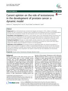
Consider a single satellite in the low earth orbit at altitude ℎ𝑠 (see Fig. 1). In Fig. 1, the view is taken on the observed plane defined by the observed ship, the satellite and the nadir. The red dotted line denotes the satellite orbit which is in another plane intersecting the observed one. The satellite coordinate system is set to a right-handed system: 1. X-axis parallel to the satellite velocity vector. 2. Y-axis parallel to the satellite field of view (FoV) and orthogonal to the satellite velocity vector. 3. Z-axis pointed to the nadir. Ships in the FoV (has radius 𝑟𝐹 𝑜𝑉 ) send out message packets to the satellite frequently to report their navigational information. The 𝑖th ship has its own azimuth seen from the satellite 𝜙𝑖 and ground range away from the nadir 𝑟𝑖 (see Fig. 2), which determines its own parameters related to the effects modeled. One of the typical effects in the AIS-like system is the different carrier Doppler shifts for ships inside FoV. The ship Doppler shift Δ𝑓𝑖 (𝜙𝑖 , 𝑟𝑖 ) is defined by Δ𝑓𝑖 (𝜙𝑖 , 𝑟𝑖 ) =
𝑣𝑟 , 𝜆
(1)
where 𝑣𝑟 is the relative velocity between the observed ship and the satellite, and 𝜆 is the carrier wavelength given by 𝜆=
𝑐 , 𝑓
(2)
where 𝑐 is the speed of light, 𝑓 is the carrier frequency. Then the ship carrier frequency seen from the satellite is given by 𝑓𝑖 (𝜙𝑖 , 𝑟𝑖 ) = 𝑓 + Δ𝑓𝑖 (𝜙𝑖 , 𝑟𝑖 ).
(3)
The ship Doppler phase shift seen at the satellite receiver 𝜑𝑖 is given by 𝜑𝑖 (𝜙𝑖 , 𝑟𝑖 ) = 𝑒𝑗2𝜋Δ𝑓𝑖 (𝜙𝑖 ,𝑟𝑖 )𝑇𝑠 , (4) where 𝑇𝑠 = 1/𝑓𝑠 is the sampling period for the satellite receiver and 𝑓𝑠 is the corresponding sampling frequency. For a satellite at
x
vr
2.2
Satellite
y
Ship
ru
In this paper, a baseband channel model is constructed. The effects of the RF parts of transmitters and receivers are integrated into the baseband channel model because the large amount of samples of the carrier makes the simulation load unacceptable. We model the multiple-input and multiple-output (MIMO) channel at a high level where interference, path loss, arrival angles and Doppler effects are added to the transmitted signals. The channel delay is not explicitly modeled and absorbed into the starting time of ship transmission. QPSK modulation instead of GMSK modulation currently used in AIS system is selected. In the ship transmitter, source signals √ are mapped into a alphabet 22 {1 + 𝑗, −1 + 𝑗, −1 − 𝑗, 1 − 𝑗}. Assume 𝑝 ground ships and 𝑚 satellite antennas with spacing Δ wavelengths. For finite 𝑛 observations, the baseband channel model is defined as X = AB (F ⊙ S) + N, (6)
z hs Nadir
rFoV Earth
Earth center Satellite’s orbit
vs
Fig. 1. The satellite orbit and the geometric relation between the satellite and the observed ship.
Ship
Ship
Iu ru
(I1 , r1 )
B = 𝑑𝑖𝑎𝑔 {𝑏1 , 𝑏2 , ⋅ ⋅ ⋅ , 𝑏𝑝 } ,
where 𝑏𝑖 = 10(𝑃𝑖 +𝐺𝐴𝐺𝐶 )/10 and 𝑃𝑖 = 𝑃𝑖 (𝑟𝑖 ). F is the Doppler phase shift matrix given by ⎡ ⎤ 1 𝜑11 ⋅ ⋅ ⋅ 𝜑𝑛−1 1 𝑛−1 1 ⎢ 1 𝜑2 ⋅ ⋅ ⋅ 𝜑2 ⎥ ⎢ ⎥ (9) F = ⎢. . . .. ⎥ , .. ⎣ .. .. . ⎦ 1 𝜑1𝑝 ⋅ ⋅ ⋅ 𝜑𝑛−1 𝑝
Field of view
rFoV
Ship
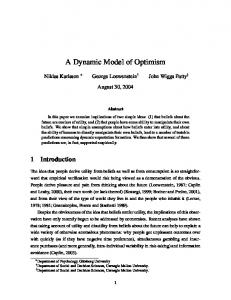
Fig. 2. The top view of the satellite field of view.
altitude ℎ𝑠 = 600km and carrier frequency 𝑓 = 162.025MHz, the maximum ship Doppler shift seen by the satellite is ±3.7kHz. A perpendicular half-wave dipole antenna is used as the ship transmit antenna. The received power is given by 𝑃𝑖 (𝑟𝑖 ) = 𝑃𝑡 (𝑟𝑖 ) + 𝐿(𝑟𝑖 ) + 𝐺𝑎 ,
(8)
√
y
Satellite
(7)
where 𝜑𝑘𝑎 (𝜃𝑖 ) = 𝑒𝑗2𝜋𝑘Δ sin 𝜃𝑖 and 𝜃𝑖 = 𝜃𝑖 (𝜙𝑖 , 𝑟𝑖 ). B is the scaling matrix given by
vs
(I2 , r2 )
where ⊙ is the Schur-Hadamard (pointwise multiplication) operator. X is the received data matrix. A is the steering matrix ⎡ ⎤ 1 1 ⋅⋅⋅ 1 1 𝜑1𝑎 (𝜃2 ) ⋅ ⋅ ⋅ 𝜑1𝑎 (𝜃𝑝 ) ⎥ ⎢ 𝜑𝑎 (𝜃1 ) ⎥, A=⎢ . . .. . ⎣ ⎦ .. .. .. . 𝜑𝑎𝑚−1 (𝜃1 ) 𝜑𝑎𝑚−1 (𝜃2 ) ⋅ ⋅ ⋅ 𝜑𝑎𝑚−1 (𝜃𝑝 )
x
(I3 , r3 )
BASEBAND C HANNEL M ODEL
where 𝜑𝑖 = 𝜑𝑖 (𝜙𝑖 , 𝑟𝑖 ). S is the source matrix given by ⎤ ⎡ 𝑠11 𝑠12 ⋅ ⋅ ⋅ 𝑠1𝑛 𝑠 𝑠 ⋅ ⋅ ⋅ 𝑠 2𝑛 ⎥ ⎢ 21 22 S=⎢ .. . . . ⎥, ⎣ .. . .. ⎦ . . 𝑠𝑝1 𝑠𝑝2 ⋅ ⋅ ⋅ 𝑠𝑝𝑛
where 𝑠𝑖𝑗 denotes the 𝑗-th transmitted symbol of the 𝑖-th ship, and N is a 𝑚 × 𝑛 noise matrix constructed by i.i.d. Gaussian random variables. 3
(5)
where 𝑃𝑡 (𝑟𝑖 ) is the ship transmit power, 𝐿(𝑟𝑖 ) is the path loss, 𝐺𝑎 is the satellite antenna gain. The received power is virtually gained by a value 𝐺𝐴𝐺𝐶 in the satellite receiver to bring the value close to numerical “1.0”. Since the online computation of the received power is not acceptable due to its heavy load, we use a look-up table precomputed from the matlab routine provided by [2] instead, where the index is 𝑟𝑖 and the resolution of the index is 1 nautical mile. Assume the satellite is equipped with a uniform linear array positioned parallel to FoV. The arrival angle of the incident wave from ships on the satellite antenna array is 𝜃𝑖 (𝜙𝑖 , 𝑟𝑖 ). We ignore the detailed formula for 𝜃𝑖 (𝜙𝑖 , 𝑟𝑖 ) here.
(10)
C++ M ODEL
Based on the mathematical basis in section II, a C++ system model is established in this section. The system is divided into four main parts (see Fig. 3), a virtual transmitter, a satellite receiver, a channel and a system controller. In Fig. 3, the solid flow line denotes the signal flow and the dash flow line denotes the control flow. 3.1
C ONFIGURATION DATA
A general C++ class syspara is defined to help manage the entire system (See Listing 1). It stores parameters and the status of the system, and provides functions to update it. The instance of this class is declared globally and initialized in the beginning of the main function of SystemC. The lookup table is put into a file and read into the system when syspara is initialized.
Listing 2. The user b class.
System controller 1 2
Ship_1
3 4
Ship_2
Test algorithm
Channel
5 6 7
Ship_p Satellite Receiver
Virtual transmitter
8 9 10
Fig. 3. The schematic diagram of the C++ system model.
11 12 13 14
Listing 1. The syspara class. 1 2 3 4 5 6 7 8 9 10 11 12 13 14 15 16 17 18 19 20 21 22 23 24 25 26 27 28 29 30 31 32 33
class syspara { public : / / System s i z e i n t m num user , m num trans , m num rec ; double m oversampling , m antenspacing ; / / System time double m global time , m global time l ; / / Ship config . data double ∗p Cafreq u , ∗p lamda u ; double ∗p Pathloss u , ∗p ar angle u ; ... / / S a t e l l i t e config . data double m hight sat , m velo sat ; double m T sat , m earth r ; ... / / Path loss double ∗p Pr ; ... syspara ( ) ; ˜ syspara ( ) ; void i n i t p a r a ( ) ; double doppler sat ( double r u , double phi u ) ; void i n i t P a t h l o s s ( ) ; void genuserdata ( ) ; void gen randpos u ( i n t o) ; void update pos u ( double delta T , i n t o) ; void update spatialpara u ( double delta T , i n t o) ; void checktrans u ( i n t o) ; void shutdowntrans u ( i n t o) ; }; / / Global declaration extern syspara ∗g syspara ;
15 16 17 18 19 20 21 22 23 24 25 26 27 28 29 30 31 32 33 34 35 36 37 38 39 40
Listing 3. The multi users trans b class.
1 2 3 4 5 6
3.2
V IRTUAL T RANSMITTER
The virtual transmitter (See Listing 3) is modeled as a SystemC module which consists of 𝑝 single ship transmitters (See Listing 2). Fig. 4 shows the structure of a single ship transmitter. Inside a ship transmitter, a message encoder produces binary signals, which is then separated into two parallel I/Q paths (See S2P in Fig. 4) fed into a QPSK modulator. The output of the QPSK modulator is modulated signals of a predefined complex data type, st complex (See Listing 4). Because SystemC-AMS does not support tracing a selfdefined data type, we implement the output stream function “p packlen u [o ] ) { ... s sourcesig . write ( packet [ ( i n t ) s cnt . read ( ) ] ) ; }else { . . . } } } void seq proc user b ( ) ; SC HAS PROCESS( user b ) ; s2p QPSK b ∗p QPSK; e x p l i c i t user b ( : : sc core : : sc module name , i n t o in=0) : k( s qrt (2.0) / 2 . 0 ) , o( o in ) { p QPSK = new s2p QPSK b( ”QPSK mod” , k) ; p QPSK−>i c l k ( i c l k ) ; p QPSK−>i r e s e t ( s r e s e t ) ; p QPSK−>i s i g ( s sourcesig ) ; p QPSK−>o QPSK( o QPSK trans ) ; SCMETHOD( comb proc user b ) ; sensitivei s i g ( i s i g [ i ] ) ; p rec [ i]−>o sig ( o sig [ i ] ) ; } } ˜ multi antennas fe b ( ) ; };
Listing 8. The refresh sys class. 1
3 4 5 6 7 8 9 10 11 12
13
14 15 16 17 18 19
20 21 22 23 24 25 26 27 28
Listing 7. The detection class.
1 2 3 4 5
template SCMODULE( detection ) { sc in i c l k ; sc in i r e s e t ;
S YSTEM C ONTROLLER
The system controller is the key part in the model to make the system dynamic (see Fig. 7). The system controller is modeled as a SystemC module consisting of two internal processes regularly refreshing the system status (See Listing 8), where one process refreshes the ship position (𝜙𝑖 , 𝑟𝑖 ) and related data while the satellite is flying over them, and the other process checks the ship transmission time 𝑇𝑢 and triggers the real-time transmission of ships.
2
Listing 6. The multi antennas fe b class.
sc in i s i g [NUMTRECS] ; sc out o d ; / / Internal counter sc signal s cnt , s cnt in ; / / Data matrix for the detection algorithm queue ∗winquere , ∗winqueim ; double ∗∗Qre , ∗∗Qim, ∗∗Rre , ∗∗Rim; ... void comb proc detection ( ){ / / Control counters} void seq proc detection ( ) { / / Ignore the processing o d . write (d) ; } SC CTOR( detection ) { / / Ignore i n i t i a l i z a t i o n data SCMETHOD( comb proc detection ) ; sensitivechecktrans u ( i ) ; } g syspara−>m global time l = g syspara−> m global time ; } } / / The second refreshing process void seq proc refresh sys2 ( ) { i n t count = 0; i f ( i clk2 . read ( ) == 1) { int i ; g syspara−>m global time = sc time stamp ( ) . to seconds ( ) ; for ( i = 0; i < g syspara−>m num user ; i ++) { / / Check ship transmission time g syspara−>checktrans u ( i ) ; / / Count the number of active ships
To channel
System config. data
1. The first refreshing process
10 s
To satellite receiver
Refresh system Two processes
Modules
From/to ship transmitter
2. The second refreshing process and transmitter
1/9600 s
1/(4800P) s
3. Receiver
1/(9600P) s
4. Channel
Time
System controller
Fig. 8. The updating time period of each module. Fig. 7. The schematic diagram of the system controller module. Initialize 34 35 36 37 38 39 40 41 42 43 44 45 46 47 48 49
i f ( g syspara−>p status u [ i ] == 1) { count++; } } } o num sigs . write ( count ) ; } SC CTOR( refresh sys ) { SCMETHOD( seq proc refresh sys1 ) ; sensitive pos