REM2005 June 30th – July 1st 2005 FRANCE
Tactile Interfaces: Technologies, Applications and Challenges M. Hafez and M. Benali Khoudja CEA LIST 18 route du panorama, 92265 Fontenay aux Roses, France Phone: +33-1 46 54 97 31, Fax: +33-1 46 54 75 80, E-mail:
[email protected],
[email protected]
Abstract - Tactile interfaces are used to communicate information through the sense of touch, which is an area of growing interests from the research community. Potential applications include virtual training for surgeons, remotely touching materials via internet, automotive industry, active interfaces for blind persons, and sensory substitution devices.
I. INTRODUCTION The sense of touch is quite rich and includes beside the cutaneous sensitivity, the sensitivity to an applied pressure, vibration and a variation in the temperature [Caldwell et Gosney 1993]. Different research groups have developed laboratory prototypes to study and understand the sense of touch. However, the designs and the actuator technologies used cannot satisfy mass production, as the assembling of different parts becomes time-consuming and practically impossible at the scale of these micro actuators which have a size in the millimeter range. Tactile stimulation can be accomplished in different ways. The technologies for virtual environment systems were inspired from dot matrix printers technologies and Braille systems for blind people. Solutions based on mechanical needles actuated by electromagnetic technologies (solenoids, voice coils) [Wagner et al. 2002] and [Fukuda et al. 1997], piezoelectric crystals [Pasquero and Hayward 2003], Shape Memory Alloys (SMA) [Taylor et al. 1998], pneumatic systems, and heat pump systems based on Peltier modules have been proposed. Other technologies such as electrorheological fluids, which cause an apparent change in the viscosity under the application of an electric field, are under investigations [Kenaley and cutkosky 1989]. Technologies dedicated to medical applications such as electro-tactile and neuromuscular stimulators have not yet been used because of their invasive nature. A comprehensive state of the art survey on tactile displays can be found in [Benali Khoudja et al. 2004 I].
developed based on micro linear electromagnetic actuators (VITAL interface [Benali Khoudja et al. 2004 II].) and piezoelectric ceramics [Vujic et al. 2004].. These interfaces have a limited number of actuators (typically a matrix shape with 8x8 or 10 x 10 actuators). They are also called “dynamic interfaces”. A finger (or few fingers) rests on the display whose content is continuously refreshed. However, the information transmitted to the skin is limited compared to a static display that is explored by the hand (applications for blind persons). In fact, dynamic interfaces do not reproduce the friction forces generated when a finger explores a relief , which is an important source of information for the visually impaired. In order to satisfy these requirements for blind applications, quasi static interfaces have been developed [Hafez et al. 2004] and will be covered in a dedicated section of this paper. Finally, a thermal interface is presented. The heat transfer occurring between the fingertip and different explored surface materials is simulated and reproduced on the thermal interface. A comparison between a thermal model and some experimental results are also presented in this paper. II. VIBROTACTILE INTERFACES A. VITAL based on electromagnetic micro actuators The design approach used to build the new vibrotactile interface is based on a multi-layer approach where the complexity of the assembling process is independent from the number of micro-actuators. The multi layer concept is based on linear electromagnetic actuators with microcoils.
This paper gives an overview of different tactile interfaces that have been developed at CEA LIST in order to communicate different types of information through the sense of touch. Vibrotactile stimulators have been
page
REM2005 June 30th – July 1st 2005 FRANCE
Fig. 1 VITAL - 8x8 vibrotactile display based on electromagnetic actuators These micro-coils can be either machined on a single piece of copper (monolithic structure), or manufactured on a multi-layer printed circuit. The first prototype is a 8×8 tactile display based on conventional solenoids (see Fig. 1). Pin spacing in the first prototype was 5 mm with a pin diameter of 2 mm. NdFeB permanent magnets of 2 mm diameter and 4 mm height are fixed on a flexible magnetic membrane. The flexible membrane is laser cut in the same monolithic steel sheet and positioned on the top of the coils. The flexible membrane is acting as a guiding mechanism for the magnets. The display has a maximum pin deflection of ±100µm. It can accurately operate at frequencies up to 800Hz, with a first resonance frequency at 270Hz. The maximum static force delivered by each micro-actuator is about 13mN. The maximum power dissipated in each coil for R = 1.6 Ω and I = 0.5 A is P = 400mW. In real work conditions the current is about 0.2A which corresponds to a power dissipated of about 64mW. The second generation of the VITAL display is a 8×8 vibrotactile display based on a fabrication process that integrates the coils on a multi-layer PCB (see fig. 2). With this technology the number of turns ‘N’ is increased as the number of layers of the PCB is increased. It is also a widely used process in electronics industry and cost would be quite competitive when mass produced. Each coil is 2 mm external diameter with 1.6mm thickness. In this case the range of the allowed current is between 0 and 1A. The maximum power dissipated in each coil for R = 0.4 Ω and I = 0.8A is P = 256mW.
constant for a given actuator configuration, therefore in order to control the force and the indentation amplitude delivered by each micro actuator, the current in each coil is controlled. In our case, the nominal current in each coil is a bi-directional [0,1]A. Due to the large number of micro actuators forming the tactile matrix, a dedicated electronic architecture has been developed and realized. The first step was to design a compact amplifier to drive such values of current and to build the appropriate architecture to embed them in a size limited power board. A control board based on a DSP (Digital Signal Processor) to address and calculate the wave form of the signal applied to each coil was also built. This DSP board is also connected to the graphical user interface by a USB or a RS232 link. The general diagram of the electronic hardware architecture is presented in fig. 3.
Fig 3. General diagram of the electrical hardware
B. Vibrotactile interface with PZT combs When the tactile application is to reproduce textures, which requires a high density and small interspaces between the different actuators (1 mm which corresponds to the mechanical resolution for the human being), other actuation technologies are explored. The limitation of the previous technology is the strong interaction between the different magnets that would limit further integration. Therefore, another solution based on piezoelectric ceramics is proposed here (see Fig. 4).
Fig 2. VITAL interface with a multi layer approach The electronic system that is used to drive a matrix tactile interface composed of several micro actuators is presented in this section. The amplitude of the indentation and the force delivered by each micro actuator is directly proportional to the product N×I. It is obvious that N is
page
REM2005 June 30th – July 1st 2005 FRANCE
Fig. 4. Piezoelectric vibro tactile interface concept
Fig. 6: Multilayer comb structure with the PCB
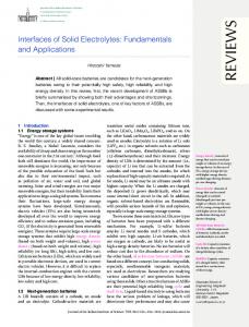
A concept of a compact, robust and low-cost piezoelectric based vibrating tactile interface is described. This tactile interface is composed of 10 identical multilayer bimorph active structures with a comb shape. Each comb is composed of 10 thin teeth bimorph piezoelectric actuators. The tactile interface has one hundred (10 x 10) independent actuators in contact with the fingertip, each having a bandwidth in the range of 1 kHz. Each tooth of the comb structure is an independent bending actuator. However, in order to increase the rigidity and robustness of these bending teeth, the comb was composed of three thin layers: PZT –metallic substrate-PZT (see Fig 5).
The first comb structures were fabricated using conventional methods. A bulk ceramic PZT sheet PIC 151 from PI Ceramic, 200 microns thick, was coated on both sides of a 100 microns thick stainless steel sheet. Electro conductive epoxy glue was used in order to ensure superior electrical contact with the PZT sheets. The obtained multilayer (PZT – epoxy – stainless steel – epoxy – PZT) is then machined to obtain comb structures. First samples of combs were obtained using pulsed fundamental mode Nd-YAG slab laser micro-cutting machine. Laser cutting machines can accurately produce complex contours with a small path size of the beam (typically 0.05 mm). As laser machining cut by melting the material in the beam path, it was interesting to verify if the cutting process would preserve the polarization of the ceramics. The obtained samples and their dimensions in mm are shown in Fig 7. In order to easily evaluate and test this cutting technique, the comb structures were not made to scale for the tactile interface application.
Fig. 5. Multilayer structure of the comb structure Depending on the fabrication process, the two layers of PZT are either coated with electro-conductive glue to the metallic substrate or deposited through a sol-gel coating process. The advantage of using this design is the screen printing or sputtering deposition of the electrical paths and connections on each side of the base of the comb. The electrical tracks are connecting the electrodes of each bender to a surface mounted component (SMC) connector (see Fig 6). Two flat cables were used to connect each side of the comb actuator to the power circuit board.
Fig. 7. Two comb structures machined with laser cutting III. QUASI-STATIC INTERFACES Blind persons rely on the sense of touch and is a main channel of information. Braille interface exists however they are extremely expensive (about 15 k€) and are restricted to Braille reader. Therefore, there is a need to develop large surfaces that can display also graphical information. We proposed a new concept for a tactile interface with a large surface (up to A4 format) with a high density of Shape Memory Alloy micro actuators.
page
REM2005 June 30th – July 1st 2005 FRANCE
The system is composed of a single piece “monolithic” SMA sheet that has been cut using laser technology or wire Electro Discharge Machining (wire EDM) to generate a high density matrix of taxels that can be addressed independently. The concept allows a significant simplification of the assembling process. An interspace of 1.25 mm between each taxel is satisfied, which corresponds to a human being’s mechanical resolution. This interspace would allow the blind person to explore continuous relieves using the two hands. When the interspace is doubled (one actuator on and the other off) this corresponds to a Braille interspace (2.5 mm). Therefore, the system introduced allows the display of both high resolution graphics and Braille characters.
total of 4 peltier elements, one along each side of the vibrotactile interface are used) that could be integrated in the vibrotactile interface so that it would generate simultaneously a thermal and a vibrotactile stimulation.
Fig. 9. Tactile interface with both vibrotactile and thermal stimulation.
Novel Approach Tactile interfaces developed thus far based SMA-based relied on wire and spring shapes of the SMA actuator. These shapes were chosen because they are commercially available and several models of the thermo-mechanical behavior have been studied and proposed. However for a tactile interface with a large surface area where thousands of actuators are necessary, such shapes are not a good solution. The assembling process is time-consuming and quite difficult at this scale. The concept we propose is a single sheet of SMA with all the actuators integrated (see fig. 8). The SMA actuators are small cantilever beams that work in a bending mode. Beams would either bend to deform the fingertip which rests on the tactile surface or deform first and reach the austenitic shape (out of plane) before the fingertip applies a force on it when exploring the tactile information.
The heat transfer occurring between the fingertip and an explored surface plays a major role in the tactile exploration. Therefore, it is of prime importance to understand and model this thermal transfer to be able to regenerate it on the tactile interface. This model involves conductive and convective exchanges. The conduction is due to the contact of the skin with the material, whereas the convection is due to the blood circulation in the body which acts as a thermo regulator to the air surrounding the finger and the explored sample (see fig. 10).
Fig. 10. A schematic representation of the heat transfer process occurring in the contact area. Thermal model – Electrical analogy Fig. 8. Monolithic SMA based tactile interface IV. THERMAL INTERFACES Virtual reality is one of the potential applications for tactile interfaces. In order to reproduce different textures and to distinguish between different materials such as wood and glass for instance, thermal feedback, when added to vibrotactile stimulation, would introduce a new dimension of realism. Figure 9 shows 2 peltier modules (a
When we apply a temperature difference between two points in a conductive medium, it creates a temperature flux between these two points. This is equivalent to a potential difference applied at the two ends of a resistor. Moreover, by applying this temperature difference, the flux increases the temperature of the cold point trying to reach an equilibrium state after a certain period of time. This time is equivalent to the loading time of a capacitor. This means that we can make an analogy between the
page
REM2005 June 30th – July 1st 2005 FRANCE
thermal heat transfer occurring in the contact area and some electrical circuits. A comprehensive presentation of this thermal model could be found in [Benali Khoudja et al. 2003]. Experimental results In order to measure heat transfer between the finger and different types of materials, an experimental setup composed of different modules is built and shown in figure 11. A radiator of thermal resistance of 0.6°C/W that supports a Peltier module. This cell is a 25x25x3.4 mm3 which reaches a power of 18.1W with a current of 2.1A and a maximum potential difference of 15.4V. Different materials were used during experiments such as glass, copper and Aluminum. The choise of materials is based essentially on their different thermal conductivities (0.88W/m°K; 203W/m°K, and 380W/m°K respectively). The temperature variation as a function of time is presented in figure 12. Each material sheet was maintained at a desired initial temperature (38°C). We have observed the cooling behavior when a finger is positioned on these samples. There is a good similarity between the results obtained by the simulation model and the experimental results.
IV. CHALLENGES Developing an interface that is low cost and with a high density of actuators is a challenge. Another challenge is to develop the fundamentals of a new tactile "language". By getting inspired from hand-written and voice recognition, we developed the first building blocks of this tactile language that is capable of communicating "emotional" and "feelings" information. We define a tactile letter as any static pattern including a combination of active and not active taxels (located on the tactile surface). We can then combine these tactile letters, assemble them into words, and repeat them with different intervals. The chain of stimulations is defined as the "tactile string". Some illustrating examples are presented in figure 13. The strings represent a "divergent wave", a "vertical shutter" and a "horizontal line sweep".
Divergent wave
Vertical shutter
Horizontal line sweep
Fig. 13. Elementary tactile strings Fig. 11. Experimental setup for temperature feedback.
More tactile strings were considered such as: convergent wave, horizontal shutter, vertical line sweep and activated all. Six different tactile words (i.e. tactile stimulation that evocates a specific feeling or meaning) were determined and experiments were carried out in order to validate the emotional representation of these tactile words (do tactile words allow to communicate the feeling for which they were?), and then the degree of tactile words discrimination has been evaluated. It is important to see if the different tactile words are perceived in a different way.
Fig. 12. Simulations-vs-experiments.
The 6 feelings that have been represented so far by a different tactile word are: affection, feeling good (relaxed), stress, pain, urgency (emergency),
page
REM2005 June 30th – July 1st 2005 FRANCE
interrogation (search). Our future work focuses on how to enrich this tactile language. REFERENCES [Caldwell et Gosney 1993] D.G. Caldwell, C. Gosney, "Multi-Modal Tactile Sensing and Feedback (Tele-Taction) for Enhanced TeleManipulator Control", Proceedings of the IEEE/RSJ, Yokohama, Japan, July 26-30, (1993). [Wagner et al. 2002] C.R. Wagner, S.J. Lederman, R.D. Howe, "A Tactile Shape Display Using RC Servomotors", the tenth symposium on haptic interfaces for virtual environment and teleoperator systems, Orlando USA, March (2002). [Fukuda et al. 1997] T. Fukuda, H. Morita, F. Arai, H. Ishihara, H. Matsuura, "Micro Resonator Using Electromagnetic Actuator for Tactile Display", MHS, Nagoya, Japan, (1997). [Taylor et al. 1998] P.M. Taylor, A. Moser, A. Creed, "A Sixty-Four Element Tactile Display Using Shape Memory Alloy Wires", Elsevier Science B.V., pp. 163-168, (1998). [Pasquero and Hayward 2003] J. Pasquero and V. Hayward, "STReSS: A Practical Tactile Display System with One Millimeter Spatial Resolution and 700 Hz Refresh Rate", Eurohaptics, pp. 94-110, Dublin Ireland, (2003).
[Kenaley and cutkosky 1989] G.L. Kenaley, M.R. Cutkosky, "Electrorheological Fluid-Based Robotic Fingers With Tactile Sensing", Proc. IEEE International Conference on Robotics and Automation, Scottsdale AR, pp. 132-136, (1989). [Benali Khoudja et al. 2004 I] Benali Khoudja M., Hafez M., Alexandre JM. et Kheddar A. “Tactile Interfaces: A state of the Art Survey” International Symposium on Robotics (ISR 2004), Paris, France, 24-26 Mars 2004. [Hafez et al. 2004] Hafez M., Khelfaoui F., Nesnas H., et Chaillet N. “Monolithic SMA Large Surface With a High Density of MicroActuators for Tactile Displays” 9th International Conference on New Actuators, ATUATOR 2004, Bremen, Germany, 14-16 Juin 2004. [Vujic et al. 2004] Vujic N., Hafez M., et Boy P. “Thick Film Deposition of Piezoceramics Using Sol Gel Technology, Application to a Tactile Interface” 9th International Conference on New Actuators, ATUATOR 2004, Bremen, Germany, 14-16 Juin 2004. [Benali Khoudja et al. 2004 II] Benali Khoudja M., Hafez M., Alexandre JM. et Kheddar A. “the VITAL interface: A Vibrotactile Interface for Blind Persons” IEEE International Conference on Robotics and Automation (ICRA), New Orleans USA April 26 – May 1, 2004. [Benali Khoudja et al. 2003] Benali Khoudja M., Hafez M., Ben Achour J. et Kheddar A. “Thermal Feedback for Virtual Reality” International Symposium on Micromechatronics and Human Science (MHS 2003) IEEE Conference, Nagoya, Japon. 19-22 Octobre, 2003.
page