5792
IEEE TRANSACTIONS ON ANTENNAS AND PROPAGATION, VOL. 61, NO. 11, NOVEMBER 2013
The RVD with the matching network was implemented and the performances measured. The measured reflection coefficients show that the RVD is matched over the desired frequency band. In addition, the measured target-reflected signals demonstrate that more energy is radiated and more energy concentrated in the main pulse.
Tailoring Radiation Patterns in Broadband With Controllable Aperture Field Using Metamaterials Mei Qing Qi, Wen Xuan Tang, He-Xiu Xu, Hui Feng Ma, and Tie Jun Cui
REFERENCES [1] D. J. Daniels, “Ground Penetrating Radar,” 2nd ed. The Institute of Engineering and Technology—Radar, Sonar, Navigation and Avionics, pp. 187–199, 2004. [2] S. Vitebskiy, L. Carin, M. A. Ressler, and F. H. Le, “Ultra-wideband, short-pulse ground-penetrating radar: Simulation and measurement,” IEEE Trans. Geosci. Remote Sensing, vol. 35, no. 3, pp. 762–772, May 1997. [3] K. Kim and W. R. Scott, “Design of a resistively loaded vee dipole for ultrawide-band ground-penetrating radar applications,” IEEE Trans. Antennas Propag., vol. 53, pp. 2525–2532, Aug. 2005. [4] T. P. Montoya and G. S. Smith, “Land mine detection using a groundpenetrating radar based on resistively loaded vee dipoles,” IEEE Trans. Antennas Propag., vol. 47, pp. 1795–1806, Dec. 1999. [5] W. R. Scott, K. Kim, and G. D. Larson, “Investigation of a combined seismic, radar, and induction sensor for landmine detection,” J. Acoust. Soc. Amer., vol. 115, no. 5, p. 2415, May 2004. [6] J. G. Maloney and G. S. Smith, “A study of transient radiation from the Wu-King resistive monopole—FDTD analysis and experimental measurements,” IEEE Trans. Antennas Propag., vol. 41, no. 5, pp. 668–676, May 1993. [7] D. Caratelli, H. Poley, and A. Yarovoy, “EM characterization of resistively loaded printed dipole antennas for GPR applications,” in Proc. IEEE Int. Conf. Ground Penetrating Radar, Jun. 2010, pp. 1–6. [8] A. S. Petrov and M. V. Kovaleva, “Matching the input impedance of a short monopole to the wave impedance of the feeder with the use of an L-network consisting of finite-Q inductances,” J. Commun. Tech. Elect., vol. 57, no. 4, pp. 381–384, Apr. 2012. [9] D. M. Pozar, Microwave Engineering, 3rd ed. New York, NY, USA: Wiley, 2005, ch. 5. [10] H. J. Carlin, “A new approach to gain-bandwidth problems,” IEEE Trans. Circuits Syst., vol. CAS-24, no. 4, pp. 170–175, Apr. 1977. [11] H. J. Carlin and P. Amstutz, “On optimum broad-band matching,” IEEE Trans. Circuits Syst., vol. 28, no. 5, pp. 401–405, May 1981. [12] B. S. Yarman, M. Sengul, and A. Kilinc, “Design of practical matching networks with lumped elements via modeling,” IEEE Trans. Circuits Syst., vol. 54, no. 8, pp. 1829–1837, Aug. 2007. [13] V. Iyer, S. N. Makarov, D. D. Harty, F. Nekoogar, and R. Ludwig, “A lumped circuit for wideband impedance matching of a non-resonant, short dipole or monopole antenna,” IEEE Trans. Antennas Propag., vol. 58, no. 1, Jan. 2010. [14] T. T. Wu and R. W. P. King, “The cylindrical antenna with nonreflecting resistive loading,” IEEE Trans. Antennas Propag., vol. AP-13, no. 3, pp. 369–373, May 1965. [15] K. Kim and W. R. Scott, “Design and realization of a discretely loaded resistive vee dipole for ground-penetrating radars,” Radio Sci., vol. 39, pp. 1–9, Jul. 2004. [16] R. M. Sharpe, J. B. Grant, N. J. Champagne, W. A. Johnson, R. E. Jorgenson, D. R. Wilton, W. J. Brown, and J. W. Rockway, “EIGER: Electromagnetic interactions generalized,” in Proc. IEEE AP-S Int. Symp. Digest, Quebec, Canada, Jul. 1997, pp. 2366–2369. [17] C. V. M. Barton and K. D. Montagu, “Detection of tree roots and determination of root diameters by ground penetrating radar under optimal conditions,” Oxford J. Tree Phys., vol. 24, no. 12, pp. 1323–1331, Oct. 2004. [18] A. Lazaro, D. Girbau, and R. Villarino, “Simulated and experimental investigation of microwave imaging using UWB,” Progr. Electromag. Res., vol. 94, pp. 263–280, 2009. [19] M. M. Weiner, Monopole Antennas. New York, NY, USA: Marcel Dekker, 2003, pp. 107–118. [20] Agilent Overview: Advanced Design System (ADS) [Online]. Available: http://www.home.agilent.com 2000 [21] K. Kim and W. R. Scott, “Numerical analysis of the impulse-radiating antenna,” Sensor Sim. Notes, no. 474, pp. 1–34, Jun. 2003. [22] M. Ghavami, L. B. Michael, and R. Kohno, Ultra Wideband: Signals and Systems in Communication Engineering, 2nd ed. Chichester, U.K.: Wiley, 2004, ch. 1, 2.
Abstract—Metamaterials (MTMs) have advantages to control electromagnetic (EM) waves with high flexibility. However, the application of MTMs in antennas has mainly focused on controlling the phases of EM waves (e.g., to transform spherical waves into planar waves in flat lens and Luneburg lens). In this work, we experimentally demonstrate a method to control the radiation patterns in broadband using MTMs. By controlling the inhomogeneous refractive-index distribution of MTMs, both amplitudes and phases of EM waves on the antenna aperture are designed as required. We present an example to produce a new MTM lens antenna to possess high gain and low sidelobes simultaneously. Experimental results show excellent performance of the antenna in a broad band from 12 GHz to 18 GHz. Index Terms—Broadband, gradient index, high gain, lens antennas, low sidelobes, metamaterials, radiation patterns.
I. INTRODUCTION The radiation pattern is one of the most important parameters of antennas, which have been widely used in modern science and technology. Different applications have different specific requirements to the radiation patterns (directivity, gain, beam width of main lobe, sidelobes, and bandwidth). Hence, controlling the radiation patterns is particularly important. In the traditional microwave and optical communities, dielectric lenses have been utilized to improve the directivity in antenna systems. Due to their fundamental property of ‘bending’ the propagation of EM waves, they are used to narrow the beam from a relatively small aperture (e.g., from a horn antenna) and consequently modify the radiation patterns [1]. In a conventional convex lens that made of uniform material such as glass, spherical waves originated from the focal point of the lens are converted into collimated beams. However, there always exist geometry and wave aberrations in a single conventional lens that limit the lens performance. One solution to this problem is to use multiple lenses to overcome most of the optical distortion or aberration. Unavoidably, a multi-lens system usually has a large volume. Another solution is to use some special lenses that are composed of inhomogeneous materials, such as the Luneburg lens [2], in which aberrations are effectively reduced because the EM waves are gradually modified. Because the inhomogeneous Manuscript received March 10, 2013; revised July 05, 2013; accepted July 30, 2013. Date of publication August 07, 2013; date of current version October 28, 2013. This work was supported in part by the National Science Foundation of China under Grant Nos. 60990320, 60990324, 61138001, 61171024, 61171026, and 60921063, in part by the National High Tech (863) Projects under Grant Nos. 2011AA010202 and 2012AA030402, and in part by the 111 Project under Grant No. 111-2-05. M. Q. Qi is with the State Key Laboratory of Millimeter Waves, Southeast University, Nanjing 210096, China and also with the East China Research Institute of Electronic Engineering, Hefei 210088, China. W. X. Tang, H. F. Ma, and T. J. Cui are with the State Key Laboratory of Millimeter Waves, Southeast University, Nanjing 210096, China (e-mail:
[email protected]). H.-X. Xu is with the Missile Institute, Air Force Engineering University, Xi’an 710051, China. Color versions of one or more of the figures in this communication are available online at http://ieeexplore.ieee.org. Digital Object Identifier 10.1109/TAP.2013.2276921
0018-926X © 2013 IEEE
IEEE TRANSACTIONS ON ANTENNAS AND PROPAGATION, VOL. 61, NO. 11, NOVEMBER 2013
lenses require continuously changed index of refraction, metamaterials (MTMs) have been considered as one of the best constructions, as reported recently in [3] and [4]. MTMs are artificial materials that are composed of periodic or non-periodic EM resonator arrays. Due to their great potentials to control EM waves [5], a lot of devices have been proposed, such as the invisibility cloaks [6]–[12], optical and microwave illusions [13], [14], EM concentrators and rotators [15]–[18], and optical and microwave black holes [19], [20]. Among the many applications, MTMs have been properly implemented to make new antennas or improve antennas performance. For example, some kinds of MTM lenses have been proposed, such as the zero-refractive index lenses [21] and the negative-refractive index lenses [22]. However, such lenses are made of resonant structures and hence can only work in a narrow frequency band. The gradient refractive-index (GRIN) lens [23] is a specific inhomogeneous lens. When located in front of a point source (or an electrically-small antenna in practice), it serves to tailor the phase fronts and consequently helps to gain high directivities. The traditional Luneburg lens, half Maxwell fisheye lens [24], flat-planar lenses [25], [26], and optical- transformation based flatted Luneburg lenses [3], [4] are all belonging to GRIN lenses. The GRIN lenses can be realized by non-resonant MTMs and, therefore, obtain a broad operating bandwidth [3], [4], [24]–[26]. In the above-mentioned GRIN lenses, MTMs have been used to control only the phases so that the spherical waves emitted from the source are transformed into plane waves to reach high gains. However, the radiation patterns cannot be controlled. In a lot of applications, antennas are required to have not only high gains but also other features like very low sidelobes, which have usually been realized by phase-array techniques. In this work, we introduce and experimentally demonstrate a method to control the antenna’s radiation patterns by tailoring the amplitudes and the phases of EM waves simultaneously, so that the amplitudes and the phases of EM fields on the antenna aperture satisfy certain distributions. As an example, we design and fabricate a MTM lens antenna that possesses a special aperture field distribution with nearly uniform phase and tapered amplitude, resulting in highly-directive radiation with extremely low sidelobes. Both simulation and measurement results are presented to demonstrate the performance in a broad band from 12 GHz to 18 GHz.
5793
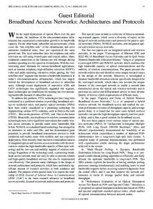
Fig. 1. Sketch of the proposed antenna. (a) Ray tracing in the proposed GRIN MTM lens antenna. (b) The distribution of refractive index in the lens.
Fig. 2. The schematic diagram of the ray tracing.
B. Ray Tracing in the Lens To decide the ray tracing in a GRIN lens, the law of refraction is used for analysis. Fig. 2 shows the deflection of a ray at the interface between different media. represents the refractive index at the point and at the point of . According to the law of of refraction, their relation is written as:
(1) (2) is defined in Fig. 2. The tangent slopes of the ray tracing at adjacent are noted as: two points and
(3) II. DESIGN METHODOLOGY AND OPERATION MECHANISM A. Geometry of a Flat Cylindrical Lens In general, the distribution of refractive index of an arbitrarily-shaped lens determines the amplitude and the phase of aperture field. Hence we can change the refractive index inside the lens to control the aperture field. Without losing generality, we consider a slab cylindrical lens as an example, as shown in Fig. 1(a), whose refractive index is supposed to be cylindrically symmetrical. If it is required to achieve a highly-directive beam in the direction normal to the flat lens, a uniform phase is needed on the flat aperture. Hence the spherical waves excited by a feeding source (replaced with a horn antenna in Fig. 1(a)) must be transformed to plane waves when propagating through the flat cylindrical lens. Ray tracings are presented in Fig. 1(a) to indicate the propagating direction of the wave and to show the spherical-to-plane wave transformation. In this scenario, the equivalent phase center of the feed is located at the origin of the cylindrical coordinate system and the focal length is . The total thickness of the lens is noted as and the aperture diameter is . noted as
Hence,
(4)
So (3) can be re-written as:
(5)
Based on the above analysis, the ray tracing can be approximately to 0.1 discretized with short line segments. In this work, we fix at 15 GHz) to guarantee the substitutability. According mm ( to (3)–(5), once the distribution of the refractive index is determined, the angle can be calculated and the ray tracing in the GRIN lens can be depicted as shown in Fig. 1(a) for example.
5794
IEEE TRANSACTIONS ON ANTENNAS AND PROPAGATION, VOL. 61, NO. 11, NOVEMBER 2013
C. Design of the Impedance Matching Layers In order to reduce the reflection, two impedance matching layers (IMLs) are added to the top and the bottom of the 3D cylindrical lens respectively. According to the theory, the thickness of the IML is one quarter of the wavelength at the operating frequency. In practice, because the IML works in broadband and the wavelength varies in different media, the thickness of the IML is approximately one-quarter of the wavelength at center frequency. In order to reduce the complexity for design and fabrication, permeabilities of the composing MTMs are restricted to be unity and the refractive index distribution for the IML is therefore decided by the square root of the refractive index in the core layer. ) is chosen as In this work, the thickness for each IML (noted as at the center frequency , which two tenth of the wavelength . The refractive index of the core layer and the IML are is close to , respectively. The input impedance on the interface noted as and between the air and the IML is
If we are required to achieve a high-gain lens antenna with low side lobes, the amplitude distribution on the lens aperture will approach and the phase disTaylor circular array distribution noted as tribution is uniform [1]. To implement such aperture distributions, two techniques are proposed. Firstly, a proper feeding horn antenna with identical E- and H-plane radiation patterns is carefully designed since the cylindrical lens is rotationally symmetric [28]. Secondly, a global optimization algorithm, the particle swarm optimization, is adopted to optimize the refractive-index distribution of the lens [29]. Particle swarm optimization is an algorithm that capable of optimizing a non-linear and multidimensional problem, usually reaches good solutions efficiently while requiring minimal parameterization. The main concept is that we have particles of a swarm moving in a problem space and evaluate their positions through a fitness function. Let denote a particle’s position (in the coordinates) and denote the particle’s flight velocity over a solution space. The velocity and the position of a particle are updated by the following stochastic and deterministic updating rules [29] as:
(6) in which the IML. Therefore,
and
(12)
is the propagation phase in
(13) (7)
in which is the operating frequency. Therefore, we can obtain the reflection coefficient at the interface between the lens and the air as:
(8)
is an inertia weight, and are acceleration constants, is a random number between 0 and 1, Pbest is the best previous position of a particle, and Gbest is the index of the best particle among all particles in the swarm. When applied to a certain problem, a fitness function is defined to determine “how good” the current values for the parameters are. We in (9) to guarantee set so that the index of the lens at the edge can approach that of the free space. In our design, we define the particle position as where
D. Refractive Index Distribution in the Lens To express the refractive index distribution in the lens along the radial direction, a 10-order polynomial is adopted as
(14) The fitness function for optimizing the refractive index distribution of the lens is defined as follow:
(9) Obviously, the refractive index distribution in the lens is obtained when the coefficients in the polynomial is determined. According to the law of refraction mentioned above, the wave emitted from the feed in the angle of ( defined in Fig. 1(a)) propagates through the lens into on the aperture provided that the the free space at the point of distribution of the refraction index along the radial direction is given. of the field on the aperture We can obtain the phase distribution ) by calculating the optical path (defined as
(10) The radiation power of the feeding source is noted as , and the . According to power distribution on the lens aperture is noted as the energy conservation law, we can obtain [27]
(11)
(15) are the weights for the amplitude and phase distriin which and bution of the aperture field, respectively. The weights can balance the two aspects. When the value of increases, the amplitude distribution . Therefore, on the aperture has more opportunity to approach we can control the output of optimization through adjusting the value of . To obtain a low side-lobe lens antenna, the aperture of the lens should be much larger than the operating wavelength. Here, we set (at 15 GHz). Besides, the focal length has an important impact on the far-field performance, especially on the side-lobes. If is large , the edge diffraction from the feed will result in with respect to high side-lobes. However, if the value of is too small, the lens will be bulky or the values of the refractive index for the lens will be extremely large. These issues will bring in difficulties for lens realization. Therefore, in our design, the focal length is set to 30 mm. According to the desire that every optical path from the feed to the upper aperture of the lens should have uniform phase delay, the relation
IEEE TRANSACTIONS ON ANTENNAS AND PROPAGATION, VOL. 61, NO. 11, NOVEMBER 2013
5795
Fig. 3. The reflection in the central area on the interface between the lens and . the air with and without the IMLs
Fig. 5. Relations between the refractive index and the dimension of unit cells. (a) The 2 2 2 mm drilled-hole F4B unit cells for the core layer. (b) The 2 2 1 mm drilled-hole F4B unit cell for the IMLs. (c) Frequency response of the refractive index with different values of in unit cells of the core layer. (d) Frequency responses of the refractive index with different values of in unit cells of the IMLs.
Fig. 4. Simulation results of the designed MTM lens. (a) The electric field distribution in the E-plane. (b) The electric field distribution in the H-plane. (c) The amplitude distributions on the lens aperture. (d) The phase distributions on the lens aperture. Fig. 6. The fabricated MTM lens antenna. (a) The sample of the proposed lens antenna. (b) The drilled-hole dielectric. (c) The feed used in the lens antenna.
between the parameters , and by the following equation [26]:
can be preliminarily expressed
(16) We can estimate the thickness of the lens or the maximum refractive according to the above equation. For example, if is fixed index will apto 104 mm and the focal length is chosen to be zero, proach 2. In this case, a substrate with relative permittivity no less than 4 and low loss tangent is needed to cover the refractive index range from 1 to 2 using the drilled-hole MTM unit cells. In our design, we to 1 and to , which is the refractive index of F4B set that is implemented for fabrication. The target of optimization is to obtain an aperture field distribution with Taylor circle array amplitude and uniform phase so as to guardB. Finally, the antee the side-lobes of the lens antenna below optimized refractive-index distribution is in the form of (9) with parameters of , and . Accordingly, , as explained the refractive-index distribution in the IMLs is in Section II.C. Hence, the refractive index ranges gradually from 1.03 to 1.627 in the core layers and from 1.015 to 1.276 in the IMLs, as only varies along the -dishown in Fig. 1(b). We remark that rection. It should be pointed out that the thickness of the lens is also
optimized because the optical path expressed in [26] is approximated. In this work, the value of is finally set to 104 mm to guarantee the uniform phase distribution. According to the distribution of the refractive index in Fig. 1(b) and the radiation pattern of the feed, the main reflection occurs in the central area on the interface if the IML is not applied. Fig. 3 presents the reflection on the lens aperture for the normal incidence with and without IML. It is clear that the reduction of the reflection is more than 10 dB over the entire Ku-band when the IML is applied. Therefore, the IML is essential to improve the antenna performance in broadband. III. SIMULATION AND EXPERIMENT RESULTS To validate the design, the proposed GRIN MTM lens is simulated using the commercial software, CST Microwave Studio. In simulations, the cylindrical lens is composed of three layers: the core lens layer and two IMLs. They are composed of 50 pieces of homocentric annular dielectric blocks with different permittivities along the -direction corresponding to the refractive index obtained from the optimization above. The resolution in the direction is 2 mm, one-tenth wavelength at the central operating frequency (15 GHz here). Finally, mm and the diameter is the thickness of the lens is mm. The thicknesses of two IMLs are both 4 mm. The distance mm. between the lens and aperture of the feed is
5796
IEEE TRANSACTIONS ON ANTENNAS AND PROPAGATION, VOL. 61, NO. 11, NOVEMBER 2013
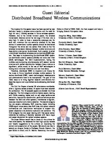
Fig. 7. Simulated (a)–(c) and measured (d)–(f) radiation patterns of the proposed lens antenna at 12, 15, and 18 GHz, respectively.
The simulated near-field results are shown in Fig. 4, in which Fig. 4(a) and (b) demonstrate that the spherical waves from the horn antenna are transformed to plane waves by the lens, and the electric field distributions in the E-plane and the H-plane are identical as expected. Fig. 4(c) shows that the amplitude distribution on the lens aperture agrees very well with the Taylor circular array distribution, whilst Fig. 4(d) illustrates that the phase front distributes quite uniformly except on the lens edges. We observe that there are slight fluctuations for both amplitude and phase of aperture field. They are attributed to the reflected waves in the GRIN lens accomplishing with the main refraction waves. It is also noted that the phase front in the H-plane is less uniform than that in the E-plane. This is mainly because the phase centre in the H-plane of the feed is slightly different from that in the E-plane. Furthermore, the variation of the phase front on the edge may slightly harm the directive performance. However, since most energy is guided to the central part where the phase is almost uniform, the lens still has great directivity, as will be demonstrated in the later discussions. To realize the broadband lens antenna, MTMs with a broad operating band are needed. In our experiment, two kinds of MTM unit cells based on drilled-hole dielectrics are adopted: one is with a thickness of 1 mm to realize the refractive index of the IMLs, and the other is with a thickness of 2 mm to realize that of the core layers. Due to the centrosymmetric property of the structure, the drilled-hole unit cells are insensitive to the polarization of the incidence and, therefore, are able to construct near-isotropic MTMs [4]. In addition, these kinds of MTMs are able to operate in broadband because they present non-resonant characteristics when the operating frequency is far away from their resonance frequency. As shown in Fig. 5, the horizontal dimension of a unit cell is 2 2 mm . The refractive index of the MTM unit cells covers all the required values ranging from 1.1 to 1.627. The frequency responses of refractive index for the drilled holes are shown in Fig. 5(c) and (d). The refractive index of the drilled-hole dielectric with different hole diameters almost remains constant within the Ku band, which guarantees the lens working in broadband.
A prototype MTM lens operating at the Ku band with low side-lobes and high gain is constructed using the drilled-hole dielectrics, as illustrated in Fig. 6. The dielectric of unit cell is F4B, whose permittivity is 2.65 with nominal loss tangent 0.001 at 10 GHz. The drilled-hole dielectrics are adopted to realize the refractive index from 1.1 to 1.627. We remark that the refractive index smaller than 1.1 in the gradientindex lens are all chosen as 1.1 approximately. The total thickness of the lens and the aperture diameter are mm and mm, respectively. The thicknesses of the two IMLs are both 4 mm. The focal distance is mm. The lens is composed of 4 pieces of IMLs and 48 pieces of core layers. The comparison of simulated and measured radiation patterns of the proposed lens antenna is shown in Fig. 7. The simulated radiation patterns at three sample frequencies 12, 15, and 18 GHz are demonstrated in Fig. 7(a)–(c), respectively. We notice that the gains are 26.3, 28.1 and 29.8 dBi at these frequencies, respectively, and their corresponding aperture efficiencies are higher than 67.6%, 65.5% and 67.2%, respectively, since there is intrinsic loss of the MTMs. The dB in both E- and H-planes. Hence, the side-lobes are all below proposed MTM lens antenna has very good performance to balance the high gain and low side lobes. Fig. 7(d)–(f) present the corresponding measured radiation patterns. It is observed that the measured patterns have good agreements with the simulated ones with slight losses of gains and side-lobes, which is mainly due to the approximation of less-than-1.1 refractive indices because it disturbs the aperture field distribution through grazing incidence. Finally, the measured aperture efficiencies are higher than 59.3%, 58.7%, and 55.3%, respectively. It is noted that the measured efficiencies are weaker than the simulated ones. This is mainly due to the reason that the dielectric loss within Ku band in the experiment is higher than that in the simulation. Fig. 8 illustrates the simulated and measured voltage standing wave ratio (VSWR). It is obvious that the VSWRs are always below 1.6 across the whole Ku band, which shows very good matching to the free space. The measured VSWR is slightly higher than the simulated one, which may be caused by the inaccuracy during fabrication and assembly.
IEEE TRANSACTIONS ON ANTENNAS AND PROPAGATION, VOL. 61, NO. 11, NOVEMBER 2013
5797
TABLE I PARAMETERS OF LENS 1, LENS 2, LENS 3, AND LENS 4
IV. CONCLUSION
Fig. 8. The simulated and measured VSWR of the proposed lens antenna.
In this communication, a new approach to control radiation patterns in broadband by manipulating the aperture field distributions with both the amplitude and the phase has been introduced. The flexibility and applicability of the method has been illustrated by four lenses with different aperture amplitude distributions but uniform phase distribution. For verification, one of the broadband MTM lens antennas with controllable radiations has been successfully designed, fabricated and measured. The proposed antenna exhibited low sidelobes and considerably high gain across the whole Ku-band. Therefore, the method easy in realization and low in cost can be generalized to significantly improve the performance of a set of microwave and optical antennas.
REFERENCES
Fig. 9. Simulated aperture field distributions for different lenses. (a) The amplitudes of aperture fields. (b) The phases of aperture fields. (c) The near-field distribution of lens 1. (d) The near-field distribution of lens 4.
To further investigate the flexibility of manipulating the EM fields using MTMs, another three lens antennas with different field distributions on the apertures are examined. For convenience, they are named as lens 1, 2, and 4, respectively. Note that lens 3 represents the aforementioned fabricated lens. The feeds, focal lengths, and aperture sizes of lenses 1, 2, and 4 are the same as those of lens 3. In contrast, the and refractive-index distributions lenses have different thickness (characterized by ), as listed in Table I. The simulated amplitude and phase distributions of the aperture fields are shown in Fig. 9. It is observed that quite different amplitude distributions are achieved while the four phase fronts remain similarly flat (especially in the central part). Fig. 9(c) illustrates the near-field distribution of lens 1 which is similar to the uniform distribution, whilst Fig. 9(d) illustrates the near-field distribution of lens 4 which is a typical tapered distribution with most energy assembling in the centre region. Therefore, the method introduced in this work demonstrates the feasibility of manipulating the amplitude and the phase of aperture field simultaneously through controlling the refractive index distribution of the MTM lens.
[1] J. Kraus, Antennas. New York, NY, USA: McGraw-Hill Education, 1988. [2] R. K. Luneburg, Mathematical Theory of Optics. Berkeley, CA, USA: Univ. California Press, 1964. [3] N. Kundtz and D. R. Smith, “Extreme-angle broadband metamaterial lens,” Nature Mater., vol. 9, pp. 129–132, Feb. 2010. [4] H. F. Ma and T. J. Cui, “Three-dimensional broadband and broad-angle transformation-optics lens,” Nature Commun., vol. 1, Nov. 2010. [5] Metamaterials—Theory, Design, and Applications, T. J. Cui, D. R. Smith, and R. Liu, Eds. New York, NY, USA: Springer, 2009. [6] U. Leonhardt, “Optical conformal mapping,” Science, vol. 312, pp. 1777–1780, Jun. 23, 2006. [7] J. B. Pendry, D. Schurig, and D. R. Smith, “Controlling electromagnetic fields,” Science, vol. 312, pp. 1780–1782, Jun. 23, 2006. [8] D. Schurig, J. J. Mock, B. J. Justice, S. A. Cummer, J. B. Pendry, A. F. Starr, and D. R. Smith, “Metamaterial electromagnetic cloak at microwave frequencies,” Science, vol. 314, pp. 977–980, Nov. 10, 2006. [9] J. S. Li and J. B. Pendry, “Hiding under the carpet: A new strategy for cloaking,” Phys. Rev. Lett., vol. 101, Nov. 14, 2008. [10] R. Liu, C. Ji, J. J. Mock, J. Y. Chin, T. J. Cui, and D. R. Smith, “Broadband ground-plane cloak,” Science, vol. 323, pp. 366–369, Jan. 16, 2009. [11] J. Valentine, J. S. Li, T. Zentgraf, G. Bartal, and X. Zhang, “An optical cloak made of dielectrics,” Nature Mater., vol. 8, pp. 568–571, Jul. 2009. [12] H. F. Ma and T. J. Cui, “Three-dimensional broadband ground-plane cloak made of metamaterials,” Nature Commun., vol. 1, Jun. 2010. [13] Y. Lai, J. Ng, H. Y. Chen, D. Z. Han, J. J. Xiao, Z. Q. Zhang, and C. T. Chan, “Illusion optics: The optical transformation of an object into another object,” Phys. Rev. Lett., vol. 102, Jun. 26, 2009. [14] W. X. Jiang, H. F. Ma, Q. Cheng, and T. J. Cui, “Illusion media: Generating virtual objects using realizable metamaterials,” Appl. Phys. Lett., vol. 96, Mar. 22, 2010. [15] M. Rahm, S. A. Cummer, D. Schurig, J. B. Pendry, and D. R. Smith, “Optical design of reflectionless complex media by finite embedded coordinate transformations,” Phys. Rev. Lett., vol. 100, Feb. 15, 2008. [16] W. X. Jiang, T. J. Cui, Q. Cheng, J. Y. Chin, X. M. Yang, R. P. Liu, and D. R. Smith, “Design of arbitrarily shaped concentrators based on conformally optical transformation of nonuniform rational B-spline surfaces,” Appl. Phys. Lett., vol. 92, Jun. 30, 2008. [17] W. X. Jiang, C. Y. Luo, H. F. Ma, Z. L. Mei, and T. J. Cui, “Enhancement of current density by DC electric concentrator,” Sci. Rep., vol. 2, Dec. 11, 2012.
5798
IEEE TRANSACTIONS ON ANTENNAS AND PROPAGATION, VOL. 61, NO. 11, NOVEMBER 2013
[18] H. Y. Chen and C. T. Chan, “Transformation media that rotate electromagnetic fields,” Appl. Phys. Lett., vol. 90, Jun. 11, 2007. [19] E. E. Narimanov and A. V. Kildishev, “Optical black hole: Broadband omnidirectional light absorber,” Appl. Phys. Lett., vol. 95, Jul. 27, 2009. [20] Q. Cheng, T. J. Cui, W. X. Jiang, and B. G. Cai, “An omnidirectional electromagnetic absorber made of metamaterials,” New J. Phys., vol. 12, Jun. 3, 2010. [21] Alu, M. G. Silveirinha, A. Salandrino, and N. Engheta, “Epsilon-nearzero metamaterials and electromagnetic sources: Tailoring the radiation phase pattern,” Phys. Rev. B, vol. 75, Apr. 2007. [22] R. B. Greegor, C. G. Parazzoli, J. A. Nielsen, M. A. Thompson, M. H. Tanielian, and D. R. Smith, “Simulation and testing of a graded negative index of refraction lens,” Appl. Phys. Lett., vol. 87, Aug. 29, 2005. [23] E. W. Marchand, Gradient Index Optics. London: Academic, 1978. [24] Z. L. Mei, J. Bai, T. M. Niu, and T. J. Cui, “A half maxwell fish-eye lens antenna based on gradient-index metamaterials,” IEEE Trans. Antennas Propag., vol. 60, pp. 398–401, Jan. 2012. [25] D. R. Smith, J. J. Mock, A. F. Starr, and D. Schurig, “Gradient index metamaterials,” Phys. Rev. E, vol. 71, Mar. 2005. [26] X. Chen, H. F. Ma, X. Y. Zou, W. X. Jiang, and T. J. Cui, “Three-dimensional broadband and high-directivity lens antenna made of metamaterials,” J. Appl. Phys., vol. 110, Aug. 15, 2011. [27] U. Sangawa, “Gradient index lens antennas with controllable aperture field distributions,” IEICE Trans. Commun., vol. E95b, pp. 2051–2058, Jun. 2012. [28] M. Q. Qi, H.-X. Xu, H. F. Ma, M. P. Jin, W. Wang, and T. J. Cui, “A wideband waveguide antenna with nearly equal E- and H-plane radiation patterns,” Int. J. Antennas Propag., vol. 2013, p. 608393, 2013. [29] M. Clerc and J. Kennedy, “The particle swarm—Explosion, stability, and convergence in a multidimensional complex space,” IEEE Trans. Evol. Comput., vol. 6, pp. 58–73, Feb. 2002.
UHF Stacked Hilbert Antenna Array for Partial Discharge Detection Jian Li, Peng Wang, Tianyan Jiang, Lianwei Bao, and Zhiman He
Abstract—This communication proposed an ultra-high frequency (UHF) stacked Hilbert antenna array to broaden bandwidth and increase gain of Hilbert fractal antenna. Two parasitic curves were added to improve the third order Hilbert curve and stacked structure was applied to the new antenna element. The UHF stacked Hilbert antenna was designed as 2 elements and fed by the Wilkinson’s antenna array that involved 2 four-way power divider. Measurement results show that the UHF stacked Hilbert antenna array achieves a maximum gain of 1 dBi and exhibits a wide impedance bandwidth. Actual partial discharge (PD) experiments were carried out for typical artificial insulation defect models, while the proposed antenna array and an existing Hilbert fractal antenna were both used for PD measurements. The proposed antenna array was superior in this respect and effective for UHF online monitoring of PDs in electrical apparatus. Index Terms—Hilbert curve, parasitic curves, partial discharge (PD), power divider, stacked structure, UHF stacked Hilbert antenna array.
I. INTRODUCTION Partial discharge (PD) online monitoring is an effective method in inspecting insulation defects and fault diagnosis in electrical apparatus, such as transformers, gas-insulation switches, wind power devices, etc. However, detection of pre-discharge in wind power transformer and generator using traditional PD detection approaches is difficult. Compared with traditional PD detection methods, the ultra-high frequency (UHF) PD detection technology has advantages that include strong anti-interference, high sensitivity, etc., which make it more suitable for PD online monitoring, particularly pre-discharge and tiny PD in wind power apparatus. The design of UHF antenna is the key technology in the UHF detection approaches because the performance of UHF antenna determines the ability of the PD online detection systems. Compared with the antennas in communication application, the design of the compact antenna in PD detection is more complex because the resonant frequencies of the antenna are required to fall into the range between 300 and 1000 MHz. The UHF antennas used in PD detection can be divided into two kinds: external and built-in antenna. The external antenna includes horn antenna [1], two-wire Archimedian spiral antenna [2], etc. The built-in antenna involves disc sensor [3], probe antenna [4], Hilbert fractal antenna [5], etc., which has advantages, such as strong anti-interference and high sensitivity. The compact third order Hilbert antenna has been well used for PD detection [5]. Obtaining high gain and wide bandwidth with single element has been a challenge for Hilbert antenna. In the recent years, many efforts have been made to increase the gain and bandwidth of microstrip antenna. Literatures [6] highlighted that
Manuscript received October 24, 2012; revised May 21, 2013; accepted July 15, 2013. Date of publication August 02, 2013; date of current version October 28, 2013. This work was supported by the fund of National Basic Research Program of China (973 Program, 2012CB215205), the National Natural Science Foundation of China (No. 51021005, 51177180), and the doctoral program of higher education of China (20110191130004). The authors are with the State Key Laboratory of Power Transmission Equipment & System and New Technology, Chongqing University, Chongqing 400044, China (e-mail:
[email protected]). Color versions of one or more of the figures in this communication are available online at http://ieeexplore.ieee.org. Digital Object Identifier 10.1109/TAP.2013.2276453 0018-926X © 2013 IEEE