TCP connections using default window sizes and propose ... The TCP maximum window size is limited by default to .... RAM running Windows NT 4.0 Server.
TCP/IP OVER ATM BASED HFC SYSTEMS J. D. Angelopoulos (2), A. Grilo (1), M. S. Nunes (1), T. G. Orphanoudakis (2) (1) INESC, Portugal. (2) National Technical University of Athens, Greece. ABSTRACT The introduction of fiber to CATV systems can improve noise figures and at the same time expedite the introduction of a return channel to enable support of interactive services. The role of TCP/IP in such services is currently dominant and the efficient support of these widespread protocols is important for cost-effective utilization of the infrastructure. This paper investigates the issues arising from the support of TCP/IP in the peculiar HFC environment and proposes solutions for improved performance. INTRODUCTION HFC (Hybrid Fiber Coax) networks are a promising access solution for the introduction of broadband services to residential users in a cost-effective way. The attractiveness of HFC systems for the delivery of broadband services lies in the high reuse of existing infrastructure and a sound gradual upgrade strategy. The initial investment mainly consists in the incorporation of a return channel and fiber feeders to customer clusters of a few hundred homes. Sharing the common feeder and cable in the upstream direction (from stations to head-end) requires a MAC protocol to allocate slots to stations in a TDMA fashion. The legacy topology is that of a broadcast tree and branch. One feeder fiber per such node is envisaged creating the HFC architecture. Future needs can be accommodated by further breaking down the clusters by means of more fiber feeders towards 100 homes. The cable can offer to the new services the range between 450Mhz to 750Mhz for the downstream direction and the range from 5 to 35 Mhz for the upstream. Standardization bodies foresee the implementation of all applications over the ATM layer [1], [2]. TCP/IP based services such as Internet access will be the main paradigm for interactive services. The high bandwidth-delay product and the mismatch in bandwidth as is the HFC case, may result in reduced efficiency. The objective of this paper is to investigate on the parameters that may affect the performance of TCP based applications over HFC networks, expose the inefficiency caused by the asymmetry in the case of TCP connections using default window sizes and propose possible solutions offering higher throughput. TCP EFFICIENCY OVER HFC NETWORKS Implications of the high bandwidth-delay product Protocols such as TCP were created taking into account low bandwidth environments. When using these protocols over ATM, in HFC networks several
adaptations must be made to achieve maximum efficiency. When TCP functions over broadband access networks such as HFC, then the parameters of the network must be taken into account namely the high bandwidth (around 30 Mbps for the downstream and 2 Mbps for the upstream) and the delay (apart from propagation delay a significant access delay due to the multiplexing action of the MAC protocol). However, we must not forget that what really matters is the final performance at the application level, i.e. we must know what does transport efficiency really mean to application performance. The TCP maximum window size is limited by default to 64KByte. In high bandwidth and high delay networks this turns to be inefficient, as much time is spent waiting for packet acknowledgements. The effect is that the average used bandwidth is somewhat lower than the available network bandwidth. In a connection, maximum efficiency is obtained when there are no idle times between new transmissions, as data is being carried by every portion of the network sending path, while acknowledgement packets fill the reverse path In an IP network we must also account for queuing at the routers. The total unacknowledged data at the sender’s perspective (TCP maximum window size) is W=B*D, in which B is network bandwidth and D is the round trip delay. In an IP network, D is calculated as D=2*Tprop+2*Trout, where Tprop is the propagation delay and Trout is the mean packet delay at the routers with no congestion. Trout includes route processing and queueing delays. Tprop=2*L*τ, where L is the length between sender and receiver and τ is the propagation delay per unit length. For big distances Trout turns to be the most important component of D, reaching values of a few seconds. Unfortunately it depends very much on load and hop distance, being difficult to make an accurate estimate. Inside the HFC a typical propagation delay of 5 µsec/m is considered [2] and the mean access delay for typical MAC protocols may reach several tens of milliseconds. The distance of HFC terminals from the Head End Bandwidth (Mbit/s) RTT (ms) 20 100 200 500 1000 1500 2000
10
25
50
155
622
24 122 244 610 1220 1831 241
61 305 610 1526 3051 4577 6103
122 610 1220 3052 6103 9155 12207
378 1893 3784 9461 18921 28382 37842
1517 7595 15183 37967 75927 113894 151855
TABLE 1: TCP window size in KBytes, relative to round trip delay and bandwidth.
ranges from hundreds of meters to several kilometres. Thus the round trip delay depend on the traffic load inside the HFC and on the distance of the transmitter from the head-end. Table 1 presents the values of W for several values of B and D. As we can see, for a bandwidth of 25Mbps and a round trip delay above 20 milliseconds, which is a typical case in HFC networks, an increase of the maximum TCP window size is required, to achieve maximum throughput and keep the downstream channel filled with data. As access delay ca typically take hundreds of milliseconds, this requirement is of importance. Implications of the asymmetric links. Because of the asymmetry in HFC networks, the acknowledgements for packets transmitted in the high rate downstream channel must be sent via the low rate upstream channel. In order to keep up with the downstream rate, a valuable portion of the upstream capacity will be wasted for acknowledgement packets. For example when accessing a Web server and downloading a large file, data will be transmitted at high speed (depending on competing traffic this could reach up to 30 Mbps) through the downstream channel and acknowledgements will occupy most of the (3 Mbps) upstream capacity. Moreover the absence of upstream data to carry piggybacked acknowledgements (a mechanism which is anyway seldom used [3]) especially for such highly asymmetric services leaves no alternative but the generation of acknowledgement packets to be transmitted upstream. In addition these packets will participate in the MAC process causing added delay in other upstream traffic. This would have two undesirable effects in HFC systems: the achievable downstream throughput is restrained by the slow return of acknowledgements needed to advance the sliding window and the narrow upstream channel is flooded by acknowledgements (It is worth noting that this is further aggravated by the problem of RM cell loopbacks in the case of ABR traffic [4]). Because of the great fluctuation of the traffic, frequent even though transient, overloads will occur at the peak hours in the return path. To expose the problem of asymmetry we evaluate the traffic of acknowledgements that will be generated when the downstream channel is used for down-loading data of a TCP/IP application using Classical IP over Encapsulation method LLC/SNAP Encapsulation Null Encapsulation
ACK/DATA Packet size (bytes) 40/576 40/1200 40/9180 40/576 40/1200 40/9180
ACK/DATA ATM layer (bytes) 106/689 106/1378 106/10388 53/689 53/1378 53/10388
Up/Down (Mbps) 4,6/30 2,3/30 0,01/30 2,3/30 1,1/30 0,005/30
TABLE 2: Upstream traffic generated for control traffic only for several cases of encapsulation methods and MSS
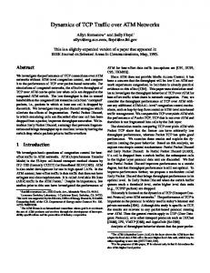
ATM at a rate of 30 Mbps. The values included in Tab. 1 are computed assuming either LLC/SNAP or null encapsulation of IP packets [6], [7]. Obviously the LLC/SNAP encapsulation proposed in RFC 1483 and RFC 1577 further aggravates the problem causing considerable bottleneck in the upstream channel. Another important parameter is the Maximum Segment Size (MSS) of the TCP packets. In case of small TCP segments the overhead of TCP acknowledgements will be tremendous leaving no available band-width for upstream transmission Application level performance Network features are not the only aspects to affect application performance. The terminal’s software can also introduce significant processing overhead. Fig. 1 shows the main network and terminal timing overheads that impact performance at the application level in one communication direction. A p p lic a tio n A P Is and d riv er stacks
A p p lic a tio n
T to
N IC
A P Is and d rive r sta ck s N IC
Tp N e tw o rk D /2 T to = T erm in a l o v e rh e a d T p = P a c ke t tim e
D = R o u n d trip d e la y
Figure 1: Application timing overheads Tto is the overhead introduced by software processing. The time required to send/receive a packet to/from the network is Tp=P/B where P is the packet length (PDU overhead introduced by protocol control fields is not considered) and B is the network bandwidth. Finally, the network round trip delay is D. At the application level, the total time taken for a single message to reach the receiver is given by Tt=(Tto+Tp+D/2). In order to draw some conclusions on the relevance of these overheads, we tested an echo client/server application in order to obtain Tt and hence Tto. The testing environment comprised the following: Client/Server PC platforms used: Client: 120MHz Pentium with 32MB RAM running Windows NT 4.0 Server, Server: 166MHZ Pentium with 32MB RAM running Windows NT 4.0 Server. ForeRunnerLE 25Mbps ATM adapters were used in both PCs. ForeThought 4.1 drivers are used in ForeRunnerLE adapters. Default configuration of Classical IP over ATM adapter, which defines an MTU of 9180 bytes, as recommended by RFC 1577.
Switched Virtual Circuits were used, the ATM adapters being connected through a ForeRunner ASX−200WG ATM switch. Winsock 2.2 applications using TCP. As the distance was short, we can consider D≈0 so Tto was calculated as Tto=Tt-Tp. Tab. 3 shows the results for several packet sizes. Tab. 4 presents the expected values of Tt when D is increased as a consequence of routing and propagation in real networks. Packet size (bytes) 256 1024 4096 8192 9180 16K 32K 64K
Tt (ms) 0.9 1.2 2.8 4.8 5.4 7.7 14.0 26.4
Tp (ms) 0.1 0.3 1.3 2.6 2.9 5.1 10.2 20.5
Tto (ms) 0.8 0.9 1.5 2.2 2.5 2.6 3.8 5.9
From the above results we can conclude that D is the main factor to impact application performance. The value of 1000 milliseconds is typical of access distances of 2000 Km and above. This relevance decreases with packet length, while Tp behaves exactly the opposite. The non-linearity exhibited by Tto is probably due to superposition of software processing and line transmission of large packets, due to fragmentation. It is worth noting that these results were achieved in isolated packet transmission, and thus present typical patterns for highly interactive operations such as those presented by Telnet and VoD user control. Although in client/server systems Tto is higher due to processing and IO access at the server, it never surpasses the tens of milliseconds, usually irrelevant for distances above 1000 Km. The performance of bulk data transfer like FTP, VoD and multimedia WWW downstream traffic depends more on bandwidth and TCP efficiency.
TABLE 3: TCP application overheads in local ATM environment Packet size (bytes) 256 1024 2048 4096 8192 9180 16K 32K 64K
20 20.9 21.2 21.8 22.8 24.8 25.4 27.7 34.0 46.4
100 96% 94% 92% 88% 81% 79% 72% 59% 43%
100.9 101.2 101.8 102.8 104.8 105.4 107.7 114.0 126.4
D/2 (milliseconds) 500 99% 500.9 99% 501.2 98% 501.8 97% 502.8 95% 504.8 95% 505.4 93% 507.7 88% 514.0 79% 526.4
100% 100% 100% 99% 99% 99% 98% 97% 95%
1000 1000.9 100% 1001.2 100% 1001.8 100% 1002.8 100% 1004.8 100% 1005.4 99% 1007.7 99% 1014.0 99% 1026.4 98%
TABLE 4: Expected values for Tt on TCP application packet transmission, in ms. Percentages stand for the fraction of D/2. TECHNIQUES TO IMPROVE PERFORMANCE OF TCP/HFC Selective acknowledgement dropping and TCP spoofing in HFC Obviously if we want to relieve the upstream channel from the overhead of excessive acknowledgements we come up to the solution of ‘Selective Acknowledgement Dropping’. This technique has already been implemented in hybrid asymmetric networks with a satellite link for downstream transmission and public telephone networks at modem speeds to provide the upstream communication path [5]. This is feasible because the TCP acknowledgement scheme is cumulative. That means that each acknowledgement reports how much of the stream has accumulated and which is the octet the receiver expects next. So lost acknowledgements do not necessarily force retransmission [3]. In a highly reliable network as HFC we can omit transmitting acknowledgements for some of the intermediate packets if necessary in order to save upstream bandwidth which is at premium. As long as it is not compelling to acknowledge each and every one of the received packets the HFC terminal could selectively drop some of the acknowledgements generated by TCP when needed. The less complicated way is to enforce
this action at the interface between TCP and the underlying network. Assuming for example the case where a terminal is attached to the HFC termination point via an ATM Network Interface Card (NIC) the mechanism we mentioned could take place at the NDIS Driver of the NIC that should be appropriately modified. This scheme is illustrated in figure 2. Although the technique described in fig. 2 is oriented towards the Windows OS it could be implemented in any case. Development of a special layer between the TCP/IP and the underlying network interface could be done independently of the terminal’s operating system. The option of where to implement the Selective Acknowledgement Dropping technique depends on the operational constraints. Thus in the Windows OS case a special layer between the TCP/IP and the CLIP driver could be implemented with an 'Intermediate NDIS driver'. This would offer a connectionless interface on both sides in order to adapt to the CLIP interface. If developing a special ATM driver to be used in HFC environments is feasible this technique could also be implemented in the ATM driver. The technique of Selective Acknowledgement Dropping might relieve the upstream channel of transmissions that could be avoided making use of the cumulative acknowledgement mechanism of TCP but can not avoid the implications with the sliding window mechanisms.
APPLICATION TCP ACK 4101 ACK 3101 ACK 2101 ACK 1101 ACK 101
Special Driver
SELECTIVE ACKNOWLEDGEMENT DROPING
ACK 3101 ACK 2101 ACK 1101
ACK 4101 ACK 101
AAL5 ATM PHY
TCP SPOOFING
UNIHome
Buffer
UNIHFC
WINmax
TCP/IP H/E
Internet WIND
HFC Network
TCP/IP Internet
Figure 2. Selective Acknowledgement Dropping & TCP Spoofing The sliding window mechanism together with the timer set for each packet transmitted are used to detect excessive delays and loss of packets. If an acknowledgement is lost or arrives too late, i.e. after the timer has expired, the packet is considered lost and the window stops sliding forth. When the window also expires and unacknowledged packets still exist, retransmission is triggered leading to lower throughput and utilization of the channel. The dominant factor in selecting the window size is the bandwidth-delay (B*D) product of the network. The current default TCP window size of 64 Kbytes is considered small even for the 25 Mbits HFC environment as was mentioned above. The throttling of acknowledgement packets in order to relieve the upstream channel from overhead could then lead to frequent expiration of both the sliding window and the timer. This in turn would cause long idle periods in the downstream channel and trigger excessive re-transmissions leading to decreased throughput in the downstream channel. The throughput in this case is determined by the window size, which must be finely tuned. We also make the assumption in this case that we can’t change the window size to a larger value. The restriction to accept the current default window size of TCP protocol stands in order to not affect the operation of commercial off-the-self S/W products and achieve inter-working with TCP/IP Internet. A way to further improve utilization of the downstream channel and increase throughput would be to transparently split the end-to-end TCP connections at the Head End. This alternative is also presented in fig. 2. As can be seen in fig. 2 the TCP connection has been split in two parts at the Head End which is the junction point between the asymmetric HFC network and the TCP/IP Internet. In this case the connection between the HFC terminal and the Head End can take place
unaffected by the default TCP window size. The implementation of TCP at the Head End and for the HFC side could provide a large enough window to make up for the dropped acknowledgements. The communication of the Head End and the Internet server on the other hand will make use of the default window size of the TCP protocol stack of the Internet server and the Head End can be configured so that acknowledgements will be generated at the highest rate in order to keep the server busy and the network saturated with data leading to higher throughput and utilization of the network. This technique has also been implemented in hybrid Satellite/Public Telephone networks where the need for splitting the TCP connection (a technique called ‘TCP spoofing’ [5]) is more prominent given the fact of high round trip delay because of the satellite link. Internet encapsulation Another approach, in order not to interfere with the NDIS driver of the card nor to implement complicated ad hoc solutions at the head-end is to try to eliminate overhead as much as possible, in order to make the best use of the available bandwidth. Most overhead of Internet traffic over ATM is introduced by IP encapsulation. Although commercial solutions implement RFC 1577 (following RFC 1483 LLC/SNAP or Null Encapsulation), there are some trends towards eliminating IP and to encapsulate transport PDUs directly in AAL5 (TULIP and TUNIC) [6], [7], [8]. This paragraph describes the encapsulation methods presented by IETF, and evaluates their impact in bandwidth efficiency. RFC 1932 refers four methods for Internet encapsulation in ATM. As will be seen, each method represents a compromise between set-up time information and encapsulation overhead, as all the IP
information that cannot be established during ATM setup must be carried in all data PDUs. Of these methods, LLC/SNAP Encapsulation and Null Encapsulation are standardised in RFC 1483, while TULIP and TUNIC are simply referred in RFC 1932. LLC/SNAP Encapsulation. This method is the most popular in commercial systems. It requires a VC to be established between two layer-2 LLC entities, allowing multiplexing of several layer-3 protocols in the same VC, which is suitable when VC set-up is not easy. The first three octets of the LLC header (equal to 0xAA-AA03) specify that the packet belongs to a non-ISO routable protocol, and that a SNAP header follows. The first field of the SNAP header, OUI (Organisationally Unique Identifier) equal to 0x00-00-00 means that the following field is an Ethertype PID (Protocol Identification), in this case denoting an IP payload (equal to 0x08-00). During VC set-up, the LLC entity must be properly identified in the BLLI field of the SETUP message. Null Encapsulation. This method requires a VC to be established for each pair of layer 3 entities in both machines, hence allowing layer-3 PDUs to be exchanged with no added overhead. As each VC denotes a unique layer-3 entity, the SETUP message must include the layer 3 identification in the BLLI field. 1. TULIP (TCP and UDP over Lightweight IP). During an IP session using Null Encapsulation, most fields of the IP header have the same value in all IP datagrams. The only exception is the protocol identification field, which can be either TCP or UDP, as transport protocol multiplexing is allowed. This suggests that this is the only field that must be carried in all PDUs. The remaining session information can be established at set-up time. Besides the BLLI field, which is equal to Null Encapsulation, source and destination IP addresses must be carried by the SETUP message, for example in the Calling and Called Party Subaddress IEs, respectively. TULIP can be seen as a more efficient alternative to Null Encapsulation. TUNIC (TCP and UDP over Nonexistent IP). This method goes a step further than TULIP, eliminating all IP overhead from data PDUs. The ATM connection is established between layer-4 entities (in this case TCP or UDP), and as such only layer-4 PDUs are exchanged, it does not allow layer-4 protocol multiplexing, as the layer-4 protocol is identified at set-up time, together with the layer-3 protocol, source and destination IP addresses. Another variant of this approach would establish source and destination layer-4 ports during setup, assigning a VC for each layer-4 session. Overhead of tcp acknowledgements. As already mentioned, upstream bandwidth efficiency is a major concern, as it is expected that most of it will be occupied with TCP acknowledgement PDUs. Tab. 5 shows the overhead per TCP acknowledgement PDU, presented by Internet encapsulation methods. LLC/SNAP Encapsulation presents the double overhead of the other methods, as it needs 2 cells per TCP acknowledgement PDU, while the other methods need
only 1 cell. Nevertheless, LLC/SNAP is the only one that allows layer-3 protocol multiplexing in the same VC, making it the mostly used in commercial systems. Besides eliminating layer-2 encapsulation, TULIP and TUNIC remove the overhead introduced by IP headers in data PDUs. Nevertheless, as layer-3 session parameters are established during ATM connection setup, they introduce the problem of mapping this information in ATM signalling. Encaps/on Method LLC/SNAP. Null. TULIP TUNIC
TCP+IP header (bytes) 20+20 20+20 20+1 20+0
LLC/SNAP Header (bytes) 8
CPCS5 Trailer (bytes) 8 8 8 8
Total length cells 2 1 1 1
TABLE 5: Length of TCP Acknowledge AAL5 PDU for the several Internet encapsulation methods. CONCLUSIONS HFC systems present certain peculiarities when TCP/IP based services are offered through them which need some attention to avoid excessive inefficiencies. The higher bandwidth-delay product of HFC systems compared with current lower rates, requires a higher TCP window size to preserve high utilization. The asymmetric rates necessitated for other system reasons can result in a bottleneck in the narrow upstream channel. Introducing a selective drop of acknowledgements at the head-end can improve the overall efficiency. Acknowledgement: This work was partially funded by the ACTS project AC037 ATHOC dealing with the development of an HFC system. References: 1. L.F. Wojnaroski, "Baseline text for the Residential Broadband Sub-working group," ATM Forum Doc. No.ATMF95-0458R1, Aug.1995.c 2. Draft of IEEE802.14 standard Draft2 R2 (not publicly available) 3. Comer, D.E (1991), “Internetworking with TCP/IP Vol. I: Principals and Architecture”, 2nd edition, Prentice Hall, Englewood Cliffs, New Jersey 4. J. D. Angelopoulos, T. G. Orphanoudakis "Control of Traffic Accessing ATM Core Networks via HFC Systems", NOC’97, June 1997, Antwerp. 5. V. Arora, N. Suphasindhu, J. S. Baras, D. Dillon, “Effective extensions of Internet in hybrid satelliteterrestrial networks”, available at http://www.isr.umd.edu/TechReports/CSHCN/1996 6. J. Heinanen, “Multiprotocol Encapsulation over ATM Adaptation layer 5”, RFC 1483, Telecom Finland, July 1993. 7. M. Laubach, “Classical IP and ARP over ATM”, RFC 1577, Hewlett-Packard Laboratories, January 1994. 8. R. Cole, R. Shur, “IP over ATM: A Framework Document”, RFC 1932, AT&T Bell Laboratories, April 1996.