Section II presents design rules for building a robot that can recover from collisions. ... such spherical rollcages provide a good starting point for designing impact .... In a later stage, the use of miniature force sensors around the structure of the ...
The AirBurr: A Flying Robot That Can Exploit Collisions Adrien Briod*, Adam Klaptocz*, Jean-Christophe Zufferey and Dario Floreano
Abstract—Research made over the past decade shows the use of increasingly complex methods and heavy platforms to achieve autonomous flight in cluttered environments. However, efficient behaviors can be found in nature where limited sensing is used, such as in insects progressing toward a light at night. Interestingly, their success is based on their ability to recover from the numerous collisions happening along their imperfect flight path. The goal of the AirBurr project is to take inspiration from these insects and develop a new class of flying robots that can recover from collisions and even exploit them. Such robots are designed to be robust to crashes and can take-off again without human intervention. They navigate in a reactive way, bump into obstacles, and unlike conventional approaches, they don’t need heavy modeling in order to fly autonomously. We believe that this new paradigm will bring flying robots out of the laboratory and allow them to tackle unstructured, cluttered environments. This paper aims at presenting the vision of the AirBurr project, as well as the latest results in the design of a platform capable of sustaining collisions and self-recovering after crashes. Index Terms—Robust bio-inspired indoor flying robot.
I. INTRODUCTION Flying robots have unique advantages in the exploration and surveillance of indoor environments presenting dangers to humans, such as caves, semi-collapsed buildings or radioactive areas. Flight as indoor locomotion is interesting because it is not constrained by the morphology of the ground and can be used to navigate over obstacles more efficiently than ground-based locomotion. Current flying systems however have difficulty in dealing with the large amount of obstacles inherent to such unknown environments. Collisions with this ’clutter’ generally result in crashes from which the platform can no longer recover. Many researchers thus focus on obstacle detection (using mechanisms ranging from optic flow [1], IR range sensors [2] or lasers [3]) and try to avoid collisions at all costs. However, the lack of global positioning (like GPS) and the unstable nature of flying platforms render this task increasingly difficult as the complexity of the environment increases, requiring advanced sensors, powerful processors and extensive modeling of the environment. As an example, All authors are with the Laboratory of Intelligent Systems, Ecole Polytechnique F´ed´erale de Lausanne, 1015 Lausanne, Switzerland. Contact e-mail: [adrien.briod|adam.klaptocz]@epfl.ch. This work was supported by Armasuisse, competence sector Science + Technology for the Swiss Federal Department of Defense, Civil Protection and Sports. This research was supported by the Swiss National Science Foundation through the National Centre of Competence in Research Robotics. *Adrien Briod and Adam Klaptocz contributed equally to this work.
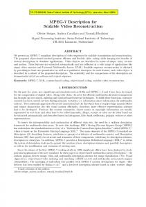
Fig. 1. The AirBurr robot (depicted in the above artist’s impression) will be able to explore cluttered indoor environments autonomously. A contactsensitive structure allows the robot to navigate around obstacles by flying away from them once it touches them. During collisions, the structure protects the robot from damage. If the robot falls to the ground, it can actively upright itself thanks to its legs and take off again without human intervention.
the most advanced and successful method to date is the simultaneous localization and mapping (SLAM) approach, which allows absolute positioning in a map built by the system itself using high-precision on-board sensors. SLAMenabled platforms in the 1-2kg weight range equipped with laser scanners or cameras and relatively powerful processors have realized very successful demonstrations in unknown indoor environments [4], [5], [6]. However, such platforms are prone to catastrophic mission-ending crashes if a collision happens with an obstacle that failed to be detected by the sensors. Indeed, due to their weight, such platforms are relatively fragile and cannot afford making contact with the environment, and thus far have only been demonstrated in fairly structured environments that only contain rooms, hallways and openings to simulate windows. We aim at taking a different approach to tackle indoor autonomous flight. Instead of using heavy sensing, modeling and control, we take inspiration from nature’s most successful flyers such as insects that are capable of impressively dynamic flight indoors using only local information and simple navigation algorithms. The main source of inspiration however is how insects react when their algorithms fail. Though they often crash into transparent windows or lowcontrast walls, their flexible bodies absorb the impact energy
of the collision without damage. If a collision results in a loss of control and a fall to the ground, an insect is capable of righting itself using its legs and quickly return to the air (as demonstrated by locusts [7] and beetles [8] for example). It is these very principles that we believe, once applied to flying robots, will allow for more capable indoor flying platforms. In this paper we discuss the design of a robot that, like insects, can withstand and recover from collisions. This characteristic implies several requirements on the mechanical structure that must resist to strong impacts, but it also opens new possibilities for controllers or sensors for autonomous indoor navigation. In fact, this new paradigm redefines the constraints on which conventional navigation strategies are based. Since there is no need to avoid all obstacles anymore, extensive modeling of the environment is unnecessary, allowing for a decrease in sensor complexity, control effort and thus platform weight, making possible more reactive behaviors. We present in this paper new principles for sensing and autonomous control, suggesting to exploit collisions to gather information about the environment and guide the robot around obstacles or away from them. A typical mission scenario, as showed in Fig. 1, would show the robot randomly explore a cluttered environment by flying away from obstacles after collisions or finding its way through a corridor by bumping into walls, and recovering from occasional falls to the ground thanks to its active legs. Section II presents design rules for building a robot that can recover from collisions. Section III then introduces sensors and navigation strategies appropriate to such platforms. Finally, Section IV presents a working prototype of a robot that can recover from collision, demonstrating robustness and an active self-recovery mechanism. II. MECHANICAL DESIGN FOR COLLISION ABSORPTION AND SELF-RECOVERY In nature, small flyers such as insects have very low mass and high air drag, thus never achieving high impact forces, their bodies being compliant enough to absorb the shocks. Small microrobots such as the RoACH [9] or the RoboBee [10] have similar properties. As animals grow in mass however air drag can no longer limit the impact energy. Though insects can easily survive flying into a window, a large bird can sustain significant injuries. A main constraint in designing robust flying robots lies in the limitation of weight and thus impact energy that must be absorbed in a collision. Some indoor platforms do implement protection for exposed propellers or sensitive electronics in the form of rigid or styrofoam rings, though these only provide limited energy absorption, and either break during high-energy impacts or transfer the force to the robots structure which can subsequently fail. As opposed to flying robots, jumping robots must be capable of absorbing impact energy if they are to jump again
and thus provide some inspiration. Many larger jumping robots such as the planetary exploration robots developed by NASA [11], the jumping robot Grillo [12], Scout robots [13] or the pneumatic robot Leg-in-Rotor-V [14] are built very stiff and rigid to absorb the high forces. The stiffness required to absorb the high impact energy comes at a high weight cost however, which makes it ill-suited for flying platforms. Some jumping robots use elastic cages, such as the Jollbot [15] or the EPFL jumper [16]. Though not optimized for weight, such spherical rollcages provide a good starting point for designing impact protection for flying robots. Based on the previous work presented above and the author’s experience, there are three main principles that should be considered when designing a robot capable of surviving contact with its environment: • Lightweight. In order to limit the impact energy that must be absorbed in a collision, the total weight of the platform should be kept as low as possible. In addition, every additional gram reduces the flight time and maneuverability of a flying robot, and thus lightweight yet resistant materials should be used. Carbon fibre has a high stiffness-to-weight ratio, making it a promising material for protective structures. • Protection of Moving Parts. During collisions the most likely components to break are moving parts such as rotors and control surfaces. Special care should be taken to properly protect these from damage. • Elastic Absorption of Energy. As opposed to the plastic crumple zones used in the automotive industry, impact energy should be absorbed elastically and the structure should regain its original shape after the collision. A well-designed protective structure can prevent damage to a flying platform during a collision but cannot prevent it from losing control and falling to the ground. Once on the ground the platform must be able to return to the air to continue its mission. Hovering platforms can take off again if they land upright, though this is often not the case. The challenge is thus to return the platform to an upright position irrespective of the starting position after a crash. Careful design of platform morphology and placement of the center of gravity can result in a system that can upright itself ’passively’ by rolling on its protective structure to always land in an upright position. Such a system has been implemented in some jumping robots ([17], [15], [18]) and was investigated in early versions of the AirBurr robot [19]. Though quite successful in flat, open spaces, gravity-based recovery has many limitations and does not work in realistic environments that include uneven ground and small obstacles. Some jumping robots use active mechanisms to upright themselves, such as a series of robots designed by NASA that use direct actuation of flaps to stand up [11], [20]. The mechanism only works in some landing positions and is not optimized for weight, which is an important consideration
for flying systems. To the best of our knowledge, very few flying platforms have been built specifically with the ability to upright and return to flight. A flying version of the Scout wheeled robot features an extendable leg meant to upright the platform before flight [21]. This platform, however, is primarily designed as a ground platform and as such has very limited flight capabilities. As with the design of a protective structure, there are several key principles that must be addressed when designing a mechanism for returning a flying robot to the air after a collision: • Active Mechanism. To be truly adaptive to real-world cluttered environments, the mechanism cannot rely simply on gravity, and must actively use the environment to upright itself. • Lightweight. As with the protective structure, the uprighting mechanism must be as lightweight as possible. • Integrateability. The mechanism must be designed around the platform it is to be integrated in so as not to affect the platform’s aerodynamics or center of gravity. III. SENSORS AND CONTROL FOR ROBOTS THAT CAN RECOVER FROM COLLISIONS In this section we present the type of sensors and controllers necessary to achieve autonomous navigation in unknown indoor environments and that fit the characteristics of robots that can recover from collisions. Navigation in this context is defined as the ability to reliably fly during an undetermined amount of time, and to move in the direction dictated by a high-level algorithm, application-driven sensors (such as magnetometers, odor, light sensors, etc..) or possibly by a human operator. Robots that can recover from collisions have very different constraints than conventional robots: As explained in section I, conventional approaches are based on avoiding obstacles and require detailed modeling of the environment. This is generally coupled to a relatively precise position control and path planning that keeps the robot away from any obstacle. Conversely, as explained in Section II, robots that can recover from collisions need to be as light-weight as possible, but can handle collisions with obstacles and even fall to the ground. Environment modeling using on-board sensors can be found in various forms in the literature. In general, the more complex the technique is, the more clutter it can manage. For example, a centering behavior has been demonstrated thanks to the distance information obtained by four infrared sensors in [2] or eight infrared lasers in [3]. The latter experiments were ran in environments that consists of large flat walls, because small obstacles cannot be distinguished from the few measurement points that these sensors provide. Optic-flow, coupled with other sensor modalities, is a popular approach to extract the distance to the surrounding obstacles such as in [1], [22], [23], [24]. However, the optic-flow
approaches presented here all rely on external systems or external processing to operate and illustrate the complexity of extracting distances from optic-flow. A very successful approach for environment modeling is SLAM. For example, platforms equipped with laser scanners or cameras can discover unknown environments, achieve precise position control and can plan a path from point A to B around detected obstacles [4], [5], [6]. SLAM made possible autonomous navigation in the most cluttered environments so far, but also implies the use of complex platforms (heavy sensors) and a lot of processing. Moreover, these platforms are targeted at very challenging environments but their fragility (due to their weight) forbids any crash. The limits of these approaches are thus reached once obstacles are too small to be detected or if sensors momentarily fail (for example reflective surfaces can disturb a laser or darkness can disturb a camera). By nature, robots that can recover from collisions can afford to miss the occasional obstacle. This is a very important point that will allow us to dramatically reduce the sensor complexity and weight required to fly in cluttered environments. However, the robot still needs some sensing capabilities in order to reach its goal. Typically, it shouldn’t constantly fall to the ground, but rather be able to stay airborne most of the time. We suggest that applying the following principles will enable autonomous navigation with a VTOL platform that can recover from collisions, reducing the requirements in terms of sensing and processing and improving reactivity compared to conventional navigation techniques: • Limitation of the kinetic energy (versus obstacle avoidance). This principle aims at keeping the weight and speed of the platform low, so that the impact forces during a collision are limited, thus improving the chances of recovery in the air after contact with obstacles. • Direction control (vs. position control). We suggest that controlling the direction of motion is sufficient for the navigation algorithm to operate, allowing the robot to simply fly toward its goal until it is stopped by an obstacle on the way. • Contact-based navigation (vs. mapping and path planning). We suggest that we can take advantage of contacts with obstacles if we can extract sufficient information from each collision between the platform and the environment. Typically, behaviors like changing direction after a contact, purposely staying against an object, following walls to find openings or going around obstacles can be combined in a behavior-based controller enabling the progression toward a goal. These principles can serve as guidelines for the design of a sensor suite and controller for our new type of flying robot. We propose here a few solutions toward the realization of these principles. Our sensor choices are all constrained by the first principle
of weight limitation. Therefore, we will mainly target lightweight MEMS sensors and low-power passive sensors. Our current work focuses on the use of inertial sensors (accelerometers and gyroscopes) for attitude estimation, coupled with optic-flow sensors for ego-motion estimation. The idea is to obtain a rough estimate of the direction and amplitude of the speed (ego-motion) in order to control the direction of motion and limit the speed (without controlling it precisely). This approach fulfills the first two guidelines presented above, keeping the weight of the sensors and the processing to a minimum. The challenge lies in the estimation of egomotion based on inertial and optic-flow sensors only. A few solutions toward that goal are suggested in the literature [25], [26], [27], even though the task of ego-motion estimation and speed control is most successfully achieved when active distance sensors are added to the setup [28]. In a later stage, the use of miniature force sensors around the structure of the robot might enable the contact-based navigation described above, by providing the position and intensity of the contact between the platform and obstacles. Since contacts can happen everywhere on the robot (obstacles are equally likely to be present on the sides or above and below the platform) such sensors must detect contacts from all directions. These sensors could for example be force sensors placed in the structure [29], or take advantage of the advances in artificial skin [30]. IV. RESULTS
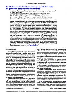
Fig. 2. The AirBurr prototype, with a collision-resistant carbon fibre cage and an integrated active uprighting mechanism to go back in take-off position when on the ground. (A) shows one half of the rollup mechanism used to close the legs for flight. (B) shows the end of the ’leg’ with attached ’feet’ for stability. (C) is the control electronics and on-board sensors.
A. Prototype Designing a flying robot that can navigate in cluttered environments and resist multiple collisions involves careful selection of robot morphology, materials and thrust generation. Though there are many types of flying robots (e.g. winged platforms, flapping-wing, airships) we choose a rotorbased design for its ability to hover, a necessary requirement in cluttered spaces. More specifically we use a coaxial-rotorbased design for its relatively small horizontal size, allowing it to fit through small entryways, though other configurations (such as 4- or 6-rotor designs) would also be suitable for indoor flight. Once a basic platform design is chosen, two additional considerations must be made for it to navigate cluttered environments: it must be robust to contact and capable of returning to the air after a collision. Robustness to contact can be accomplished through protection of sensitive moving parts, which in a hovering platform usually mean the propellers and control surfaces. In the case of the AirBurr we designed a protective structure around the entire robot using pulltruded carbon fibre rods and 3D-printed plastic interconnections. The structure remains flexible, able to absorb contact energy while protecting the rotors and control surfaces. An active recovery system was designed for the AirBurr robot based on 4 carbon fibre ’legs’ that are rolled up using a
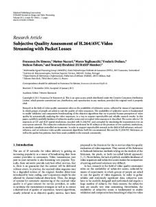
Fig. 3. (A) Setup with 6 optic-flow sensors and an IMU that will be miniaturized in the future for ego-motion estimation on the flying robot. A method using rate gyroscopes to automatically calibrate the viewing direction of such optic-flow sensors was developed and is described in [31]. (B) shows the calibrated orientations of each sensor.
DC motor and nylon string during flight. When the platform is on the ground and on its side the legs retract, providing an uprighting force that rotates the platform around its landing gear into an upright position, ready to take off again. Details surrounding the design of this mechanism can be found in [32]. Figure 2 shows the final prototype of the flying robot, along with details of its main components. The current prototype embarks a 3-axis MEMS accelerometer and a 3-axis MEMS rate gyroscope. The on-board processor (dsPic33) runs a Kalman filter to estimate the attitude of the platform, which is used to control the roll, pitch and yaw angles thanks to PID controllers. The attitude stabilization of the platform in hovering mode limits the lateral speed (or drift), which is a first step in the limitation of the kinetic energy. It is also key in the task of staying airborne when a disturbance happens, like a wind gust or contact with an obstacle. Finally, in a first step toward ego-motion estimation, a setup with six optic-flow sensors covering a wide field of view has been realized, and a method used to automatically calibrate the viewing direction of these sensors based on gyroscope readings is presented in [31] (see Figure 3).
Fig. 4. Test scenario, where the robot is flying in a cluttered environment (A). If a sudden collision with an obstacle happens (B), the robot falls on the ground, protected by the cage (C). It then uses its legs to upright (D) and takes of again in order to continue the mission (E).
B. Experiments The active self recovery mechanism was first tested multiple times by dropping the platform in several different orientations on the ground and activating the legs for the uprighting procedure. An example of an uprighting sequence is pictured in Figure 5. In order to demonstrate that our robot can achieve complete missions, the scenario of Figure 4 has been performed multiple times with the real platform. The attitude stabilization was achieved autonomously (see Figure 6), and the rest of the high-level commands (like angle or thrust setpoints and uprighting commands) were sent manually thanks to a remote control. The tests were very promising and proved that the robot can be controlled in flight, is robust to crashes once it collides with an obstacle, can recover from a fall to the ground and is able to take-off again. V. CONCLUSION This paper introduced the idea of flying robots that can recover from collisions, and the principle that autonomous indoor flight can also be tackled by intelligence in the mechanical design rather than only in the sensors and algorithms. New principles for sensing and control for such robots are introduced, as well as the idea that collisions can be exploited in order to navigate autonomously. Finally, a working prototype demonstrates the realization of a robot that can recover from collisions, opening the way to further advances in robust indoor flight.
Fig. 6. Example attitude stabilization in hover mode, where the pitch and roll angles and the yaw rate are automatically stabilized around zero.
R EFERENCES [1] J.-C. Zufferey, A. Beyeler, and D. Floreano, “Optic Flow to Steer and Avoid Collisions in 3D,” Flying Insects and Robots, pp. 73–86, 2009. [2] J. F. Roberts, T. S. Stirling, J.-c. Zufferey, and D. Floreano, “Quadrotor Using Minimal Sensing For Autonomous Indoor Flight,” in European Micro Air Vehicle Conference and Flight Competition (EMAV2007), no. September, 2007, pp. 17–21. [3] D. Schafroth, S. Bouabdallah, C. Bermes, and R. Siegwart, “From the Test Benches to the First Prototype of the muFly Micro Helicopter,”
Fig. 5.
[4]
[5]
[6]
[7]
[8]
[9]
[10]
[11]
[12]
[13]
[14]
[15] [16]
[17]
[18]
Self-recovery sequence, showing how the legs bring the platform from its side to a position ready for take-off.
Journal of Intelligent and Robotic Systems, vol. 54, no. 1-3, pp. 245–260, Jul. 2008. R. He, A. Bachrach, and N. Roy, “Efficient Planning under Uncertainty for a Target-Tracking Micro-Aerial Vehicle,” Distribution, pp. 1–8, 2010. S. Shen, N. Michael, and V. Kumar, “Autonomous multi-floor indoor navigation with a computationally constrained MAV,” in Robotics and Automation (ICRA), 2011 IEEE International Conference on. IEEE, 2011, pp. 20–25. M. Bl¨osch, S. Weiss, D. Scaramuzza, and R. Siegwart, “Vision based mav navigation in unknown and unstructured environments,” in Conference on Robotics, 2010, pp. 21–28. A. A. Faisal and T. Matheson, “Coordinated righting behaviour in locusts.” The Journal of experimental biology, vol. 204, no. Pt 4, pp. 637–48, Feb. 2001. L. Frantsevich and S. Gorb, “Structure and mechanics of the tarsal chain in the hornet, Vespa crabro (Hymenoptera: Vespidae): implications on the attachment mechanism.” Arthropod structure & development, vol. 33, no. 1, pp. 77–89, Jan. 2004. A. Hoover, E. Steltz, and R. Fearing, “RoACH: An autonomous 2.4 g crawling hexapod robot,” in Intelligent Robots and Systems, 2008. IROS 2008. IEEE/RSJ International Conference on. IEEE, 2008, pp. 26–33. N. O. P´erez-Arancibia, K. Y. Ma, K. C. Galloway, J. D. Greenberg, and R. J. Wood, “First controlled vertical flight of a biologically inspired microrobot.” Bioinspiration & biomimetics, vol. 6, no. 3, p. 036009, Sep. 2011. P. Fiorini and J. Burdick, “The development of hopping capabilities for small robots,” Autonomous Robots, vol. 14, no. 2, pp. 239–254, 2003. U. Scarfogliero, C. Stefanini, and P. Dario, “A bioinspired concept for high efficiency locomotion in micro robots: the jumping Robot Grillo,” in Proceedings 2006 IEEE International Conference on Robotics and Automation, 2006 (ICRA 2006). Ieee, 2006, pp. 4037–4042. S. Stoeter, P. Rybski, M. Gini, and N. Papanikolopoulos, “Autonomous stair-hopping with Scout robots,” in IEEE/RSJ International Conference on Intelligent Robots and System. Ieee, 2002, pp. 721–726. H. Tsukagoshi, M. Sasaki, A. Kitagawa, and T. Tanaka, “Design of a Higher Jumping Rescue Robot with the Optimized Pneumatic Drive,” in Proceedings of the 2005 IEEE International Conference on Robotics and Automation, no. April. Ieee, 2005, pp. 1276–1283. R. Armour, “A Biologically Inspired Jumping and Rolling Robot,” Ph.D. dissertation, University of Bath, 2010. M. Kovaˇc, M. Schlegel, J.-C. Zufferey, and D. Floreano, “A miniature jumping robot with self-recovery capabilities,” 2009 IEEE/RSJ International Conference on Intelligent Robots and Systems, pp. 583–588, Oct. 2009. M. Kovac, M. Schlegel, J.-C. Zufferey, and D. Floreano, “Steerable miniature jumping robot,” Autonomous Robots, vol. 28, no. 3, pp. 295–306, Dec. 2010. E. Beyer and M. Costello, “Measured and Simulated Motion of a
[19]
[20] [21]
[22] [23]
[24]
[25]
[26]
[27]
[28] [29] [30] [31] [32]
Hopping Rotochute,” Journal of Guidance, Control, and Dynamics, vol. 32, no. 5, pp. 1560–1569, Sep. 2009. A. Klaptocz, G. Boutinard-Rouelle, A. Briod, J.-C. Zufferey, and D. Floreano, “An indoor flying platform with collision robustness and self-recovery,” in 2010 IEEE International Conference on Robotics and Automation, 2010, pp. 3349–3354. J. Burdick and P. Fiorini, “Minimalist Jumping Robots for Celestial Exploration,” The International Journal of Robotics Research, vol. 22, no. 7-8, pp. 653–674, Jul. 2003. A. Kossett and N. Papanikolopoulos, “A Robust Miniature Robot Design for Land / Air Hybrid Locomotion,” in Proceedings 2011 IEEE International Conference on Robotics and Automation, 2011, pp. 4595– 4600. S. Zingg, D. Scaramuzza, S. Weiss, and R. Siegwart, “MAV Navigation through Indoor Corridors Using Optical Flow,” Flying Insects and Robots, pp. 3361–3368, 2010. F. Kendoul, I. Fantoni, and K. Nonami, “Optic flow-based vision system for autonomous 3D localization and control of small aerial vehicles,” Robotics and Autonomous Systems, vol. 57, pp. 591–602, 2009. B. Herisse, F.-X. Russotto, T. Hamel, and R. Mahony, “Hovering flight and vertical landing control of a VTOL Unmanned Aerial Vehicle using optical flow,” 2008 IEEE/RSJ International Conference on Intelligent Robots and Systems, pp. 801–806, Sep. 2008. S. Humbert, J. K. Conroy, C. W. Neely, and G. L. Barrows, “Wide-Field Integration Methods for Visuomotor Control,” in Flying Insects and Robots, D. Floreano, J.-C. Zufferey, M. V. Srinivasan, and C. Ellington, Eds. Springer Berlin Heidelberg, 2009, ch. 5. H. Dahmen, A. Millers, and H. A. Mallot, “Insect-Inspired Odometry by Optic Flow Recorded with Optical Mouse Chips,” in Flying Insects and Robots, D. Floreano, J.-C. Zufferey, M. V. Srinivasan, and C. Ellington, Eds. Berlin, Heidelberg: Springer, 2009. Y.-S. Chen, L.-G. Liou, Y.-P. Hung, and C.-S. Fuh, “Three-dimensional ego-motion estimation from motion fields observed with multiple cameras,” Pattern Recognition, vol. 34, no. 8, pp. 1573–1583, Aug. 2001. P.-J. Bristeau, F. Callou, D. Vissi`ere, and N. Petit, “The Navigation and Control technology inside the AR. Drone micro UAV,” in 18th IFAC World Congress, 2011, pp. 1477–1484. A. Bicchi, J. K. Salisbury, and D. L. Brock, “Contact Sensing from Force Measurements,” The International Journal of Robotics Research, vol. 12, pp. 249–262, 1993. S. P. Lacour, I. Graz, D. Cotton, S. Bauer, and S. Wagner, “Elastic components for prosthetic skin.” in 33rd Annual International Conference of the IEEE EMBS, vol. 2011, Aug. 2011, pp. 8373–6. A. Briod, J.-c. Zufferey, and D. Floreano, “Automatically calibrating the viewing direction of optic-flow sensors,” in International Conference on Robotics and Automation, 2012. A. Klaptocz, L. Daler, A. Briod, J.-C. Zufferey, and D. Floreano, “An Active Uprighting Mechanism for Flying Robots,” IEEE Transactions on Robotics, 2012.