[17] Levitz, C.L., Reilly, P.J., and Torg, J.S. âThe pathomechanics of chronic, recurrent cervical nerve root neurapraxia. The chronic burner syndrome,â Am. J.
Invited Paper
The application of 3D image processing to studies of the musculoskeletal system Bruce Elliot Hirsch*a, Jayaram K. Udupa b, Sorin Siegler c, Beth A. Winkelstein d a
Dept. of Neurobiology and Anatomy, Drexel University College of Medicine, 2900 Queen Lane, Philadelphia, PA, USA 19129 b Medical Image Processing Group, Dept. of Radiology, University of Pennsylvania School of Medicine, 4th Floor Blockley Hall, Philadelphia, PA, USA 19104 c Dept. of Mechanical Engineering and Mechanics, Drexel University, 32nd and Chestnut Streets, Philadelphia, PA, USA 19104 d Dept. of Bioengineering, University of Pennsylvania, 240 Skirkanich Hall, 210 S. 33rd St. Philadelphia, PA, USA 19104 ABSTRACT
Three dimensional renditions of anatomical structures are commonly used to improve visualization, surgical planning, and patient education. However, such 3D images also contain information which is not readily apparent, and which can be mined to elucidate, for example, such parameters as joint kinematics, spac ial relationships, and distortions o f those relationships with movement. Here we describe two series of exp eriments which demonstrate the functional application of 3D imaging. The first concerns the joints of the ankle complex, where the usual description of motions in the talocrural joint is shown to be incomplete, and where the roles of the anterior talofibular and calcaneofibular ligaments are clarified in ankle sprains. Also, the biomechanical effects of two common surgical procedures for repairing torn ligaments were examined. The second series of experiments explores changes in the anatomical relationships between nerve elements and the cervical vertebrae with changes in neck position. They provide preliminary evidence that morphological differences may exist between asymptoma tic subjects and patients with radiculopathy in certain positions, even when conventional imaging shows no difference. Keyw ords: 3D imaging, MR I, kinematics, ankle, subtalar joint, cervical spine, radiculopathy
1. INTRODUCTION 3D image processing has become quite common in med ical practice, with many sectional imaging devices now including the software needed to produc e such images. However, there is more information included in 3D data than simply pictorial renditions of the objec ts. For so me time we have b een using this information to study joint kinematics and the 3D relationships among organs. 1 In this paper we will summarize two areas where we have been applying image processing methods to improve our understanding of normal and abnormal anatomy and function, the ankle complex and the cervical spine.
2. THE ANKLE COMPLEX W e have p erform ed a numb er of experim ents using 3D reconstructio ns of the ankle and foot joints to study joint kinematics. From the surfaces created in the process we were able to measure a number of parame ters describing the morphology of the individual bones; their architecture, which is defined as the spatial relationship of one bone to another; and the changes in those architectural parameters as the joints go through their ranges of motion.2
*
Bruce.Hirsch@ DrexelM ed.edu; phone 1 215-991-8463, fax 1 215-843-9082
MIPPR 2009: Medical Imaging, Parallel Processing of Images, and Optimization Techniques, edited by Jianguo Liu, Kunio Doi, Aaron Fenster, S. C. Chan, Proc. of SPIE Vol. 7497, 74971B © 2009 SPIE · CCC code: 0277-786X/09/$18 · doi: 10.1117/12.851181 Proc. of SPIE Vol. 7497 74971B-1
The ankle comp lex includ es the an kle joint, which is the articulation between the tibia and fibula of the leg and the talus in the foot, and also the joints between the talus and the calcaneus. These latter bo nes articulate thro ugh posterio r facets forming the subtalar joint and anterior facets which are part of the talocalcaneonavicular joint; despite the fact that they are anatomically separate these two articular areas necessarily functio n together (Fig. 1). It is gen erally stated that the ankle is a hinge joint allowing only plantar flexion and dorsiflexion, while the oblique motions of pronation and supination occur largely at the joints between the talus and calcaneus. 3 However, there has been some indication that these oblique motions also occur at the ankle.4 Partly to resolve this question we created an MRI-compatible six degree of freedom device which allows known loads to be applied to the ankle complex. Using this ankle loading device (ALD) (Fig. 3) we applied either anterior drawer or inversion loads and measured the bones’ changes of position while a subject’s foot was imaged by MRI. 3D images were reconstructed using 3DVIEW NIX and various parameters of morphology, bony architecture, and motion were calculated.5
Figure 1. Bones and joints of the ankle complex
Figure 2. Ligaments of the ankle complex (modified from 9 )
This method of morphological and kinematic analysis had been shown to be highly reproducible in isolated bones and controlled m otions, 6 and a similar level of reproducibility also existed when the ALD was used for both in vivo studies of normal subjects and in vitro cadaver joints; the repro ducibility of morphological measurements of the foot bones was more than 96%.7 The difference in motion between the left and right feet was also small, less than 5.2%.7 Architectural parameters describing the relationships among the bones, such as distances between centroids and angles subtended at the centroids showed only slight differences between the neutral and stressed positions. 7 This was in agreement with previous data, although these architectural measurements in a small sample of pathological feet proved to b e different fro m those of no rmal fee t.8
Proc. of SPIE Vol. 7497 74971B-2
Perhaps most importantly, the results of this study confirmed that the ankle joint does not func tion only as a hinge joint. 4 Applying an inversion moment to the joint with the ALD led not only to plantar flexion at the talocrural joint, but also to adduction and inversion.7 (Ta ble 1) This is the mo tion kno wn as supinatio n. At the sam e time, the calcaneus inverted and adducted relative to the talus but there was very little plantar flexion. (Table 1) In all, about half the motion induced by inversion of the complex took place at the ankle rather than the talocalcanea l joints.7 A purely anterior drawer force produced its anterior translation at the talocrural joint, with very little at the talocalcaneal joints, but also small rotations at both jo ints.7 The ALD w as also used to study the mechanics of ankle inversion sprains and two common surgical procedures which are used to repair damaged ligaments in severe injuries. T here are a numbe r of ligam ents cro ssing these joints 9 but only two are com mon ly injured . In those sprains the mo st com mon ly injured ligament is the anterior talofibular (A TF L), which only affects the ankle joint. The next most commonly injured is the calcaneofibular ligament (CFL), but it is not affected unless the AT FL is damaged first.10 (Fig. 4) This latter ligament is placed so as to stabilize both parts o f the ankle com plex. In this study a cadaver mod el was used to mimic the soft tissue injuries of ankle sprains and their repair. Using the same procedure described to study normal joint kinema tics, intact specimens were imaged with M RI in neutral position and with inversion and anterior drawer loads. The AT FL was then sectioned, and the image sequences were repeated. T hen the CFL was cut, and the image sequences repeated again. The first of the surgical repairs studied, the Broström procedure, is an anatomical reconstruction which involves suturing the damaged parts of the torn ligaments to each other, sometimes with the reinforcement of adjacent tissues. A Broström repair was done to the cadaver ankle and the imaging sequences again were repeated. Finally, those sutures were removed and a Chrisman-Snoo k reco nstructio n, which thread s the peroneus brevis tendon along the path of the damaged anterior talofibular and calcaneofibular ligaments, was carried o ut followed ag ain by imaging.11
Figure 3. The Ankle Loading Device (ALD)
Table 1. Ro tations of the ankle joint complex and its components in response to a 3.4 Nm inversion moment in seven norm al subjects 7
Plantar flexion
Adduction
Inversion
Ankle joint
3.8± 6.5 /
2.8± 7.3 /
5.3± 7.0 /
Talocalcaneal joints
0.1± 3.1 /
1.7± 5.3 /
4.7± 4.6 /
Ankle complex
1.8± 5.1 /
6.5± 6.0 /
5.9± 7.5 /
Proc. of SPIE Vol. 7497 74971B-3
The results of intact joint motion verified those from the study of normal subjects, in that the supinatory motion of the ankle complex was divided between the ankle and talocalcaneal joints. 11 Additionally, it was shown that section of the ATFL alone produced negligible increased motion at either part of the ankle complex when an inversion force was applied.11 However, when the CFL was also cut there was a large increase in rotations at the ankle joint and a smaller increase at the talocalcaneal joints. In the experiments with the simulated surgical repa irs, both increased the stability of the joints but the Chrisman-Snook reduced the rotations under load more than the Broström procedure.11 (Table 2) Table 2. O verall motions in response to inversion and anterior drawer after cutting ankle ligaments and simulated surgical rep air 11
Inversion moment 3.4Nm
Anterior drawer force 150 N
Intact
18.0 ±6.8 /
11.2±3.1 mm
ATFL sectioned
20.0 ±7.1 /
12.8±4.1 mm
ATFL + C FL sectioned
28.6 ±11.3 /
14.1±4.1 mm
Broström
20.6 ±7.4 /
12.7±4.6 mm
Chrisman-Snook
16.5 ±6.6 /
13.3±4.8 mm
Also, in ten unembalmed cadavers we measured the distances between the attachment points of the two ligaments when they were cut, in the unstressed condition as well as in inversion and anterior drawer. There w ere no significant changes in the distances when the AT FL was cu t in either of the circumstances, which means that the remaining ligaments maintained the integrity of the joint. However, when the ATF L and CFL were both cut there was a significant increase in the distances between the attachment points of both ligaments in inversion (but not in anterior drawer). 12 This, and the expe riments measuring joint motion when the ATFL was sectioned,11 support and are consistent with the clinical practice of not repairing isolated AT FL tea rs surgically. 13
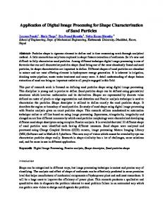
3. THE CERVICAL SPINE Cervical radiculopathy can result from any of a large number of causes, but it is not always clear from physical examination or imaging studies what is causing the nerve root compression in a given patient.14 However, given the extreme flexibility of the cervical spine and the transient loading from the head and torso,15, 16 it is not surprising that narrowing of the intervertebral foramina (neural foramina) has b een implicated in over 90 % o f radiculopathy cases. 17, 18 W e have hypothesized that in some of those cases where radiological indications of foraminal narrowing or other pressure on the nerve root cannot be seen, the dimensional changes are transient and dependent on the position of the neck at the time of imaging. The cervical spines of ten normal subjects and ten patients with radiculopathy (five of whom had radiologic evidence of nerve compression) have been examined with MR I. In order to have optimal quality in the images of the different tissues, the vertebrae were imaged with a sagittal T1 protocol and the neural structures with an axial proton density protocol. Normal subje cts were imaged three tim es: in neutral position, right rotation, and left rotation. Symptomatic patients were imaged twice: in the neutral position and in the po sition (right or left rotation) which elicited pain. The segmented bones, spinal cord, and nerve roots were registered and displayed as 3D o bjects (Fig. 4).19 Pain scores were recorded for all subje cts befo re and after imaging, and were significantly higher for the patient group. A numb er of 3D m easurements were made for each subject at each spinal level, including nerve root angle relative to the axis of the spinal cord, the length of the nerve root to the entrance of the intervertebral foramen, and the distance between the cord and the posterior surface of the vertebral body. Significant differences between the normal and p ain gro ups were co nsistently
Proc. of SPIE Vol. 7497 74971B-4
found at all levels in the distance from the cord to the vertebral body, and at isolated spinal levels for the other two param eters. 20 Further studies are underw ay to determine the relationship between architectural parameters of the cervical spine, spinal cord, and nerve roots and their relation to radicular pain.
Figure 4. A. Vertebrae C5-C7, spinal cord, and nerve roots from a normal subject. Left and center, two views with the vertebrae intact. Right, the vertebral bodies have been partially removed from display to show more of the nerve root relations. B. Enlargement of the spinal cord and nerve roots in MRI section.19 C. MR images in neutral position (left) and right torsion (right). The bone protocol is on top and the nerve protocol is on the bottom. 19
REFERENCES [1]
[2] [3] [4] [5]
[6] [7]
[8] [9]
Hirsch, B.E ., Udupa, J.K., G oncalves, R .J., and Roberts, D . “Kinematics of join ts of the foot via three-dimensional magnetic resonance images,” Proceedings of the First Conference on Visualization in Biomedical Computing, IEEE Comp uter Society, 232-237 (1990). Hirsch, B.E ., Udupa, J.K., and Stindel, E. “Tarsal joint kinematics via 3D imaging,” in: Udupa , J.K. and Herman, G.T ., eds. [3D Imaging in Med icine], 2nd Ed ., CRC Press, Boca R aton, FL, 329-359 (200 0). Standring, S. [Gray's Anatomy], Churchill Livingstone Elsevier, Philadelphia, 1442-14 46 (200 8). Siegler, S., Chen, J., and Schneck, C.D. “The three-dimensional kinematics and flexibility characteristics of the human ankle and subtalar joints - Part I: Kinematics,” J. Biomech. Eng. 110, 364-373 (1988). Udupa J.K., Samarasekera S., Goncalves R.J., Iyer K., Venugopal, K., and Furie, S. “3DVIEWNIX: An open, transportable, multidim ensional, multimod ality, multiparametric imaging software system,” Proc. SPIE 2164, 58-73 (1994). Udup a, J.K., Hirsch, B.E., Hillstrom, H.J., Bauer, G.R ., and K neeland, J.B . “Analysis of in vivo 3-D internal kinematics of the joints of the foot,” IEEE T rans. Biomed. Eng., 45(11), 1387 -1396 (199 8). Siegler, S., Ud upa, J.K., R ingleb, S.I., Imhauser, C.W ., Hirsch, B.E ., Odhner, D ., Saha, P.K ., Oke reke, E ., and Roach, N. “Mechanics of the ankle and subtalar joints re vealed through a 3 D q uasi-static stress M RI technique,” J. Biomech. 38, 567-578 (2005). Stinde l, E., Udup a, J.K ., Hirsch, B.E., and Odhner, D. “An in vivo analysis of the motion of the peri-talar joint complex based on M R imaging,” IEEE T rans. Biomed. Eng. 48, 236 -247 (2001 ). W ood Jone s, F. [Buchanan’s Manual of Anatomy], Baillière, Tindall and Cox, 665-667 , London, (1949 ).
Proc. of SPIE Vol. 7497 74971B-5
[10] Greenspan, A. [Orthopedic Radiology: A practical Approach], 2nd Ed., Lippincott-Raven, Philadelphia & New Y ork, 9.27-9.29 (1997 ). [11] Ringleb, S.I., Udup a, J.K ., Siegler, S., Imhauser, C.W ., Hirsch, B.E ., Liu, J., Odhne r, D., Okereke, E., and Roach, N. “The effect of ankle ligam ent damage and surgical reconstructio ns on the mechanics of the a nkle and sub talar joints revealed by three-dimensional stress MRI,” J. Orthop. Res., 23, 743-749, 2005. [12] Saldanha, V., Siegler, S., Hirsch, B.E., and Udupa, J.K. “Measurement of lateral ligament length under load using 3-D stress MRI,” J. Orthop. Sports Phys. Ther., 35, A-26 (2005). [13] Canale, S.T. [Campb ell's Operative Orthopaedics], Mo sby, St. Louis, 1086 (199 8). [14] Carrette, S. and Fehlings, M.G. “Cervical radiculopathy,” N. Engl. J. Med., 353, 39 2-399 (200 5). [15] Oliver, J. and Middleditch, A. [Functional Anatomy of the Spine], Butterworth Heinemann, Edinburgh, 17, 170-175 (1991). [16] Nuckley, D .J., Ko nod i, M.A ., Raynak, G.C., Ching, R.P., and Mirza, S.K.. “Neural space integrity of the lower cervical spine: Effect of normal range of motion,” Spine, 587, 587-595 (200 2). [17] Levitz, C.L., Reilly, P.J., and To rg, J.S. “The pathom echanics of chronic, recurrent cervical nerve root neurapraxia. The chronic burner syndrome,” Am. J. Sports Med, 25 , 73-76 (1997 ). [18] Muhle, C., Bischoff, L., W einert, D ., Lindner, V., Falliner, A., Maier, C., Ahn, J.M., Heller, M., and Resnick, D. “Exacerbated pain in cervical radiculopathy at axial rotation, flexion, extension, and coupled motions of the cervical spine: evaluation by kinematic magnetic resonance imaging,” Investigative Radiology, 35, 278-288 (1998). [19] W inkelstein, B.A., Udupa, J.K., Hilibrand, A.S., Schuster, J.M., Siegler, S., Hirsch, B.E., Borthakur, A., and Melhem, E.R., “Novel imaging approach using 3D stress MRI to detect altered biom echanics in patients with e voke d nec k pain,” presented at the Cervical Spine Research Society 36 th Annual Meeting (2008 ). [20] W inkelstein B.A., Udupa J.K., Hilibrand A.S., Schuster J.M ., Siegler S., Hirsch B .E., B orthakur A., Melhem E.R. “Novel Imaging Ap proach U sing 3D Stress M RI to Detect Altered B iome chanics in Neck Pain Patients,” presented at the BME S Annual Fall Meeting, Pittsburgh, PA, #OP 10-3-8D (20 09).
Proc. of SPIE Vol. 7497 74971B-6