G. Antchev, E. Cano, S. Chatelier, S. Cittolin, S. Erhan, D. Gigi, J. Gutleber, C. Jacobs,. F. Meijers, R. Nicolau, L. Orsini, L. Pollet, A. Racz, D. Samyn, N. Sinanis, ...
The CMS Event Builder Demonstrator based on Myrinet G. Antchev, E. Cano, S. Chatelier, S. Cittolin, S. Erhan, D. Gigi, J. Gutleber, C. Jacobs, F. Meijers, R. Nicolau, L. Orsini, L. Pollet, A. Racz, D. Samyn, N. Sinanis, P. Sphicas CERN, Div. EP, 1211 Geneva 23, Switzerland
Abstract The data acquisition system for the CMS experiment at the large hadron collider (LHC) will require a large and high performance event building network. Several switch technologies are currently being evaluated in order to compare different architectures for the event builder. One candidate is Myrinet. This paper describes the demonstrator which has been setup to study a small-scale (8x8) event builder based on a Myrinet switch. Measurements are presented on throughput, overhead and scaling for various traffic conditions. Results are shown on event building with a push architecture.
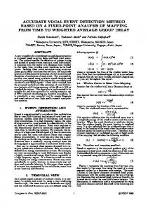
I. INTRODUCTION The architecture of the data acquisition (DAQ) system for the CMS experiment[1] at the future LHC pp collider at CERN is shown Fig.1. A large high performance network connects 512 readout units (RU’s), via a switch fabric, to 512 filter units (FU’s). The RU’s read out data from detector elements at a first level trigger rate of maximum 100 kHz and buffer the event fragments for up to 1 s. The expected average event size is 1 Mbyte, corresponding to event fragment sizes of 2 kbytes. With events of this size, the 512x512 event building network requires an effective aggregate bandwidth of 100 Gbyte/s. A software trigger running in the FU’s reduces the rate to about 100 Hz of events to record on permanent storage. The event manager broadcasts the first level trigger information to all RU’s and performs the event flow control from RU’s to FU’s. Trigger
Detector Frontend Readout Units
Event Manager
Event Building Network
transfer by requesting event fragments from each of the sources. The software trigger can be implemented in multiple levels and may use phased event building, where initially only a subset of the data corresponding to an event are moved and for the fraction of accepted events the additional event data are collected. This could reduce the required bandwidth for the event building network by 50% . Event building traffic is highly systematic as multiple sources compete for the same destination and, depending on the switching technology, the result may be reduced throughput, increased latency and/or loss of data. These effects can be minimised by an appropriate destination assignment algorithm and traffic shaping. Traffic shaping controls the traffic before submission to the network. One technique is the barrel shifter scheme. Here, sources are synchronised to emit fragments in time slots in such a way that no two sources send to the same destination during the same time slot and all sources regularly send to all destinations in a cycle. This is very efficient for fixed size fragments. Another technique is rate division, where the total link input bandwidth is equally divided between destinations. Before producing the design of the CMS DAQ system, small-scale prototypes (demonstrators) are being developed to evaluate technologies and study the functionality and performance of the various alternative designs. For event building, earlier work has been reported on Fibre Channel and ATM [2] and on simulations studies [3]. This paper reports on results obtained with a 8x8 Myrinet event builder. Myrinet is a cost-effective Gbit/s packet-switched network employing crossbars. The goal is twofold: the evaluation of the Myrinet technology and its applicability to event building traffic and also the study of generic event building architectures and protocols.
II. MYRINET Filter Units
Computing Services
Figure 1: The CMS data acquisition architecture.
A number of scenarios for event flow control have been proposed. In the push architecture, the event manager assigns a destination for each event and broadcasts the event identifier and destination to all sources. The sources then send their event fragments to the assigned destination. In the pull architecture, the destination processor initiates the data
Myrinet is a Gbit/s network composed of network interface cards (NICs), connected to crossbar switches by point-to-point links. It is used within concurrent and parallel supercomputers. Myrinet is specified at the data link and physical level as an ANSI standard[4]. Myrinet products are manufactured by Myricom[5].
A. Network Technology A Myrinet packet consists of a sequence of bytes starting with a routing header, followed by an arbitrary length payload and terminated by a trailer that includes a CRC byte computed on the entire packet. The routing header is used by
the switches, which strip these header bytes as they are used to steer the packet through the network. A Myrinet link is byte-wide and full duplex with a speed of 160 Mbyte/s in each direction. Communication is reliable –15 with very low bit error rates (below 10 ). Since the packet traffic does not share a single physical medium, a Myrinet network is, in principle, scalable. The non-blocking crossbar switches employ wormhole routing. The routing decision is made as soon as the packet header arrives, the stripped header is then sent to the chosen output link and the rest of the packet follows without being internally buffered. The packet header creates a temporary circuit (wormhole), which closes as the trailer passes through each device. Thus, a worm can stretch across many nodes and links at any time. Wormhole routing minimises latency and buffering requirements compared to switches using store and forward techniques. It also has the advantage that it allows arbitrary length packets. When the desired output port is not available, the worm is stalled and this information is propagated upstream using back-pressure flow control. This flow control is basically STOP/GO and utilises a small (46 byte) ‘slack’ buffer to absorb the reaction delay.
III. THE EVENT BUILDER DEMONSTRATOR A demonstrator has been set up to study a small-scale event builder based on Myrinet. All tests were done with a NxN topology, where the number of sources and destinations are equal (N), and N is set to 1, 4 or 8. The configuration of the demonstrator is shown in Fig. 3. A Myrinet switch (M2M-OCT-SW8) connects 8 sources and 8 destinations. The sources are Motorola MVME2306 VMEbus single board computers running VxWorks. The destinations are SUN Ultra5 PCI-based workstations running Solaris. The sources and destinations act as emulators of the readout units and filter units, respectively. These nodes are connected to the Myrinet network with 32bit/33MHz PMC and PCI interfaces (M2F-PMC32C, M2F-PCI32C), respectively. The function of the event manager is performed by an additional SUN workstation. The event flow control messages are transmitted over two separate 100 Mbit/s Ethernet switched networks, one connected to the sources and the other to the destinations. The software emulating the RU is derived from the full RU software currently under development [6]. 0
The performance of the network can be limited by headof-line blocking. When several packets are contending for the same output link and a packet is stalled because the required output link is busy, all packets in the input queue behind it are also stalled, even if their selected output link is free.
1
2
3
4
5
6
01 2 3
01 2 3
0
1
5
6
2
3
7
RU
B. Network Interface Card Figure 2 shows the block diagram of the Myrinet PCI network interface card. The interface is composed of a control processor called LANai with 1 Mbyte of SRAM. The SRAM serves as the network buffer memory and also as the code and data memory of the LANai processor. There are three DMA engines on the NIC: two for data transfers between the network and the SRAM, and one for moving data between the SRAM and the host main memory over the PCI bus.
EVM
4
0 M2F-PMC32C M2F-PCI32C
PCI 32 (33 MHz)
PCI Bridge
host DMA
RISC 33 MHz
Data 32 (66 MHz) Send DMA Recv DMA Pkt Interface
2
3
4
5
6
7
FU
Figure 3: Demonstrator layout with switch, RU sources, FU destinations and event manager (EVM). The internal switch structure shows the crossbar topology and numbering scheme. The bold line shows the path from source 5 to destination 2 via the intermediate crossbar switch 5 according to the algorithm IS = 4 + PN (see text).
Memory 1 MByte
Address LANai4
1
7
8
Myrinet SAN link
8 (80 MHz)
Figure 2: Block diagram of the Myrinet network interface card. The LANai processor executes a Myrinet control program (MCP) which supervises the operation of the DMA engines and implements a low-level communication protocol. The internal bus clock runs at twice the PCI clock allowing two DMA engines to operate concurrently at full speed.
The standard MCP software provided by Myricom did not provide the full functionality required for our application. Hence, a custom MCP and associated device drivers for the VxWorks and Solaris hosts have been developed implementing a low-level communication layer. This message-passing layer implements a circular buffer of message descriptors and associated data, both resident in the NIC memory. It provides reliable and in-order delivery with CRC error detection1. The DMA from host memory on the
1 In our tests no single CRC error was detected after more than 14 100 hours of running, corresponding to 10 bytes transmitted.
PCI bus to the NIC SRAM has been suppressed, because it would limit the overall performance due to limitations imposed by the available hosts2. Instead, the user header needed for the event building protocol is accessed by the host with programmed I/O and we suppress copying the event fragment user data are between NIC buffer memory and the host. This enables us to load the Myrinet switching network to the maximum possible extent. The M2M-OCT-SW8 is a composite switch with 32 external ports comprising eight 8-port crossbars. It is important to study a composite switch, since it is very likely, that the large switch fabric needed for CMS will have to be built by cascading smaller ones. A switch composed of smaller crossbars does not have the same behaviour as a switch consisting of a single larger crossbar, because of potential internal blocking. Figure 3 shows the internal switch structure and the way it is connected in our configuration. Although Myrinet links are full duplex, in the tests described below, the network is operated in one direction only. The routing of a packet through the 3-layer switch is fixed to a unique path for each source-destination pair. The algorithm used relates the intermediate switch number IS to the port number of the source switch PN (see Fig. 3) according to IS = 4 + PN Although alternate paths could have been used at run time, the motivation for a unique path is to avoid unintended randomisation.
Tests are made with both fixed and variable size event fragments. Variable size event fragments are generated to mimic the sizes expected for CMS readout. The sizes are generated according to the log-normal distribution for various parameter settings. As an example, Fig. 4 shows the frequency distribution for an average size of 2 kbytes and an RMS3 of 2 kbytes, which is believed to be approximate to CMS data taking. Note that the distribution is asymmetric, with the most probable value (about 1 kbyte) significantly different from the average value.
IV. RESULTS Results are presented on throughput measurements for various test configurations and traffic conditions. These are obtained by runs of typically 10 minutes, corresponding to a very large number of transfers. For each run, the total volume of data transmitted is measured at each source and destination.
A. Point -to-Point Traffic The basic performance of the NIC and switch was measured with a number of point-to-point tests. In these tests there is a fixed source-destination assignment, throughout the run. Test 1: A single source sends fixed size packets to a single destination through the switch. The measured throughput and corresponding rate are presented in Fig. 5. An asymptotic throughput of 132 Mbyte/s 4 is achieved and a 50 efficiency for a packet size of about 500 bytes.
�
140 120
LOG 1.0
240
Throughput
Rate 100
200
80
160
60
120
40
80
20
40
Rate [kHz]
Probability density (%)
0.15
Throughput (MByte/s)
LIN
280
0.1
0.1
0 0.0
0.1
1.0
10.0
0 100.0
Size [kByte]
0.01
0.05
Figure 5: Throughput and corresponding rate versus packet size for 1x1 configuration.
The transfer time of a packet calculated from the rate, is well described by the linear relationship: time = overhead + size / speed. 0.
2.
4.
0.
2.
4.
Size (kByte)
Figure 4: Fragment size distribution for variable size tests (linear and log scale) for parameter values set to average = 2 kbyte and RMS = 2 kbyte .
2 It has been verified, that on a PC platform the NIC can perform
DMA over PCI bus close to the PCI hardware limit.
�
A fit yields an overhead of about 4 s and a speed of 132 Mbyte/s. The overhead is attributed to processing time of the MCP in the NIC . The speed of 132 Mbyte/s is the hardware limit, determined by the NIC memory to link DMA (33 MHz, 32 bits). Note that the transfer time is not limited by the link
3 root mean square 4 1 Mbyte is defined as 106 bytes.
speed5 of 160 Mbyte/s. The throughput of this 1x1 configuration will be referred to as the full performance per source or destination, as it is not affected by traffic conditions.
respectively. Thus, the bandwidth sharing at the output is fair. It has been verified that the throughput of the other sources, i.e. the ones not sending to destination #0, remains unaffected.
Test 2: The scaling behaviour is studied for NxN configurations. Here, there are N concurrent transfers, with mutually exclusive paths, where source i sends to destination i (i=0..N-1). The aggregate throughput for a number of fragment sizes is shown in Fig. 6 for N=1,4,8. The throughput scales linearly with the size of the configuration (as expected given the mutually exclusive paths set up for this test).
For the 8x8 configuration, internal blocking occurs if sources connected to crossbar #0 share an intermediate path to the destination crossbar with sources connected to crossbar #1 (see Fig. 2). This can be provoked with the destination assignment s(01234567) d(01243567), where sources 3 and 4 are permuted and 0 0 and 4 3 contend for the crossbar 4 to 2 connection. The throughput at source #0 is reduced by a factor two and is equally shared6with source #4. The same holds for sources #3 and #7. It has been verified that the throughput of the remaining sources remains unaffected.
Aggregate Throughput (MByte/s)
1200
1000
512 1x1024 2x1024 32x1024
800
�
�
B. Random Traffic
600
400
200
0
1x1
4x4
8x8
NxN
Figure 6: Aggregate throughput for mutually exclusive transfers in NxN configurations versus N for fragment sizes of 512, 1024, 2x1024, 32x1024 bytes.
Test 3: The effect of output blocking and of internal blocking is examined. To this end, we measure the throughout at each source for various source destination assignments s(ijklmnop) d(i’j’k’l’m’n’o’p’), where source z sends to destination z’ (z=i..p). The case s(01234567) d(01234567) corresponds to test 2, discussed above. The throughput measured at source #0 is shown in Fig. 7 for various destination assignments.
�
�
�
140 120
Throughput [MByte/s]
�
100
d01234567 d00234567 d00034567 d00004567 d01243567
These tests are done without the event manager. Therefore, there is no external event flow control. It is interesting to investigate, whether the back-pressure flow control in Myrinet will bring the switch traffic in a stable equilibrium close to full performance. The RU sources generate event fragments of fixed size with event identifier evtid and send these to the FU destinations according to the round robin assignment Each event fragment is sent as a single packet. After initial broadcast of the start command, the sources are essentially running freely, only moderated by the back pressure mechanism. Two initial start conditions are tested; in the simultaneous start, all RU’s start sending fragments immediately after receiving the start command. In the retarded start, RU #n skips the first n events. This will start the traffic in the barrel shifter mode.
60 40 20
0.1
C. Event Building Traffic
FU# = evtid mod N .
80
0 0.0
The behaviour of the switch under random traffic has been measured with the same 8x8 configuration. Here, each source sends, independently, fixed-size packets to a randomly chosen destination. The measured throughput was about 60% of the full performance. This is because the throughput of the network under random traffic is limited by head-of-line blocking. An analytical model for this configuration gives 58% of the cross section bandwidth, which is in reasonable agreement with our measurement.
1.0
10.0
100.0
Size [kByte]
Figure 7: Throughput versus packet size at source #0 for various destination assignments in an 8x8 configuration.
Output blocking occurs if more than one source sends simultaneously to the same destination. An example of such a clash is the destination assignment s(01234567) d(00234567), d(00034567) and d(00004567). The observed throughput at source #0 is reduced with respect to s(01234567) d(012344567) by a factor 2, 3 and 4,
Results are shown in Fig. 8 and 9 for these two initial start conditions for the 4x4 and 8x8 configurations, respectively. The throughput versus fragment size is shown for FU #0. It has been verified that it is the same for all FU’s .
�
�
5 The packet interface inside the LANai processor inserts ‘IDLE’ control cycles onto the link if the next packet data byte is not available.
6 The observation that the throughput is constant down to about 500 bytes can be explained by the fact that both source and destination operate at 50% of the nominal rate and overhead from one source can be overlapped with transfer of the other.
140
Throughput [MByte/s]
120 100 80
simultaneous start retarded start
60 40 20 0 0.0
0.1
1.0
10.0
100.0
Size [kByte]
Measurements were done for the 8x8 configuration with fixed-size fragments. The throughput and event rate versus fragment size are shown for FU #0 in Fig. 10. Note that the rate of assembled events per destination scales as 1/N, because each destination receives 1 in N events, while the rate of event fragments is invariant. The achieved throughput is close to full performance, with a small degradation for small fragment sizes induced by additional event manager overhead. The rate of assembled events at a single destination (FU #0) is about 6.5 kHz for the nominal 2 kbyte fragment size. As there are 8 destinations, this corresponds to a level 1 trigger rate of about 50 kHz.
Figure 8: Throughput versus fragment size at FU destination #0 for event building traffic in the 4x4 configuration without event manager.
140
28
120
24
140
Throughput [MByte/s]
120 100 80
simultaneous start retarded start
60
100
20
Rate 80
16
60
12
40
8
20
4
Event Rate [kHz]
Throughput (MByte/s)
Throughput
40 0 0.0
20
0.1
1.0
10.0
0 100.0
Size [kByte] 0.1
1.0
10.0
100.0
Size [kByte]
Figure 9: Throughput versus fragment size at FU destination #0 for event building traffic in the 8x8 configuration without event manager.
The 4x4 configuration is equivalent to an actual 4x4 crossbar. Both initial start conditions give throughput close to full performance (Fig. 8). This is expected because after a few initial cycles the traffic evolves to a barrel shifter, irrespective of the initial condition. For the 8x8 configuration (Fig. 9), it can be seen that the retarded start locks the traffic into a mode close to full performance, whereas for the simultaneous start, it locks itself into a non-optimal mode. The latter is due to the internal blocking and depends on the destination assignment algorithm. A quantitative understanding of the non-optimal modes requires some further tests with different parameters and it will be interesting to compare these measurements with a detailed simulation.
D. Event Building with Event Manager Event flow control is implemented with the event manager in the following way. The event manager receives and collects event requests from the destinations, assigns the next event to a destination in a round robin fashion and broadcasts this information to all sources, which subsequently send the corresponding event fragments through the Myrinet network. For efficiency reasons, several requests are grouped in an Ethernet packet. The number of requests is always a multiple of the number of destinations N, up to a maximum of 352, imposed by the Ethernet packet length. The RU sources apply a kind of barrel shifter traffic shaping whereby RU #n starts with the n’th request in the packet and cycles through the list.
Figure 10: Throughput and rate versus fragment size at FU #0 for the 8x8 configuration with event manager. The rate is the number of events per second assembled at the single destination.
The effect of variable size event fragments has also been studied. Here, each source sends, independently, fragments with sizes generated according to a distribution mimicking that expected in the CMS readout (see section III). Measurements have been done for different combinations of average size and RMS of this distribution. Figure 12 shows the throughput versus average size for a number of different RMS values, compared to the fixed size case. 140 120
Throughput (MByte/s)
0 0.0
100 80
FIXED sz RMS=256 RMS=1024 RMS=2048 RMS=4096
60 40 20 0 0.0
0.1
1.0
10.0
100.0
Average Size [KByte]
Figure 11: Throughput versus average size for RMS values of 256, 1024, 2048 and 4096 bytes. The fixed size case is also plotted. Measurements are done at FU #0 for the 8x8 configuration with event manager.
The same measurements are shown in Fig. 12, where this time, the throughput is plotted versus the variable x=RMS/(average size) for a number of values for the average size. The case of fixed size correspond to the variable x=0 and
with increasing x, fluctuations increase. A considerable degradation of throughput with respect to fixed size is observed. This is due to head-of-line blocking. For the nominal average fragment size of 2 kbyte, the throughput reduces from 109 Mbytes/s for fixed size to 54 Mbyte/s for a RMS spread of 2 kbyte. 140
Throughput (MByte/s)
120
The development of the behavioural simulation of the Myrinet NIC and switches in the existing framework is in progress. The measurements obtained from the demonstrator provide the necessary parameters needed in order to make predictions for large-scale systems.
512 2x1024 4x1024 32x1024
100 80 60 40 20 0 0.0
0.2
0.5
0.8
1.0
1.2
1.5
Results have been presented on event building with a push architecture. For fragment sizes of 2 kbytes, the achieved trigger rate is about 50 kHz. As expected, substantial performance degradation occurs for event fragments of variable size. A possible mechanism to overcome this is the grouping of several event fragments into fixed-size packets. In principle, the present Myrinet hardware could satisfy the CMS requirements within a factor two, assuming scaling to a large (500 by 500) system.
1.8
2.0
RMS/Average
These studies are part of an ongoing program of work on the evaluation of event building architectures and switch technologies. They are expected to conclude in a first comprehensive design for the CMS DAQ in 2001, in time for the Technical Design Report.
Figure 12: Throughput for different combinations of average size and RMS plotted versus x=RMS/(average size) for average sizes of 512, 2*1024, 4*1024 and 32*1024 bytes. Measurements are done at FU #0 for the 8x8 configuration with event manager.
VII. REFERENCES
V. FUTURE WORK
[1] The CMS Collaboration, The Compact Muon Solenoid, CERN, Technical Proposal, No. 7, LHCC 94-38 December 1995.
The performance degradation for event fragments of variable size can be overcome by grouping several event fragments into large fixed-size packets and operating the system as a barrel shifter. An alternative could be a rate division algorithm, similar to the ATM constant bit rate mechanism. Here, event fragments are split into small size packets and the source cycles over all destinations. We will study the feasibility of such a scheme in the case of Myrinet. In the near future, the demonstrator will be expanded from a 8x8 to a 16x16 configuration, and the source and destination nodes will be gradually replaced by personal computers. Furthermore, we will introduce the new 64-bit based Myrinet NIC’s, which should allow to operate the network at the full link speed of 160 Mbyte/s. The same test bed will be used later to evaluate GigaBit Ethernet. So far, event building was studied with a push architecture. This will be extended to the pull scenario and also to phased event building.
VI. CONCLUSIONS The CMS event builder demonstrator based on Myrinet has been presented. The aim of the study is to evaluate the Myrinet technology itself and to examine event building architectures in general. The use of Myrinet as network technology enabled us to assemble a high performance test system in a short time. It also enabled us to assess the impact of overheads on overall performance. Throughput measurements were done on the 8x8 event builder for point-to-point, random and event building traffic. The composite switch behaves as expected. High efficiency can be achieved for large packets and appropriate traffic shaping, such as the barrel shifter.
[2] T.Ladzinski, A. Jusko, N. Lejeune, D. Samyn, CMS Data Links rd and Event Builder Studies, 3 Workshop on Electronics for LHC Experiments London, UK; 22-26 Sep 1997. Publ. In: Proceedings CERN, Geneva, 1997 CERB-LHCC-97-60 (450454). [3] N.J. Sinanis, et al., Performance Evaluation of the CMS DAQ System using Simulations, Computing in High Energy and Nuclear Physics Conference (CHEP98), Chicago Illinois, 1998. [4] ANSI/VITA 26-1998, Myrinet-on-VME protocol specification. [5] Myricom, Inc., Arcadia, CA, USA. http:://www.myri.com [6] G. Antchev et al., A Software Approach for Readout and Data Acquisition in CMS, This conference.