The DIVEBONE - An Application-Level for Internet-Based Emmanuel
Frbcon
Swedish
Institute of Computer Science Box 1263 SE-l 64 29 KISTA Sweden
-t4686331534
EmmanueLFrecon
@sics.se
M&ten
Chris Greenhalgh School of Computer Science and IT, University of Nottingham, Nottingham, NG7 2RD, UK +44 115 951 4221
[email protected]
Stenius
Swedish
Institute of Computer Science Box 1263 SE-164 29 KISTA Sweden +4686331540
[email protected]
While CVE platforms and applications are on the rise and starting to be used on a wider scale, there are still many technological issues that remain unsoIved. At the platform level, one of the main research challenges is to build a framework for controlling the large data flows that are generated by large-scale CVEs. The creators of multi-user virtual environments often wish them to be spatially extended (if not infinite), to contain many detailed and interactive objects and to allow many simultaneous participants to interact with each other and with the environment. However, this would not be possible without the use of specialised techniques.
ABSTRACT To allow the number of simultaneous participants and applications to grow, many Collaborative Virtual Environment (CVE) platforms are combining ideas such as loose consistency, absence of central servers and world sub-partitioning with IP multicasting. For long distance connections, most of these systems rely on the existence of the Internet multicast backbone - the MBone. However, its generality and complexity is often an obstacle to the establishment and testing of large-scale CVEs. This paper presents the DIVEBONE, an application-level network architecture built as a stand-alone part of the DAVEtoolkit [5]. The DIVEBONE is an application-level backbone that can interconnect sub-islands with multicast connectivity and/or single local networks. Furthermore, the DIVEBONE allows for visual analysis of the connection architecture and network traffic and for remote maintenance operations. The DIVEBONE capabilities have been demonstrated and successfully used in a series of large-scale panEuropean tests over the Internet, as well as in various experiments involving IP over ISDN and ATM. All trials have proven the qualitative and quantitative adequacy of the DIVEBONE in heterogeneous settings where multicast connectivity in other ways is limited.
This paper presents the DIVEBONE, an application-level network architecture built as a stand-alone part of the DNE toolkit (Distributed Interactive Virtual Environment) [5]. The DWEBONE is an application-level backbone that can interconnect sub-islands with multicast connectivity and/or single local networks. Furthermore, the DIVEBONE allows for visual analysis of the connection architecture and network traffic and for remote maintenance operations. In the next sections, we summarise some of the key aspects of the most well known CVE platforms to date and describe how a lack of adequate infrastructure for wide-area use impairs their development. We then detail how the DIVEBONE can augment the existing international multicast backbone and allow for a painless establishment of dedicated CVE overlay networks. In particular, we focus on the two main applications that compose the DIVEBONE software architecture. Finally, we summarise some of the main trials for which the existence of the DIVEBONE has played a crucial role. We quantitatively analyse a series of largescale pan-European trials over the Internet, performed within the European ACTS project COVEN and examine how the DDJEBONE have affected these trials.
Keywords CVE, VR, multi-user, Multicast, DIVE.
Network Architecture CVEs
MBone, Network Architecture,
1. INTRODUCTION During the past few years, many researchers have been using Virtual Reality (VR) together with network software to create Collaborative Virtual Environments (CVEs). They intend to help people who are geographically located at different places to work together. CVE applications are starting to become available to the public market. The practical applications of such systems include education, business, architecture, science, medicine, robotics, command and control, tools for the handicapped, simulators, distributed engineering, information retrieval, art, sports and fitness, and entertainment.
2. BACKGROUND
AND MOTIVATION
To allow the number of participants and applications to grow, many CVE platforms incorporate scaleable networking techniques. T’he recurrent theme of these solutions is that they utilise the general principles of occlusion and attenuation with (virtual) distance to reduce the number of participants that truly share a region of the environment. This is demonstrated by the use of regions in various platforms such as Massive [6], Spline [l], NPSNet [9] or the DIVE toolkit [5].
Permission to make digital or hard copies of all or part ol’this w[)rk fol or classroom use is granted without fee provided that topics
personal arc not
made or distributed for profit or commercial advantage ad that copies bear this notice and the full citation on the first page. ?‘o copy otherwise, to republish, to post on serxrs or to distribute to lists.
In order to minimise traffic within each region, the previously named platforms use one or several IP multicast groups for data, audio and video distribution. Through their implementation and experimenting, these platforms have shown that IP multicast is one of the keys to the success of large-scale and media-rich CVEs. Indeed, used in conjunction with techniques such as partial and
requires prior specific permission and/or B Ge.
VRST 99 London UK Copyright ACM 1999 I-581 13-141-0/99/12...$5.00
58
active replication of the shared environment, IP multicasting allows a system to minimise the amount of information that needs to be communicated during interactive simulations and ensures that network packets are only duplicated when needed.
.
Transparency - We wanted to achieve a network architecture as transparent as possible for the end user, ultimately making it “invisible”.
.
Easy set-up and maintenance - We wanted to allow regular users to build their own virtual CVE network across remote sites and to be able to intervene on an established architecture and modify its configuration on-the-fly as requirements change.
For long distance connections, most distributed VR platforms rely on the existence of the multicast backbone - MBone [8]. Our experience is that the MBone presents some weaknesses that hinder the establishment and testing of large-scale CVEs. .
Despite its wide acceptance within the research community, the MBone spreads slowly between sub-networks.
.
Although most operating systems now support multicast in their standard installation - sometimes as an option - some older versions do not or can not be upgraded.
.
At the corporate level, multicast support is still weak. Provided that the corporate local network is composed of relatively new operating systems it has an inherent support for multicast. However, a MBone connection (i.e. a multicast connection with the outer world) is often missing. Depending on the routers in use, multicast may also be restricted to individual LANs within the organisation.
.
3. AN INTRODUCTION
an experimental platform for the development of virtual environments, user interfaces and applications based on shared 3D synthetic environments. DIVE is especially tuned to multi-user applications, where several networked participants interact over the Internet. Started as a lab tool in 1991, DIVE has evolved into a well-developed system running on many platforms’. At the networking level, DIVE is based on a peer-to-peer approach, where peers communicate by reliable and non-reliable multicast based on IP multicast. Consistency and concurrency control of common data (objects) is achieved by active replication and reliable multicast protocols, based on ideas originating from Scaleable Reliable Multicast (SRM) [4]. Objects are replicated at several nodes, and these replicas are kept consistent by being continually updated. Update messages are sent by multicast so that all nodes perform the same sequence of updates. Typically, peers generating updates will apply these on their local replicas first, so as to ensure the fastest possible local interaction.
IP multicasting is not fully supported on different carriers such as ATM or ISDN lines.
Additionally, some of the concepts behind the MBone make it difficult to understand for novice users (and even for some expert users). Furthermore, any modification of the network parameters and configuration require the intervention of a system administrator. This is in strong opposition to the trial-and-error strategy that still characterises most CVE experiments.
DAVE supports live audio and video communication between participants. Sounds are spatialised according to the threedimensional position of their source, and video streams can be texture mapped on to objects in the virtual scene. In a typical DIVE world, a number of avatars (i.e. the representations of human users) leave and enter dynamically. Additionally, any number of applications can exist within a world. Such applications typically build their user interfaces by creating and introducing graphical objects into the virtual world. Thereafter, they “listen” to events in the world, so that when an event occurs the application can react according to some control logic. Events can be user interaction signals, timers, collisions, etc.
To tackle these obstacles, we envisaged an application architecture that would act as an extension to the regular MBone. Our goals are similar to the currently planned CBone (Cyberspace Backbone) [2], which also aims to serve as an application-driven replacement for the MBone, providing new services such as bandwidth reservation and dedicated multicasting. The existence of the CBone is bound to the emerging effort for a standardised network protocol for large-scale virtual environments: VRTP the Virtual Reality Transfer Protocol [3]. However, we have adopted a software dependent architecture that would help in validating the extension of the MBone for CVE purposes.
4. THE DIVEBONE ARCHITECTURE
Many multicast problems have their root in the generality of the MBone. Multimedia applications put strong real-time constraints on the networking layer. Furthermore, they differ significantly from one to the other. For example, one of the biggest challenges of audio conferencing over the Internet consists in providing a continuous audio stream based on a series of separate network packets. On the other hand, CVE platforms are more concerned with ensuring that the modifications applied at one site, together with the network packets that result, will be perceived by all other connected sites. We have developed an application-level network architecture, with the intention of treating network packets differently depending on their type in the near future. In the short term, the main goal of this architecture is to overcome the problems identified with the current MBone. Several key guidelines have driven our development: .
TO DIVE
DIVE, developed at the Swedish Institute of Computer Science, is
The key application program of the DIVEBONEis the so-called DIVE proxy server. This application provides two different services:
Architecture reuse - We wanted to build upon the existing MBone architecture, so as to benefit from its services and innovations.
.
The proxy server allows multicast unaware processes to join regular multicast sessions by acting as a message multiplexer for all connected applications. This is depicted in Figure 1 and detailed below. Here, knowledge of a specific proxy server is required when starting au application.
.
The proxy server allows MBone unaware networks to support multicast sessions by acting as a message multiplexer for all connected proxy servers. This is depicted in Figure 2
’ DIVE runs on many UNIX platforms and on Windows NT. Binaries are available for free for non-commercial use at http:/lwww.sics.seldivel.
59
t----
and detailed below. In this case, the existence of the proxy servers is invisible to the applications. ,----
rk v --APP, I ----
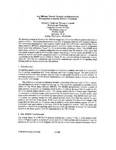
Figure 1: The proxy server as a simple message multiplexer. The proxy server can act as a simple message multiplexer for individual clients. It captures all DIVE multicast messages sent by applications and replicates the messages to all connected clients. Similarly, each time a client sends a message, the proxy server will replicate the message to all other connected clients and to the multicast group. As an example, in Figure 1, PS is a proxy server that will forward all data from App, to App, and the multicast network, and thus these messages will be received and interpreted by Appz, App3, and App4. Similarly, all messages sent by Appl will reach App,, App3 and App4. PS will also forward messages coming from the multicast channel, i.e. from App3 or App4, to APP~ and APPZ.
Figure 2: The DIVE multicast tunneller.
For simplicity, in the previous example we have considered that all the running DIVE applications had joined the same session, and thus were communicating through the same IP multicast channel. However, the DIVE proxy server is able to perform software, highlevel multiplexing among different groups.
5. ANALYSIS AND MAINTENANCE
:APP,,! I----
proxy
server
t- I -:AEPl,_:
as an application-level
To achieve transparent joining and leaving of multicast groups and thus allow applications along the DIVEBONE to communicate without knowledge of its existence, the proxy server listens to heart beat pings regularly sent by applications. These pings contain a list of joined multicast groups and inactive groups will be automatically left.
Another important part of the DIVEBONE allows for visual analysis of the connection instant network traffic. Additionally, this remote controller for the proxy server remote maintenance operations.
The proxy server can also act as a multicast tunnelling application. In addition to serving directly connected DIVE applications, proxy servers can also connect to one another in order to bind together MBone unaware multicast networks. Figure 2 depicts a complex example of five different proxy servers, named PS, to PS5, that allow communication between fourteen different applications, named Appl to App1.1.
is an application that architecture and of the application acts as a and enables run-time
The proxy server can log network traffic and a companion application visualises the statistics graphically in real-time. The application controls and receives data from the proxy server using socket communication. Consequently, it can be used to access and analyse remote parts of the DIVEBONE.
For simplicity, in this example we consider that all the running DIVE applications have joined the same session, and thus are communicating through the same multicast group. But, again, proxy servers are able to perform software, high-level multiplexing among different groups and serve different applications on different groups. Tunnelling proxy servers with one another constructs the DIVEBONE. Because of the probable complexity of setting up large DIVEBONE architectures, proxy servers are guarded against cycles. In short, packets entering the DIVEBONE are marked with the identifier of the proxy server that introduced them and proxy servers drop packets that are received from two different sources with the same identifier. The DIVEBONE uses principles that are similar to the first versions of the multicast routing daemon, i.e. DVMRP [ 111.
Figure 3. The companion application displays real-time graphical statistics of the instantaneous bandwidth used by the proxy server that it is connected to. A click on the Details button opens up the windows depicted in Figure 4. The application shows real-time graphical statistics of the bandwidth used by the different groups that are active within the proxy server. This is depicted in Figure 3. The most interesting statistics accumulate separate logs for each message type sent by DIVE applications, as shown in Figure 4. Using these statistics, it has been possible to optimise the most common operations and
60
established. In the end, a central proxy server run at the University of Nottingham and three proxy servers were tunnelled from Lancaster, London and Stockholm. All Dfvti applications involved in the trials, i.e. VR browsers and logging applications, ran using multicast. However, in some trials one person from SICS in Gothenburg connected his VR browser directly to the proxy server running in Stockholm.
detect flaws in the network algorithms, and thus improve scalability. Entity nsvsa9e Qbject Collfsion nor!% mgtato $rom 5tate cro%p Nell0 Entity
e&date
msractiotl Entfty
Signal
Flags
object TmiwPQlm Piowrty
Put
(Stockholm)
DivaNode Add Sub oJ&ct
Seal%
Figure 4. The companion application displays statistics at the buttons network packet level. Clicking on one of the Graph will open a window similar to the one depicted in Figure 3, but restricted to a given packet type.
Additionally, the companion application is also a remote controller for the proxy server that it is connected to. It can perform some maintenance operations on the DIYEBONE,without any need for application restart. Especially, it is able to connect or disconnect its proxy server to or from another running proxy server at run-time. Finally, as depicted in Figure 5, it can visualise the packet routing graph of the DIVEBONE,as seen from a proxy server. Graph detection is achieved by propagating a specific request that will result in propagation graphs being sent back by all leaf proxy servers. This allows a better understanding of the current configuration of the DIVEBONE.
Figure 6: The logical network architecture of proxy progressively established during the COVEN trials.
servers
For the trials, a murder mystery game, similar to Cluedo and called WhoDo was developed. The users at each site formed a team, and were associated with one of the suspects. Each team was then given a set of cards relating details about who committed the murder, where and with what weapon. Members of each team were then free to roam and question other people in order to try and ascertain the information relating to the murder (see Figure 7). The WhoDo gameplay favours collaboration and interaction.
Figure 5. The routing graph along the DIVEBONE, as seen from host with IP number 193.10.67.22.
6. PAN-EUROPEAN TRIALS Within the European ACTS project COVEN [lo], we have successfully used the DIVEBONE capabilities in a series of largescale pan-European tests over the Internet between spring and autumn 1998.
Figure 7: An overview of the WhoDo mansion.
6.1 Architectural Setting
In order to provide a basis for thorough analysis, a great deal of data was collected, including network packet headers (using the tcpdump tool), application events and additional position and orientation for the avatars.
These trials involved up to 20 active running processes(16 user and 4 agent processes) at five different sites. The logical networking architecture depicted in Figure 6 was progressively
61
sometimes using text channels in preference when responses are required.
6.2 Data Analysis In this section, we derive some general observations and insights from the last two WhoDo trials. These took place on a stabilised architecture and provided a consistent set of collected data from all sites. The ultimate question which we want to address is: .
.
Finally, there is a broader spread of speaking rates between 2 and 9%. We conjecture that this is a more “natural” level of audio participation in these meetings for most users.
But first, in order to address this question, we must consider the following issues:
To a first approximation, the audio network traffic is equivalent to that which might result from every participant ignoring every other participant and speaking at random! This strongly contradicts the common intuition (and sometime design heuristic) that people will take turns speaking.
.
6.2.2 DIVE Network Model
What are the costs and benefits, in terms of network of application-level multicast bridging as utilisation, exemplified by the DIVEBONE?
With regard to modelling user activity in CVEs: how much did people speak and move in these trials? This will allow us to define “average” levels of user activity, as they affect network requirements.
In this section we construct a simple model of the network traffic generated in a multi-user DIVE session. The network traffic generated by a DIVE session falls into five main categories:
.
What would we expect the network requirements for DIVE to be for varying numbers of users, i.e. determining a (preliminary) network requirements model for DIVE?
Initial state transfers, when applications join a new world and obtain the current world state from another process or from the WWW. This comprises one or more TCP flows.
.
What are the costs and benefits of a multicast-based platform (such as DIVE) compared to an unicast-based platform?
Multicast packets carrying real-time other processes, using UDP multicast.
The details of this analysis can be found in [7]. In the following sections, we summarise some of the most important results.
Multicast packets carrying new updates to the shared virtual environment state, e.g. the creation, movement, modification or removal of objects in the virtual world. These are also transported using UDP multicast.
6.2.1 User Activity Modelling In order to construct a model of DIVE network requirements we first need to characterise the activities of users, because this has a major impact on the traffic generated.
Multicast packets dedicated to ensuring reliability and liveness of multicast communication, also using UDP multicast and based on the SRM approach.
6.2.1.1 Movement
Encapsulated
We have found that the average fraction of the time which users spent moving was 26.3%. Around this average figure there is significant variability and the movement rates for individuals vary from 17% to 37%.
packets
being
passed between
For each of the first four categories, it is possible to use the user activity model sketched in the previous section and compare it to the actual data collected to provide an evaluation of the bandwidth requirements of each component. By combining them, we find a traffic model with the following distinct components: .
Per application unicast traffic: single TCP transfer per world, 5-1000 Kbytes per application per world-join.
.
Per application multicast traffic: audio, 7450 bits/second (92000 bits/second maximum); data updates, 4000 bits/second (30000 bits/second maximum); liveness, 900 bits/second; reliability, 800 bits/second (6000 bits/second maximum). Total, 13150 bits/second average, 128900 bits/second maximum.
.
Per world multicast traffic: 2400 bits/second.
6.2.1.2 Speaking DIVE (like many network audio tools) normally uses silence suppression to reduce the typical bandwidth utilisation for audio. Therefore, the presence of audio packets on the network from a particular host indicates that they are speaking.
If we assume that there are N simultaneous users and a single world then the multicast traffic is:
We have found that the average fraction of the time which a user spent speaking was 8.1%. There is a very broad spread of user speaking rates from 0.1% to 19.9%. In particular, the distribution appeared to be t&modal:
13 150x N + 2400 bits/second average 128900x N + 2400 bits/second maximum. If each user stays in a world for an average of T seconds and the world state size is S bits then the average bandwidth used for state transfer traffic is:
There is a cluster (4) of high speaking rates, around 20%. It appears that at least some of these very high rates correspond to users with particular experience or responsibility for the
NxS
t&k.
.
multicast
DIVEBONEproxies, carried using unicast UDP.
We also observe larger numbers of people moving at the same time than might be caused by chance. We believe that this arises where phases of the activity involve coordinated movement, or where movement of others prompts further movement (e.g. out of curiosity, or to follow the other). Observations of this kind show that caution must be used in attempting to share resources based on assumptions such as independence of users’ activities, and comparability of users.
.
audio from users or
There is also a cluster of extremely low speaking rates, around 1% or less. In previous trials, it has been observed that some users habitually avoid the audio channel,
bits/second
T For the example application in these trials S was approximately 4800 Kbits (the size of the WhoDo world) and T was
62
approximately 3600 seconds (each trial lasting one hour) giving an average bandwidth of:
message can be delivered to any number of hosts. Message. distribution is achieved by a combination of:
1333 x N bits/second long-term average
.
Combining this with the multicast traffic, above, we find that the expected bandwidth requirement for a DIVE session with N users is:
parallel reading on shared bus networks, e.g. Ethernet, Token ring; and
.
multi-destination fan-out of messages in multicast routers (and application-level router and bridge emulators as used in the DIVEBONE).
( 13 150 + 1333)N + 2400 bits/second average
With non-multicast communication (i.e. unicast) a copy of the message would have to be sent directly to every recipient. These copies would travel together over any common network links and subnets, increasing the total bandwidth requirements with blocks of highly correlated packets.
(128900+ 1333)N + 2400 bits/second maximum Average andpeak modelled bandwdth req”irsme”ts ,orDIVE.
From the previous section, the expected average bandwidth requirement for a DIVE session with N users was: B b
,e+m
t
1
/
/
(13 150 + 1333)N i- 2400 bits/second
J
If we assume that the only the N users then there will message. So, with only message must be sent N-l bandwidth requirement of:
applications present in the world are be (N-l) recipients for each multicast unicast networking, each multicast times, giving a new overall average
(13 1SO(N - l)+ 1333)N + 2400(/V - 1) bits/second Figure 9 shows how this compares to the multicast case from Figure 8. Figure 8: average and peak modelled bandwidth for DIVE.
requirements
Figure 8 plots (on a log-log scale) the predicted average and peak bandwidth versus number of users. The average and state transfer bandwidths are as calculated for the levels of user activity observed in the analysis, above. This shows the total unicast and multicast bandwidth assuming that application-level multicast bridging (such as the DIVEBONE) is not being used, and that reliability-related overheads are moderate and consistent. From the figure and equations we can observe that: .
Maximum bandwidths (ignoring state transfer transients) are about ten times average bandwidth figures. We may hope that with increasing numbers of participants the likelihood of them all being active simultaneously will be low enough to ignore; this may often be the case, but applications are likely to exist in which this is not.
.
Based on average bandwidths alone, a 10 Mbit/second Ethernet corresponds to 760 concurrent users; based on maximum bandwidths this falls to 77. Even with maximum bandwidth figures the number of users is large enough that we might expect reasonable statistical behaviour, allowing significantly more concurrent users.
Figure 9: average modelled bandwidth requirements assuming multicast or unicast communication.
for DIVE,
6.2.4 Eflects of the DIVEBONE The COVEN trials have used a star topology of DIVEBONE proxies, as depicted in Figure 6. Each of the outlying sites connected to the hub via a per-site DIVEBONE proxy.
Based on the authors’ experiences it is extremely likely that the host performance will become the limiting factor long before these levels of simultaneous users are reached.
Ignoring inter-site packet loss, each site will see exactly the same multicast traffic. Some of it originates from local machines while the remainder has to be forwarded onto the local network by the local DIVEBONE proxy.
6.2.3 Multicast vs. L&cast Communication
In addition, each leaf (non-hub) site will have one unicast flow connected it to the hub DIVEBONE confirmed by our data collection, the total requirements for this flow (in both directions) will
As we have seen, the dominant communication mode for DIVE is peer to peer multicasting (based on IP multicasting). This provides network communication semantics in which a single
63
DIVEBONE proxy. As bandwidth be almost
exactly the same as the total local multicast traffic. This is because: . every multicast packet on the local network which originated from a local machine will be forwarded by the DIVEBONE proxy (as a unicast packet) to the hub; and . every multicast packet on the local network which originated from a remote machine must have got here by being sent to the Iocal DIVEBONEproxy (as a unicast message)from the hub. From this it should be clear that each leaf network of the D~VEBONEwill observe as much additional unicast inter-site traffic as there is DIVE multicast traffic on the local network. In the worst casethis would double the total bandwidth utilisation on the local network. We can generalise this observation to include the hub network and non-star topologies: if P is the number of D~VEBONEconnections to a network, then a network will send or receive P times as much additional inter-site unicast traffic as there is multicast traffic in the session. For example, the hub site in these trials supported three DIVEBONEconnections, one to each of the other three sites. In a more general tree topology each node in the DIVEBONEtree (excepting the root node) has one more connection than it has children (since it also has a connection to its parent node). If we apply this to the simple DIVE bandwidth model developed previously, then for a site with P DIVEBONE connections the new total bandwidth on the local network will be approximately: (13150(P+l)+1333)N+1333M
+24OO(P+l)
Figure 10 shows the characteristics of this model for values of P from zero (no DIVEBONE) to three. The unicast equivalent bandwidth calculated previously is also shown for comparison. Provided the total number of users exceeds the number of sites then the use of the DIVEBONEis no worse than unicast peer-topeer communication. As the number of users increases for the same number of DIVEBONE connections then the bandwidthrelated benefits of multicasting are reasserted.
7. TRIALS
ON ALTERNATE
CARRIERS
Whereas the COVEN trials described above have been performed over the Internet, the DIVEBONE toolkit has proven useful with other network carriers as well, such as ATM and ISDN. Specific limitations and problems encountered when running IP traffic over these carriers were overcome using of different proxy server configurations.
7.1 National ATM infrastructure DIVE has been used in a variety of application demonstrations and experiments over the VITI network [12], an ATM network in Sweden that interconnects several academic nodes over the country. During these trials, IP was used over the ATM network, including multicast. However, since the setups at the different sites involved in the trials varied, it was difficult to achieve a “regular” purely multicast-based DIVE session just by re-routing all multicast traffic to the ATM network. For instance, at one site the machine used to run DIVE was not directly connected to the ATM network and multicast traffic could not be cleanly and easily re-routed. In addition, all of the involved nodes were simultaneously connected to the Internet, which further complicated the process of ensuring that DIVE traffic was routed over ATM. To address this problem, the DIVEBONEtools were successfully used. By using a setup involving a proxy server at one of the sites, to which the other nodes could connect explicitly, the DIVE traffic was explicitly sent over the ATM network. The above-mentioned solution, however, meant that the multicasting of the ATM network itself was not used. To remedy this, an alternative solution could be -to employ proxy servers running on the machines directly connected to ATM, and let any local DIVE processes connect to them. By doing so, the local connections to the proxy servers would be one-to-one, but the traffic over the ATM network could be a multicast session involving the directly connected proxy servers and DIVE clients.
bits/seconds
This is not quite correct, since it fails to take into account the distribution of unicast state transfer between DIVEBONEsites. Specifically, the initial state transfer to a process at another DIVEBONE site will not be seen locally unless that state is transferred from a local process. As the number of DIVEBONEsites in the network increases this becomes less and less likely. This would reduce the effect of the 1333 terms in the above expression, although we will ignore this effect for the purposes of this simplified analysis. ““Imat----. 231DwEBoneconnectiono DNEBoneconnections ...... DI”EBonecon”ections ---NoDIVEBone connecbons -.-
7.2 Point-to-point
connections using ISDN
Similarly to the ATM-based experiments described above, ISDN has been used as a carrier for IP traffic during several DIVE demonstrations and trials where IP connectivity has otherwise been limited. In these cases,however, multicast traffic could not be routed over the ISDN line, which meant that any direct connection between different DIVE peers had to be tunneled somehow. The DIVEBONEwas a natural tool to use for this type of traffic tunneling: By setting up a proxy server at one end of the line, any DIVE client on the other end could connect directly using regular TCP or UDP connections. Alternatively, a multicast tunneling setup with one proxy server at each end of the ISDN line, each
Figure 10: modelled DIVE traffic with varying numbers of DIVEBONE
connections.
64
connected to the other, could be used to provide a more transparent link between the sites.
8. CONCLUSION
AND FUTURE
10. REFERENCES [II
Barrus, J., Waters, R. and Anderson, D. Locales: Supporting Large Multiuser Virtual Environments, IEEE Computer Graphics & Applications, Vol. 16, No. 6, 1996, 50-57.
PI
Brutzman, D., Zyda, M. and Macedonia, M. Cyberspace Backbone (CBone) Design Rationale, in Proceedings of 15th DIS Workshop on Standards for the Interoperability of Distributed Simulations, Institute for Simulation and Training (Orlando FL, 1996).
WORK
The DIVEBONEmay be regarded as a hybrid multicast/unicast communication infrastructure. For many users per site it retains the benefits of native multicasting. At the expense of some unicast traffic it allows a number of distributed sites to be connected relatively easily and reliably and without requiring accessto the normal MBone. In its current form it may be argued that the DIVEBONEis an interim solution to wide-area multicasting; it is hoped that general-purpose solutions to these problems will become widespread over the next five years or so. However, beyond the bridging role that it currently plays there remain a number of additional roles for application-specific wide-area bridges/routers such as this, which could not be addressedby generic multicast routers. Specifically, there is scope to perform application-specific manipulation on the wide area traffic.
[31 Brutzman, D., Zyda, M., Watsen, K. and Macedonia, M.
Virtual Reality Transfer Protocol (VRTP) Design Rationale, in Proceedings of Workshop on Enabling Technology: Infrastructure for Collaborative Enterprises (WET ICE): Sharing a Distributed Virtual Reality (Cambridge MA: MIT, 1997). I41 Floyd, S., Jacobson, V., McCanne, S., Liu, C.-G. and Zhang
L. A Reliable Multicast Framework for Light-Weight Sessions and Application Level Framing, in Proceedings of ACM SIGCOMM 95 (New York, ACM Press, 1995), 242256.
Indeed, in its current form, the DIVE proxy server is not aware of the worlds within which the different applications interact. It simply acts as a message dispatcher at the multicast level. However, a clear evolutionary step is to build intelligence into the proxy server and use it to compress and pre-format data before sending it to its direct clients, allowing them to run on lowbandwidth networks such as modem lines. Examples of preformatting include audio spatialisation and mixing. Another is to automatically duplicate the proxy servers in order to cope with the additional computational and network load introduced by new clients. Computational load is likely to increase if compression and pre-formatting are introduced. Yet another example consists in compression or abstraction of wide-area data.
applications. COVEN deliverable 3.6, October 1998. WI Kumar, V. MBone: Interactive Multimedia On The Internet (Macmillan Publishing), 1995, ISBN l-56205-397-3.
9. ACKNOWLEDGMENTS
PI Macedonia, M., Zyda, M., Pratt, D., Brutzman, D. and
[51 F&on, E., and Stenius, M. DIVE: A scaleable network architecture for distributed virtual environments, Distributed SystemsEngineering Journal, Vol. 5, No, 3, 1998,9 1-100. [61 Greenhalgh, C. Large Scale Collaborative Virtual Environments, to be published spring 1999, London, Springer-Verlag. [71 Greenhalgh, C. (ed.). Network assessment of the on-line
Barham, P. Exploiting Reality with Multicast Groups: A Network Architecture for Large-scale Virtual Environments, in Proceedings of IEEE Computer Graphics & Applications (1995), 38-45. [lo] Norrnand, V. et al. The COVEN Project: Exploring Applicative, Technical and Usage Dimensions of Collaborative Virtual Environment, Presence: Teleoperators and Virtual Environments, 8(2), in press. [ 1l] Pusateri, T. Distance Vector Multicast Routing Protocol, 1997, IETF - Work in Progress draft-ietf-idmr-dvmrp-v3-05.
This research was partly funded by the European ACTS programme (COVEN AC040). We would like to thank all people at Lancaster, Nottingham, SICS and UCL that participated to the trial effort and allowed us to gather many interesting results. The majority of the national ATM trials were done within the DING pre-study, funded by the Swedish National Board for Industrial and Technical Development (NUTEK). Finally, many thanks go to Olof Hagsand, at SICS, for the first basic implementation of the proxy server, and to Anthony Steed, at UCL, for the implementation of the WhoDo application.
[ 121The VITI Network, http://www.siti.se/viti/
65