We have equipped all surgical instruments for our setup ... setting as shown in Fig. 4, center. We call the coordinate system spanned by the axes xV , yV and zV ...
The Endo[PA]R System for Minimally Invasive Robotic Surgery Hermann Mayer, Istv´an Nagy, Alois Knoll
Eva U. Schirmbeck, Robert Bauernschmitt
Robotics and Embedded Systems Technische Universit¨at M¨unchen Garching, Germany Email: {mayerh,nagy,knoll}@in.tum.de
Klinik f¨ur Herz- und Gef¨asschirurgie Deutsches Herzzentrum M¨unchen M¨unchen, Germany Email: {schirmbeck, bauernschmitt}@dhm.mhn.de
Abstract— Minimally invasive robotic surgery systems has entered daily practice in dedicated clinical centers. Especially heart surgery profits from this new technique, due to a higher accuracy compared to conventional endoscopic interventions. Nevertheless some drawbacks have restricted a broader acceptance of these devices. The most urgent issues are lack of haptic feedback and prolonged operation time. Our research project tackles both topics, on the one hand by adding high fidelity force-feedback, on the other hand by automating recurrent manipulation tasks. These features have been integrated into the Endo[PA]R (Endoscopic PartiallyAutonomous Robot) system, an open evaluation platform for robotic surgery. The setup comprises two low-payload robots equipped with sensorized surgical instruments and a third robot carrying a stereo camera system. Trocar kinematics, enabling surgical manipulation through small incisions, has been implemented for all robotic arms. In order to ensure operation close to reality, a thorax and heart phantom for surgical training was used in the experiments. Stereo vision is provided via a head-mounted display and force-reflective input devices are employed for user interaction. The system was evaluated by surgeons and it was capable of performing autonomous knot-tying.
I. I NTRODUCTION Minimally invasive surgery (MIS) has become a common procedure during the last decades. It features some outstanding advantages compared to open surgery. Patients profit from significantly reduced tissue trauma and shorter recovery times, since major incisions are avoided. On the other hand MIS is a challenge for every surgeon, due to reduced sight and manipulability. Therefore robot assisted, teleoperated systems were proposed to eliminate these limitations. Newly designed instruments have returned fully dexterous manipulation inside the body by preserving the same degrees of freedom like the human hand (e.g. daVinci [1], ZEUS [2]). Both mentioned systems are commercially distributed and many delicate operations have already been performed with them ([3], [4], [5], [6]). Nonetheless many surgeons are missing tactile- and force-feedback, which is a crucial factor for most surgical tasks [7]. Haptic feedback is indispensable for both, subtle handling of suture material (knot-tying) and inspecting the constitution of manipulated tissue. Extended operation times are also typical phenomenons of existing systems. This disadvantage most likely results from missing forcefeedback and reduced sight. Our approach to overcome these limitations is provision of haptic feedback and partial
autonomy. The latter should accelerate recurrent tasks and is independent from visual information. Our aim is to provide the surgeon with an operation environment very similar to manual instrumental surgery (i.e. the surgeon can always feel forces exerted on the instruments). According to [8], the influence of force feedback on operation time seems to be even more important than it is for visual feedback. Following this analysis of deficiencies, we developed an open evaluation platform for robotic surgery that was tailored to the needs of sensitive force feedback for delicate operations like bypass operations in cardiac surgery (Fig. 1). Our workstation is not a telemanipulator that is controlled by visual servoing of the surgeon. Instead, it can be directly controlled by transmitting 6 DOF coordinates to its control unit. This is an important feature for closing control loops in machine learning applications, which can be applied in order to autonomously perform certain recurrent tasks, e.g. automated cutting or knot-tying.
Fig. 1.
Operation Snapshot
The goal of our prototypical system is three-fold: (i) implementing full Cartesian control of the combination of robot and articulated instrument along with software facil-
ities for realistic simulation, (ii) meeting all the requirements for sensitive force feedback enabling complex and complicated surgical procedures like knot-tying, and (iii) providing an open experimental platform for researchers that have no access to proprietary software interfaces of the other systems. II. P REVIOUS W ORK Since the interesting field of robotic surgery has attracted many researchers, there is a variety of systems with different features implemented by other groups. At the University of California, Berkeley, a robotic system was developed, which has already been used to perform certain surgical tasks like suturing and knot-tying ([9]). The Korean Advanced Institute of Science and Technology has developed a micro-telerobot system that also provides force feedback ([10]). In Germany two systems for robotic surgery were built at the Research Facility in Karlsruhe ([11]) and at the DLR in Oberpfaffenhofen ([12]). While the first system provides no force feedback, the latter system is equipped with PHANToM devices for haptic display. There is also some work available dealing with analysis of knot-tying. At Johns Hopkins University, Kitagawa et al. [13] have evaluated occurring forces during knot-tying. They did not measure forces directly at the instruments and during realistic operations, but with a specially designed measurement contrivance. Cao et al. [14] have analyzed a variety of surgical tasks (among other things knot tying) and decomposed them into subtasks. They did not include force measurement.
end of the shaft can be rotated and adaptation of pitch and yaw angles is possible. All movable parts of the gripper are driven by steel wires. Their motion is controlled by four driving wheels at the proximal end of the instrument, one for each degree of freedom (two for yaw of the fingers). In order to control the instrument, we have flanged servos to each driving wheel by means of an Oldham coupling. This guarantees instrument movement free of jerk. The servo controllers are connected via serial lines to a multi-port interface card. Since the rotation of the robot’s flange and the rotation of the instrument share one axis, the combination of robot and instrument results in a manipulator with eight degrees of freedom. That means our system is a redundant manipulator. This can be exploited to evaluate different kinematical behaviors. To address the aspect of intuitive operability of the user interface, we apply the concept of so-called trocar kinematics: the manipulator has to pass through a fixed hole (“port”) in the patient’s chest. This restricts the degrees of freedom of the instrument (Fig. 2). We have equipped all surgical instruments for our setup with strain gauge sensors. They are applied by means of adhesive sealing and heat shrink tubing. Strain gauge technique is well-approved in other areas (like crash testing) and provides solutions for multifarious requirements (like high temperature, moisture and corrosive environments). Raw signals acquired from the gauges are preprocessed with high-precision amplifiers. They are finally transferred to the control computer by means of a DeviceNet bus. For user input and force reflection we employ two PHANToM devices. Those are available in different versions with different capabilities. Our version provides a full 6 dof input, while force feedback is restricted to three translational directions. The user controls a stylus pen that is equipped with a switch that can be used to open and close the microgrippers. An endoscopic stereo camera system delivers 3D impression of the scene to a binocular head-mounted display.
�
Location of the Instrument and Camera Port
��
Fig. 2.
� �� �� �� � �� � �
�� � �� ��� ��
�� �
��
IV. I NVERSE K INEMATICS
�
��
� �� �� ��
��
�
Our setup comprises an operator-side master console for in-output and a patient-side robotic manipulator that directly interacts with the operating environment. As shown in Fig. 1, our system has two manipulators, which are controlled by two input devices, a third robot is carrying an endoscopic stereo camera system. The motor part of our system consists mainly of two major parts: A low payload robot that carries an adapter for flanging the instruments. This contrivance can accept different exchangeable surgical instruments, which are deployed with the surgical workstation daVinci (TM). The surgical instruments have three degrees of freedom. A micro-gripper at the distal
��
III. M ATERIALS AND M ETHODS
Fig. 3.
Schematic System Overview
As mentionend above, trocar kinematics restricts the
manipulability of the instrument. Feed (translation) and rotation axes must always intersect with the fixed port. Given the position and rotation of the end effector, we have to calculate all joint angles of our eight degrees of freedom (DOF) system. The resulting angles can be directly applied to the robotic system – or they can first be evaluated in a simulation environment. Because the system’s working space is mostly determined by the working space of the robots, we have chosen their base coordinate system K as our base system. In our setup, the surgeon (handling two haptic input devices of type PHANToM) and the observation camera, respectively, are placed in front of the robots: the xK -axis points in the direction of the user, while the zK -axis points upward to the ceiling (Fig. 3). The force-feedback styluses are placed in front of the user and, therefore, the zP -axis is collinear with the xK -axis of the robot system. The yP -axis points up to the ceiling, while the xP -axis points to the right hand side (Fig. 3).
V. S IMULATION In order to check certain operation sequences (e.g. the complicated procedure of knot-tying) before applying them to the real world, we have developed a realistic simulation of our system. Since the model has the same geometry as the real system, all joint angles obtained from the inverse kinematics can be directly applied to it. The model is displayed in an Open Inventor-GUI. Input data can be recorded to a data base for subsequent use with the simulation or the real system. This simulation was especially useful to detect some unusual motion sequences that could lead to failures of the real system. For example, the robot tends to move too fast if the instrument tips approach come too close to the port. The simulation can also be used in parallel with real manipulations. This can be very helpful if the remote user has no full sight of the operation environment (e.g. if instruments are occluded by other objects).
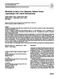
The specification of the coordinate system for the minimally invasive instrument is crucial for all further considerations. As mentioned above, we want to make the control of the instrument appear to the surgeon as “natural” or “intuitive”. We therefore modelled the kinematic structure on the observation of the human hand: if humans perform very precise manual tasks (e.g. a surgeon making a cut), we turn the hand about a rotation center that lies near the first link of the fingers (Fig. 4, left). If we want to mimic this behavior in our instrument control – while preserving mechanical feasibility – then a good compromise is a setting as shown in Fig. 4, center. We call the coordinate system spanned by the axes xV , yV and zV the virtual instrument system. The mechanical rotation axes of the real instrument are named xM , yM and zM (Fig. 4, right). Fig. 5.
]
[
[
�
[
]
�
]
\
�
\
Fig. 4.
\
Virtual Instrument Definition
The inverse kinematics of the system consists of two parts. First, the intended posture of the virtual instrument system has to be mapped to real axes. This uniquely determines the orientation of the intrument’s shaft, which is mounted to the flange of the robot. Therefore the second part is extracting the joint angles of the robot from the homogeneous transform matrix of the flange. For a detailed derivation of the inverse trocar kinematics of the system refer to [15]. In addition all measured forces are referenced with the coordinate system of the input devices.
Screenshot of the Simulation Environment
Fig. 5 shows the simulation environment including a CT-scan of the thorax and heart phantom. A detailed closeup view of the operation situs is depicted in the lower right corner of the simulation window. The exact model allows for an appropriate instantiation of previously acquired tasks, since transformation parameters (translation, rotation, scaling) can be extracted from simulation. A possible scenario is automatically completing a knot: as an occurrence of an already recorded manipulation sequence is recognized, a context-sensitive instance of that sequence is replayed. Before the task is actually completed by the robotic system, a virtual execution is displayed to the surgeon, who can choose between either discarding or performing the task. VI. E VALUATION OF F ORCE F EEDBACK With the help of this setup we have performed different tasks known from surgical practice and evaluated the impact of force measurement. Our hope is, that haptic feedback contributes to a better performance of systems for robotic surgery by preventing force-induced damages.
Examples for such harms are breaking of thread material, ripping tissue and strangulate sutures.
(1 ms) the instant recognition of such suture breaks is possible, preventing the robotic system from unexpected behavior.
Force Progression
B. Preventing Suture Material Damage
2 1.5 1 0.5
Force[N]
0 -0.5 -1 -1.5 -2 -2.5 Left Fx Left Fy Right Fx Right Fy
-3 -3.5
5000
10000
Fig. 6.
15000
20000 25000 Time[ms]
30000
35000
40000
Winding a thread to make loops
The tensile strength of absorbable and non-absorbable sutures is critical, both during and after surgical procedures. Breaking strength can be measured using either a ”straight pull” test or a ”knot pull” test. Having the breaking strengths of all used sutures enables us to prevent suture material damage by limiting the applicable forces to adequate maximal values. Fig. 8 shows the progression of forces while trying to break original surgical suture material, in this case Ethicon PROLENE (7/0, Polypropylen, not absorbable). Fig. 9 shows breaking the thread (PROLENE 7/0) while tying a knot. As expected, the thread was broken at the knot position by significantly less force impact. Force Progression 1
Force Progression 2.5
0.5
Left Fx Left Fy Right Fx Right Fy
2
0
1.5 Force[N]
-0.5
Force[N]
1
-1
0.5
-1.5
0
-2
-0.5
-2.5
-1
-3 2500
-1.5 21800
Fig. 7.
21900
22000
22100 Time[ms]
22200
22300
Left Fx Left Fy Right Fx Right Fy 3000
3500
4000
4500 Time[ms]
5000
5500
6000
6500
22400
Fig. 8.
Breaking Ethicon 7/0 by normal pulling
Accidentally breaking a thread during winding Force Progression 0.5
A. Winding
0
-0.5
Force[N]
The first operation sequence we evaluated was winding thread during knot tying. Forces are acquired only in the XY –Plane perpendicular to the instrument shaft, as our current setup does not yet allow the measurement of forces along the shaft. Winding thread to form loops is a subtask in instrumental knot tying (cf. [14]), and if executed by a surgeon only very low forces arise, since a human operator easily copes with this task using only visual feedback. However in robot assisted surgery scenarios high fidelity force sensory is indispensable, as the visual modality is very difficult to interpret. Accordingly, robotic winding can be accomplished only in a force-controlled manner. On the one hand forces are preferably kept constant, on the other hand suture break must be avoided. Fig. 6 shows the force progression during a winding process. The frequency of force peeks in a certain direction grows, as the suture material gets shorter. Nevertheless the forces are quite constant during the whole manipulation. Figure 7 shows a magnified view of an accidental break of the thread during a further winding process. Due to the high time resolution
-1
-1.5
-2 Left Fx Left Fy Right Fx Right Fy -2.5 4000
4500
Fig. 9.
5000
5500 6000 Time[ms]
6500
7000
7500
Breaking Ethicon 7/0 during knot tying
C. Collision Detection Avoiding the collision of the instruments in robot assisted minimally invasive surgery is not an easy task. Therefore a symbolic representation of the whole robotic system, including both the instruments and the arms, would
be necessary. Furthermore exact position control and a collision detection software subsystem are indispensable. Most setups however do not provide the above mentioned infrastructure. A human operator will easily avoid instrument collisions, but in an autonomous mode other solutions are necessary. A force controlled setup will not prevent collisions, but an early detection can avoid from damaging the instruments. Fig. 10 shows the forces recorded during an instrument collision. The instrument velocities were within ranges typical to this scenario. We observe, that the highest peak (Y -force component of the left instrument) arises in approximately 35ms. With a robot arm interpolation of 12ms there are nearly 3 interpolation periods to react when such a situation appears, providing a satisfactory collision interception.
real system, collision avoidance has to be guaranteed, since overmodified paths can contingently result in instrument collision.
Force Progression 4
3
Force[N]
2
Fig. 11.
Raw Trajectory (Knot-Tying)
1
0
-1
-2
-3 2800
Left Fx Left Fy Right Fx Right Fy 2900
3000
Fig. 10.
3100 Time[s]
3200
3300
3400
Colliding instruments
VII. PARTIAL AUTONOMY We have performed several knot-tying tasks with our system and recorded both, force progression and the corresponding trajectories (described by position and orientation of the instruments). Due to inevitable physiological tremor of the human operator, the acquired trajectories exhibit some noise. Therefore two-stage preprocessing was applied to the raw data. The first stage comprises sliding window averaging, the second stage approximates the smoothed data with natural cubic splines. Our first experiment was replay of an original sample with no smoothing and approximation applied. Since our system features a high repeat accuracy, this procedure was performed very reliable. The only prerequisite is positioning the needle at a known place. Since we leave the needle placement to the surgeon and we know the geometry of our system, we can always exactly locate the corresponding position. Due to exact kinematics, execution of up to double speed has raised no difficulties. As our objective is not restricted to acceleration, we also want to generate optimized trajectories with respect to smoothness and path planning. Therefore we have applied spline approximation to the raw data (see fig. 12) . This results in a symbolic representation of the trajectory in the form of a parametric space-curve. Before applying the generated curve to the
Fig. 12.
Spline Approximated Trajectory (Knot-Tying)
VIII. C ONCLUSION We have presented a novel approach of a robotic system for minimally invasive surgery. It is mainly composed of commercially available subsystems. This has several advantages like precision, reliability and a good dynamic behavior. The main purposes of the system are evaluation of force feedback and machine learning. As a first experiment towards machine learning, automated knot-tying was performed with the system. We found out that the manual execution of certain surgical tasks will profit from a high-fidelity haptic feedback. Experiments have shown that this feature can be employed to prevent the surgeon from potentially harmful mistakes. Tension of thread material and tissue parts can be measured and displayed in order to restrict force application to a tolerable amplitude. Collision of instruments can be
detected and intercepted by real-time force evaluation. Forces are measured at the surgical instruments and feeded back into the surgeon’s hands using multi-dimensional haptic styluses. For future evaluation we are planning long-term tests to find out if force feedback can prevent surgeon’s fatigue. The current arrangement of input devices, however, is not very comfortable. Therefore we are planning to test different rearrangements of this setup and to develop own input instruments to replace the stylus pens. Due to full Cartesian control of all involved robots, the system could be equipped with automatic camera guidance. Additionally we are planning to include measurement of torques and their incorporation in the control loop of the system. Currently we are also working on an extension of the simulation environment that can be used to model haptic interaction with a tissue model. This can be applied for off-line evaluation of critical tasks. Integration of force feedback with stereo vision, as offered by the system, can improve accuracy, drastically reduce the time needed for operations and tissue trauma, along with a reduction of stress on the surgeon. This could lead to a wider acceptance of robotic surgery by both, patients and surgeons. The system’s software interface and mechanical set-up descriptions are freely available to enable other research groups to participate in the development.
R EFERENCES [1] G. S. Guthart, J. K. Salisbury: The IntuitiveT M Telesurgery System: Overview and Application, IEEE ICRA, San Francisco, CA, April 2000. [2] A. Garcia-Ruiz, N. G. Smedira, et al.: Robotic surgical instruments for dexterity enhancement in thoracoscopic coronary artery bypass graft, J Laparoendosc Adv Surg Tech 7(5), pp. 277-283, 1997. [3] V. Falk, S. Jacobs, J. Gummert et al.: Robotic coronary artery bypass grafting (CABG)–the Leipzig experience, Surg Clin North Am. 83(6), pp. 1381-6, 2003. [4] V. Falk, S. Jacobs, J. Gummert et al.: Computer-enhanced endoscopic coronary artery bypass grafting: the da Vinci experience, Semin Thorac Cardiovasc Surg. 15(2), pp. 104-11, 2003. [5] D. H. Boehm, H. Reichenspurner, et al.: Clinical use of a computerenhanced surgical robotic system for endoscopic coronary artery bypass grafting on the beating heart, Thorac Cardiov Surg 48, pp. 198-202, 2000. [6] Boehm D., Detter C., Arnold M., Deuse T., Reichenspurner H.: Robotically assisted coronary artery bypass surgery with the ZEUS telemanipulator system., Semin Thorac Cardiovasc Surg. 15(2), pp. 112-20, 2003. [7] M. Mitsuishi, S. Tomisaki et al.: Tele-micro-surgery system with intelligent user interface, IEEE International Conference on Robotics and Automation, pp. 1607-1614 San Francisco, CA, April 2000. [8] J. Thompson, M. Ottensmeier and T. Sheridan: Human factors in telesurgery: effects of time delay and asynchrony in video and control feedback with local manipulative assistance, Telemed Journal 5(2), pp. 129-137, 1999 [9] M. Cavasoglu et al.: Robotics for Telesurgery: Second Generation Berkeley/UCSF Laparoscopic Telesurgical Workstation and Looking towards the Future Applications, Industrial Robot, Special Issues on Medical Robotics, Vol. 30, no. 1, 2003 [10] D. Kwon et al.: Microsurgical Telerobot System, IEEE/RSJ International Conference on Intelligent Robots and Systems, pp. 945-950, 1998 [11] U. Voges et al., Evaluation of ARTEMIS: the Advanced Robotics and Telemanipulator System for Minimally Invasive Surgery, Proceedings IARP 2nd Workshop on Medical Robotics, pp. 137-148
[12] R. Konietschke et al.: Optimal Design of a Medical Robot for Minimally Invasive Surgery, 2. Jahrestagung der Deutschen Gesellschaft fuer Computer- und Roboterassistierte Chirurgie (CURAC), Nuernberg, Germany, 2003. [13] M. Kitagawa, A. M. Okamura et al.: Analysis of Suture Manipulation Forces for Teleoperation with Force Feedback, Technical Report, Johns Hopkins University, Baltimore MD, USA, 2002 [14] C. Cao, C. MacKenzie and S. Payandeh: Task and motion analyses in endoscopic surgery, Proceedings ASME Dynamic Systems and Control Division, pp. 583-590, Atlanta, USA, 1996 [15] H. Mayer, I. Nagy and A. Knoll: Inverse Kinematics and Modelling of a System for Robotic Surgery, to appear in Proceedings in Advances of Robot Kinematics, 2004