In Agent-oriented software engineering. P. Ciancarini and M. Wooldridge. (eds.) (pp. 1-28). Berlin, Germany: Springer Verlag. 7. Odell, J., Van Dyke Parunak, ...
Full Lifecycle Methodologies for Agent-Oriented Systems – The Extended OPEN Process Framework J. Debenham and B. Henderson-Sellers University of Technology, Sydney, Australia
Abstract.
The OPEN Process Framework (OPF) is a componentized OO development methodology underpinned by a full metamodel. Instances of each element of the metamodel are stored in a repository. Individual selections are then made in order to create a personalized process for software development. Originally a development methodology targetted at object technology, the OPF has been recently extended to support agent-oriented information systems. Here, we describe that extension by means of an extended case study. We find that although much work has to be done to deal with ‘autonomous’ components, the scope of the OPEN Process Framework is adequate to absorb this new work. Furthermore, there has been no need to perturb the existing Framework in accommodating these new ideas.
Agent-oriented and Object-oriented Methodologies Agents are beginning to enter the mainstream of software engineering [1], emerging from the research laboratory into commercial utilization. While intelligent agents have emerged from artificial intelligence research [2], agent-oriented methodologies have a closer relationship to object technology and to object-oriented methodologies. Current methodology research [3-5] is focussed on different ways to capitalize on this synergistic merger between knowledge engineering techniques [6] and object technology for the full lifecycle methodological support for the development of object-oriented information systems. This synergy is underpinned by the recent proposals in [7] for extensions to the OMG’s Unified Modeling Language [8,9] in order that that modelling language may be considered applicable for agent modelling. While the Gaia methodology [4] focusses on the design aspects, the extensions made to the OPEN methodological approach [10,11] focusses on full lifecycle issues by underpinning the methodology with a componentized metamodel. In this paper, we take the proposals made in [5] and scrutinize them in a detailed case study environment.
1
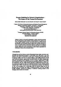
The Extended OPEN Process Framework The OPEN Process Framework (OPF) consists of (i) a process metamodel or framework from which can be generated an organizationally-specific process (instance) together with (ii) a repository and (iii) sets of construction guidelines. The metamodel can be said to be at the M2 metalevel (Figure 1) with both the repository contents and the constructed process instance at the M1 level. The M0 level in Figure 1 represents the execution of the organization’s (M1) process on a single project. Each (M1) process instance is created by choosing specific process components from the OPF Repository (Figure 1) and constructing (using the Construction Guidelines) a specific configuration – the “personalized OO development process”. Further minor modifications (“tailoring”) ensure a perfect fit of the individually created development process to the needs of a particular project. OPF’s Metamodel
OPF Repository containing Individual Process Component Descriptions
Constructed Process or Process Instance
Implemented Process(es)
M2
M1
M0
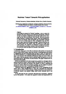
Figure 1 Three metalevels (M2, M1, M0) which provide a framework in which the relationship between the metamodel (M2), the repository and process instances (M1) and the implemented process (M0) can be seen to co-exist. The major meta-elements in the OPF metamodel are (Figure 2) Work Unit, Work Product and Producer. Together, Work Units and Producers create Work Products and the whole process is structured temporally by the use of Stages (phases, cycles etc. – see Figure 3). There are three important kinds of Work Unit: Activity, Task and Technique. Activities and Tasks say “what” is to be done and Techniques say “how” it will be accomplished. Stages state how these Work Units (particularly the Activities) are sequenced in time.
2
Stage provide macro organization to the
Essential Process Components
help to
Guidelines
For each element (represented by box), OPEN permits the user to select how many and which instances will be used. The OPF documentation provides a comprehensive list of suggestions on the best selections together with guidelines on their best organization.
Producer
perform
produce
create evaluate iterate maintain
Work Unit
Work Product
are documented using Language
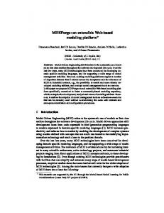
Figure 2 The five major metatypes in the OPF metamodel (based on [11]) Cycle
M2
M1
Life Cycle
1..*
+ 1..*
Specified Phases +
1..*
+
Development Cycle Selected LifeCycle Model
Build
Build
Milestone
Figure 3 The metaelements in the OPF metamodel relating to large scale temporal sequencing. These are all subtypes of the major metaelement called Stage (see Figure 2) (after [11]) As a consequence of the modular nature of the OPEN approach to methodology, via the notion of a repository of process components together with the application of process engineering [12], it is relatively easy to add additional meta-elements and extremely easy to
3
add additional examples of process components to the repository (as instances of preexisting meta-elements). To extend this approach to support agent-oriented information systems, Debenham and Henderson-Sellers [5] analyzed the differences between agentoriented and object-oriented approaches in order to be able to itemize and outline the necessary additions to the OPEN Process Framework’s repository in the standard format provided in [13]. The focus of this work was primarily on instances of the meta-class WorkUnit that are useful for agent-oriented methodologies and processes – the list of Tasks and Techniques necessarily added to the OPF repository is given in Table 1 (no new Activities are required). These new Tasks and Techniques were identified from the literature on agents and then checked against the case studies described later in this paper. However, we should also note that, while new M1 process components needed to be added to the repository, there was no need to make any changes or additions to the M2 level metamodel of the OPEN Process Framework [11]. Table 1 Tasks and Techniques added to the OPF repository to support the development of agent-oriented information systems (* indicates Techniques not identified in [5] but introduced here).
Tasks for AOIS
Identify agents’ roles Model the agent’s environment Identify system organization Determine agent interaction protocol Determine delegation strategy Determine agent communication protocol Determine conceptual architecture Determine agent reasoning Determine control architecture
Determine system operation Gather performance knowledge Determine security policy for agents Undertake agent personalization Identify emergent behaviour
Techniques likely to be useful Environmental evaluation* Environmental evaluation* Environmental evaluation* Contract nets Market mechanisms FIPA KIF compliant language* 3–layer BDI model* Deliberative reasoning: Plans Reactive reasoning: ECA Rules Belief revision of agents Commitment management Activity scheduling Task selection by agents Control architecture Learning strategies for agents [topic of future research] Environmental evaluation* User model incorporation* [topic of future research]
There are clear advantages in using a componentized process model together with the skills of process and method engineering when extensions, such as those discussed here,
4
are required or anticipated. OPEN provides a high degree of flexibility to the user organization in creating its software development process. Part of that flexibility is clear in the ready extension to support agent-oriented information systems developments. In comparison, pre-constructed (M1) methodologies suffer from their inflexibility. In the following sections, we exemplify the use of several of the newly proposed Tasks and Techniques in the context of business processes. Two case studies are described. The first considers a task-driven process management system and the second a goal-driven process management system.
Case Study 1. Business process management is a suitable area for multiagent systems [14-16]. Both of the case studies consider the management of different types of business process. To avoid a lengthy description, the subject of both case studies involves the processing of a loan application by a bank. This is a typically a workflow or “task-driven” process. A task-driven process can be associated with a, possibly conditional, sequence of activities such that execution of the corresponding sequence of tasks “always” achieves the process goal. The idea behind task-driven processes is that process failure will not happen. A workflow application in a draconian organisation may be seen to be failureproof and so could be treated as task-driven. In practice, even production workflow applications can fail; a clerk can “click the wrong button” for example. Each of these activities has a goal and is associated with a task that, on its termination, “always” achieves this goal. The same example is used for both the design of a single agent system and the design of a multiagent system (see second case study). application checked[ OK ] / remove from checker and enter on assessor application being assessed assessment timed out[ ] / remove from assessor and enter on supervisor application being assessed urgently
assessment complete[ risky ] / remove from assessor and enter on scrutiniser
application being scrutinised
assessment complete[ not risky ] / remove from assessor and enter on loans officer offer being made
Figure 4. Partial statechart for loan application process Task-driven processes can conveniently be modelled using statecharts [OPEN Technique: State modeling]. For example, Figure 4 shows part of a statechart for a loan application where the primitives “remove” and “enter” add and delete pointers in this way.
5
For a task-driven process, the completion of an activity in any state is equated to the realisation of the activity’s goal. Thus, the only way that a process instance will not progress is if its activity is aborted for some reason such as time constraints. In Figure 4 the event “assessment timed out” deals with such an eventuality. The resulting statechart is implemented simply as event-condition-action state-transition rules. Task-driven process management can be effected using a single reactive agent or expert system containing rules of this form. If the rules in such a knowledge base are indexed by their “from” state then the maintenance of the knowledge base is quite manageable. For example, the “top” transition in Figure 4 is: if in state(application being assessed) and event(assessment complete) occurs and condition(application assessed risky) is true then perform action(remove from assessor’s and add to scrutiniser’s “In Tray”) and enter state (application being scrutinised). The state label can be quite complex. For example, a state label for a process that is to be circulated amongst n people, two at a time, until some event occurs can be represented as an n * 2 matrix. System Objective and Environment and Organization The system objective is to manage the processes modelled above. The environment [OPEN Task: Model the agent’s environment] consists of users, assumed to have personal computing equipment with a web browser. The system organization consists of a singleagent system simply managing the (task-driven) processes. The Conceptual Architecture, the Control Architecture and System Operation. The conceptual architecture is a reactive architecture i.e. it does not support proactive, feed-forward reasoning because there is no such need in task-driven processes. All that the system has to do is to implement the event-condition-action state-transition rules described above. The control architecture is to trigger rules in the order in which the triggering events occur. In this simple example, there are no issues to decide for system operation; whereas in Case Study 2 the system operation receives considerably more attention.
Case Study 2. A goal-driven process has a process goal, and can be associated with a, possibly conditional, sequence of sub-goals such that achievement of this sequence “always” achieves the process goal. Achievement of a sub-process goal is the termination condition for that sub-process. Each of these sub-goals is associated with at least one activity and so with at least one task. Some of these tasks may work better than others
6
and there may be no way of knowing which is which. A task for an activity may fail outright or may be otherwise ineffective at achieving its goal. In other words, unpredictable task failure is a feature of goal-driven processes. If a task fails, then another way to achieve its sub-goal may be sought. Goal-driven processes [OPEN Task: Identify agents’ goals] may be modelled as state and activity charts [17]. The primitives of that model are activities and states. Figure 5 shows a simplified view of the management of goal-driven processes, in which the primitives are goals and plans. Plans are state transition diagrams in which there is one node labelled ‘start’, other nodes are labelled with states and from them are from two to four arcs. There is an arc labelled with ‘3’, which is followed if the state is achieved, and an arc labelled with ‘8’ which is followed if the state is not achieved. An example of a plan is shown in Figure 6. There may be an arc labelled with ‘A’ which is followed if the attempt to achieve the state is aborted and there may be an arc labelled ‘?’ which is followed if it is not known whether the state is achieved. Some goals are associated with executable activities and so with tasks. If a goal is not associated with an activity then it should be the subject of at least one plan. Figure 5 presents a simplified view because a sub-goal of a goal-driven process goal will not necessarily be goal-driven; aborting plans is also ignored. Plan
Select Process Knowledge (knowledge of how much the instance has/should cost etc)
Identify
?not SC and not activity goal? Process Goal Next-Goal (what we are trying (what to try to to achieve over all) achieve next) ?activity ?SC? goal?
Performance Knowledge (knowledge of how effective plans are)
Initialise
Back-up
Add to
Evaluate it
New Process Knowledge
Select
Identify
Procedure Do it
Add to
New Performance Knowledge
Figure 5. Goal-driven process management (simplified view) An activity chart specifies the data flow between activities. An activity chart is a directed graph in which the arcs are annotated with data items. A state chart is a representation of a finite state machine in which the transitions annotated with eventcondition-action rules – see Figure 4. Muth et al. [17] show that the state and activity chart representation may be decomposed to pre-empt a distributed implementation. Each event on a state chart may be associated with a goal to achieve that event, and so a state
7
Assess_application[ Application X has been dealt with in time τ ]
•
start
Application X assessed (RESULT = X ) by time ( NOW + τ – ∆ )
RESULT = OK
3
8
RESULT = ¢ OK
Acknowledgement for application X received from Loans agent by time ( NOW + ∆ ) 3
/ AdU( #1 )
8
Acknowledgement for application X received from Supervisor agent by time ( NOW + ∆ )
Acknowledgement for application X received from Scrutiniser agent by time ( NOW + ∆ )
/ AdU( #3 ) 8
3
8
3
/ AdU( #2 ) 3 3
8
3
8 8
Figure 6. Plan for assessment example illustrated in Figure 4. chart may be converted to a plan whose nodes are labelled with such goals. Unlike taskdriven processes, the successful execution of a plan for a goal-driven process is not necessarily related to the achievement of its goal. One reason for this is that an instance may make progress outside the process management system — two players could go for lunch for example. That is, when managing goal-driven processes, there may be no way of knowing the “best” task to do next. Each high-level plan for a goal-driven process should terminate with a check of whether its goal has been achieved. To represent goal-driven processes, a form of plan is required that can accommodate failure. Thus, goal-driven process management has a requirement both for a software architecture that can cope naturally with failure and for some technique for intelligently selecting which is the “best” task to do next [18] [OPEN Task: Determine conceptual architecture; OPEN Technique: Task selection by agents]. Any general-purpose architecture can achieve this first requirement but the process architecture described below is particularly suitable. The System Objective, Environment and Organization In the goal-driven process management system, an agent supports each (human) user. These agents manage their users’ work and manage the work that a user has delegated to another user/agent pair. Sub-process delegation [OPEN Technique: Delegation analysis] is the transfer of responsibility for a sub-process from one agent to another. A delegation strategy decides to whom to give responsibility for doing what. Delegation strategies in manual systems can be quite elementary; delegation is a job at which some humans are not very good. A user of the system may specify the delegation strategy and may permit her agent to delegate for her, or may delegate manually. In doing this, the user has
8
considerable flexibility first in defining payoff and second in specifying the strategy itself. A delegation strategy may attempt to balance some of the three conflicting principles: maximising payoff, maximising opportunities for poor performers to improve and balancing workload [19]. The objective of the system is to manage goal-driven processes with a specified interation protocol and communication protocol [OPEN Tasks: Determine agent interaction protocol; Determine communication protocol]. The system’s organization consists of one agent for each (human) user; the role of each agent is that of an assistant to its user. The user interacts with a virtual work area and a virtual diary. The work area contains three components: the process instances awaiting the attention of the user, the process instances for which the user has delegated responsibility to another agent and the process instances that the agent does not understand. The diary contains the scheduled commitments of the user. The agent manages the work area and may also interact with the diary. The Conceptual Architecture One well-documented class of hybrid architectures is the three-layer, BDI agent architectures. One member of this class is the INTERRA P conceptual architecture [20], which has its origins in the work of [21]. In the goal-directed process management system, however, the agent’s conceptual architecture differs slightly from the INTERRA P conceptual architecture; it is intended specifically for business process applications. It consists of a three-layer BDI architecture together with a message area, managed by a message manager. Access to the message area is given to other agents in the system who may post messages there and, if they wish, may remove messages that they have posted. The idea behind the message area is to establish a persistent part of the agent to which the other agents have access. This avoids other agents tampering directly with an agent’s beliefs and enables agents to freely remove their messages from a receiving agent’s message board if they wish. The message area is rather like a person’s office “in-tray” into which agents may place documents and from which they may remove those documents if they wish. The agents’ world beliefs are derived either from reading messages received from a user or from reading the documents involved in the process instance or from reading messages in the message area. These activities are fundamentally different in that documents are “passive”; they are read only when information is required. Users and other agents send messages when they feel like it. Beliefs play two roles. First, they may be partly or wholly responsible for activating a local or cooperative trigger that leads to the agent committing to a goal and may thus initiate an intention (e.g. a plan to achieve what a message asks, such as “please do xyz”). This is part of the deliberative reasoning mechanism [OPEN Task: Determine reasoning strategy for agents]. Second, they can be partly or wholly responsible for activating a reactive procedure trigger that, for example, enables the execution of an active plan to progress. This is part of the reactive reasoning mechanism.
9
Deliberative Reasoning The form of plan used here is slightly more elaborate than the form of agent plan described in [21] where plans are built from single-entry, triple-exit blocks. Powerful though that approach is, it is inappropriate for process management since in this case whether a plan has executed successfully is not necessarily related to whether that plan’s goal has been achieved. Consider now the management of the same process as in the first case study (Figure 4) and consider the agent for the Assessor. That agent may have a plan similar to that shown in Figure 6, which shows how constraints are dealt with in that formalism in which interagent communication [OPEN Task: Determine communication protocol] has to be considered. Three “fail actions” are shown in Figure AdU” is a hard-wired action that means “advise the agent’s user” with the corresponding error message signalling that some calamity has occurred. In this example, the three hard-wired actions indicate that no acknowledgment was received from the three respective agents within some pre-set time ∆. No “?” or “A” states are shown in Figure 6; for each of the four sub-goals the “7” should be entered in lieu of an abort or unknown state. Reactive Reasoning Reactive reasoning play two roles in this case study: first, if a plan is aborted then its abort action is activated; second, if a procedure trigger fires then its procedure is activated — this includes hard wired procedure triggers that deal with urgent messages such as “the building is on fire!”. Of these two roles, the first takes precedence over the second. The Control Architecture The control architecture is essentially the INTERRA P control architecture. In outline, the deliberative reasoning mechanism employs the non-deterministic procedure: • “on the basis of current beliefs — identify the current options, • on the basis of current options and existing commitments — select the current commitments (or goals), • for each newly-committed goal choose a plan for that goal, • from the selected plans choose a consistent set of things to do next (called the agent’s intentions)”. The reactive reasoning mechanism takes precedence over the deliberative reasoning mechanism. The reactive frequency is the frequency at which an attempt is made to fire all active reactive triggers. The reactive frequency here is thirty seconds. The deliberative frequency is the frequency at which the deliberative reasoning mechanism is activated. To maintain some stability in each user’s work area, the deliberative frequency is prescribed as five minutes.
10
The System Operation For goal-directed processes, there may be no way of knowing what the “best” thing to do next is, and that next thing may involve delegating the responsibility for a sub-process to another agent[22]. This raises two related issues: selection and delegation – OPEN Task: Determine the delegation strategy [5]. In the absence of a satisfactory meaning of “best” and with only the performance knowledge to guide the decisions, the approach taken to plan/activity selection is to ask the user to provide a utility function defined in terms of the performance parameters. If this utility function is a combination of (assumed) normal parameters then a reasonable plan/activity selection strategy [OPEN Task: Identify agents’ goals] is given a goal to choose each plan (or activity) from the available plans (activities) with the probability that that plan (activity) has the highest expected utility value. Using this strategy even poor plans have a chance of being selected, and, maybe, performing better than expected. Contract nets [OPEN Technique: Contract nets] with focussed addressing are often used to manage semi-manual or automatic delegation. The selection of a plan to achieve a next goal typically involves deciding what to do and selecting who to ask to assist in doing it. The selection of what to do and who to do it can not be subdivided because one person may be good and one form of task and bad at others. So the “what” and the “who” are considered together. The system provides assistance in making this decision. There are two basic modes in which the selection of “who” to ask is done. First the authoritarian mode in which an individual is told to do something. Second the negotiation mode in which individuals are asked to express an interest in doing something, a mode implemented using contract nets with focussed addressing [23]. When contact net bids are received, the successful bidder has to be identified. The use of a multi-agent system to manage processes expands the range of feasible strategies for delegation from the authoritarian strategies described above to strategies based on negotiation between individuals. Negotiation-based strategies that involve negotiation for each process instance are not feasible in manual systems for everyday tasks due to the cost of negotiation. If the agents in an agent-based system are responsible for this negotiation then the cost of negotiation may be negligible. If the agent making a bid to perform a task has a plan for achieving that task, then the user may permit the agent to construct the bid automatically. A bid consists of the five pairs of real numbers (Constraint, Allocate, Success, Cost, Time). The pair constraint is an estimate of the earliest time that the individual could address the task (i.e. ignoring other non-urgent things to be done) and an estimate of the time that the individual would normally address the task if it “took its place in the in-tray”. The pairs Allocate, Success, Cost and Time are estimates of the mean and standard deviation of the corresponding parameters as described above. A delegation strategy is a strategy for deciding who to give responsibility to for doing what. A user specifies the delegation strategy that is used by the user’s agent to evaluate bids. In doing this the user has considerable flexibility first in defining payoff and second in specifying the strategy itself. Practical strategies in manual systems can be quite
11
elementary; delegation is a job which some humans are not very good at. A delegation strategy may attempt to balance some of the three conflicting principles: maximising payoff, maximising opportunities for poor performers to improve and balancing workload. Payoff is defined by the user and could be some combination of the expected value added to the process, the expected time and/or cost to deal with the process, and the expected likelihood of the process leading to a satisfactory conclusion [24].
Assessment The applications built are distributed multiagent systems. This enables the management of complex tasks to be handled as each node is individually responsible for the way in which it goes about its business. That is, the plan in each agent only has to deal with the goals that that agent has to achieve. For example, Figure 6 shows a complete high-level plan for an Assessor agent. This simplifies the design of plans for the agents. As a system built from autonomous components, each node in the goal-driven system has to cope with the unexpected failure of other nodes. This complicates the design of the plans. In the delegation strategy, an over-riding principle is to determine how delegation is to be dealt with no matter what parameters are used to support it. For example, if A delegates the responsibility for a sub-process to B who, in turn, delegates the same sub-process to C then should B advise A of this second delegation — thus removing B from the responsibility chain — or should B remain in the responsibility chain? Distributed, goal-driven systems are considerably more expensive (approximately four times the programming effort) to build than task-driven systems. Having made this investment, dividends flow from the comparative ease by which new processes are included, in that only those agents involved in a process need to develop plans to cope with that process. There is also a negative here. The system has grown around a principle of personalisation i.e. each individual is responsible for deciding how their agent operates. This means that similar plans may be constructed at a number of nodes by the users at those nodes to deal with the same sub-process. One way of managing this is to publish solutions as they are constructed, but that has not been considered. Evaluation To illustrate the differences between the four strategies best, prob, random and circulate they are are evaluated in a laboratory experiment. A world has been designed in which the relative performance of these four strategies are simulated. There are always three individuals in this world. If individuals die (i.e. they become unavailable) then they are replaced with new individuals. At each cycle—i.e. a discrete time unit—one delegation is made. There is a natural death rate of 5% for each individual for each cycle. The payoff of each individual commences at 0 and improves by 10% of “what there is still to learn” on each occasion that an individual is delegated
12
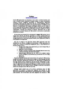
responsibility. So an individual’s recorded payoff is progressively: 0, 0.1, 0.19, 0.271, 0.3439, and so on, tending to 1.0 in the long term. The mean and standard deviation estimates of expected payoff are calculated as described above using a value of α = 0.6. In addition, the individuals have a strength of belief of the extent to which they are being given more work than the other two individuals in the experiment. This strength of belief is multiplied by a “rebel” factor and is added to the base death rate of 5%. So if work is repeatedly delegated to one individual then the probability of that individual dying increases up to a limit of the rebel factor plus 5%. A triple duplication occurs when work is delegated to the same individual three cycles running. The proportion of triple duplications is used as a measure of the lack of perceived recent equity in the allocation of responsibility. The payoff and proportion of triple duplications for the four strategies are shown against the rebel factor on the top and bottom graphs respectively in Figure 7. The simulation run for each value is 2000 cycles. The lack of smoothness of the graphs is partially due to the pseudo-random number generator used. When the rebel factor is 0.15 (i.e. three times the natural death rate) all four strategies deliver approximately the same payoff. The two graphs indicate that the prob strategy does a reasonable job at maximising payoff while keeping triple duplications reasonably low for a rebel factor of < 0.15. However, prob may only be used when the chosen definition of payoff is normally distributed. The strategy best also assumes normality; its definition may be changed to “such that the expected payoff is greatest” when payoff is not normal. 0.7 0.65 0.6 0.55 0.5
Best
Prob
1
0.45
0.8
0.4 Circ
0.35
Best
0.6 0.4
Rand Circ 0.4
0.3
0.2
0.15
0.1
0.075
0.05
0 0.025
0.4
0.3
0.2
0.15
0.1
0.075
0.05
0.025
0.0125
0
Prob
0.2 0.0125
Rand
0
0.3 0.25
Figure 7. Payoff (left figure) and triple duplications (right figure) against the rebel factor for a learning rate = 0.1, death factor = 0.05, and α = 0.6.
Summary and Further Work The application of the extended OPEN Process Framework has been exemplified only in terms of its support for particular Tasks and Techniques, mostly at the design level. This worked well. While no changes to the metamodel were found necessary, further details need to be researched for the process components (particularly Tasks and Techniques) related to the detailed design of agents; for example, to describe autonomy, intelligence, social abilities and perhaps mobility. While the initial methdological extensions are promising, there is still much methodology refinement that is necessary before full
13
methodological support for agent-oriented software development becomes commercially available. Proposed extensions (new Tasks and Techniques for OPEN) have been illustrated in two case studies of business processes. The selection of tasks and delegation of responsibility amongst the agents were also considered. Future evaluations need to create a full lifecycle development process, which will include not only technical but management issues including a well-specified lifecycle model, such as the ContractDriven Lifecycle (CDLC) model generally advocated for use in OPEN process instances. The CDLC (or other) lifecycle model adds concepts such as stages, phases, builds, milestones as project management focussed sequencing superimposed upon the technical Activity/Task interfacing and sequencing discussed here.
Acknowledgements This is Contribution number 02/08 of the Centre for Object Technology Applications and Research (COTAR) of the University of Technology, Sydney
References 1. Jennings, N. (2001). Agent of change. Application Development Advisor, 5(3), 6. 2. Wooldridge, M. (1997). Agent-based software engineering, IEE Procs Software Eng., 144, 26-37. 3. Jennings, N.R. and Wooldridge, M. (2001). Agent-oriented software engineering. In J. Bradshaw (ed.), Handbook of agent technology (in the press). Cambridge, MA, USA: AAAI/MIT Press. 4. Wooldridge, M., Jennings, N.R. and Kinny, D. (2000). The Gaia methodology for agentoriented analysis and design. J. Autonomous Agents and Multi-Agent Systems, 3, 285-312. 5. Debenham, J. and Henderson-Sellers, B. (2002). Designing agent-based process systems – extending the OPEN Process Framework, in Intelligent Agent Software Engineering (ed. V. Plekhanova), Idea Group Publishing (in press) 6. Wooldridge, M. and Ciancarini, P. (2001). Agent-oriented software engineering: the state of the art. In Agent-oriented software engineering. P. Ciancarini and M. Wooldridge (eds.) (pp. 1-28). Berlin, Germany: Springer Verlag. 7. Odell, J., Van Dyke Parunak, H. and Bauer, B. (2000). Extending UML for agents. In G. Wagner, Y. Lesperance and E. Yu (eds.), Procs. Agent-Oriented Information Systems Workshop, 17th National Conference on Artificial Intelligence (pp. 3-17). Austin, TX, USA. 8. OMG (1999). “OMG Unified Modeling Language Specification”, Version 1.3, June 1999, OMG document ad/99-06-09 [released to the general public as OMG document formal/00-03-01 in March 2000]. Available at http://www.omg.org
14
9. OMG (2001). OMG Unified Modeling Language Specification, Version 1.4, September 2001, OMG document formal/01-09-68 through 80 (13 documents) [Online]. Available http://www.omg.org 10. Graham, I., Henderson-Sellers, B. and Younessi, H. (1997). The OPEN Process Specification. Harlow, UK: Addison-Wesley. 11. Firesmith, D.G. and Henderson-Sellers, B. (2002). The OPEN Process Framework. An Introduction. Harlow, UK: Addison-Wesley. 12. Rupprecht, C., Fünffinger, M., Knublauch, H. and Rose, T. (2000). Capture and dissemination of experience about the construction of engineering processes, Procs CaiSE 2000, LNCS 1789, 294-308 13. Henderson-Sellers, B., Simons, A.J.H. and Younessi, H. (1998). The OPEN Toolbox of Techniques. Harlow, UK: Addison-Wesley. 14. Jennings, N.R., Sycara, K. and Wooldridge, M. (1998). A roadmap of agent research and development. Int. Journal of Autonomous Agents and Multi-Agent Systems, 1 (1), 7-38. 15. Jennings, N.R., Faratin, P., Norman, T.J., O’Brien, P. and Odgers, B. (2000). Autonomous agents for business process management. Int. J. Applied Artificial Intelligence, 14 (2), 145-189. 16. Koudouridis , G., Corley, S., Dennis, M., Ouzounis , V., Van Laenen, F., Garijo, F. and Reynolds, H. (2001). Communications management process integration using software agents: a specification of a framework for agent oriented workflow management systems. EURESCOM Project P815. http://www.eurescom.de/public/projectresults/P800-series/815d1.htm 17. Muth, P., Wodtke, D., Weißenfels , J., Kotz D.A. and Weikum, G. (1998). From centralized workflow specification to distributed workflow execution. J. Intelligent Information Systems, 10 (2), 159-184. 18. Debenham, J.K. (2000). Supporting strategic process. In Proceedings Fifth International Conference on The Practical Application of Intelligent Agents and Multi-Agents (pp. 237-256). Manchester, UK. 19. Wooldridge, M. and Jennings, N.R. (1998). Pitfalls of agent-oriented development. In Procs. 2nd Int. Conf. on Autonomous Agents (pp. 385-391). Minneapolis/St. Paul, MN, USA. 20. Müller, J.P. (1996). The design of intelligent agents. Berlin, Germany: Springer-Verlag. 21. Rao, A.S. and Georgeff, M.P. (1995). BDI agents: from theory to practice. In Procs. First International Conference on Multi-Agent Systems (pp. 312-319). San Francisco, CA, USA. 22. Lind, J. (2001). Iterative software engineering for multiagent systems: the Massive method. Berlin, German: Springer Verlag. 23. Weiss, G. (Ed). (1999). Multi-agent systems. Cambridge, MA, USA: The MIT Press. 24. Koriche, F. (1998), Approximate reasoning about combined knowledge. In Intelligent Agents IV, Singh M.P, Rao, A. and Wooldridge, M.J. (Eds.), Springer Verlag.
15