The kDRR Scheduling Algorithms for Multi-server Packet Switches Mei Yang † , S. Q. Zheng
∗†
and Dominique Verchere‡
∗ Department of Electrical Engineering † Department of Computer Science University of Texas at Dallas, Richardson, TX 75083-0688, USA {sizheng, meiyang}@utdallas.edu ‡ Research & Innovation, Alcatel USA, Plano, Texas 75075, USA
[email protected]
Output port 0
Input port 0
0 0
0
1
1
K-1
K-1
N-1
1
...
1
...
0
N-1 ...
0
Output port N-1
0
0
1
1
K-1
K-1
1
N-1
OSM
0 1 ...
... Input port N-1
...
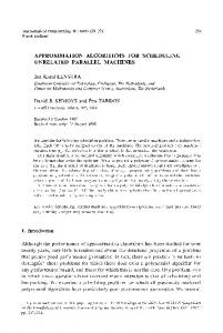
The exponential increase of Internet traffic demands high speed, large capacity IP switch routers. As the key to the success of the next generation Internet (NGI), terabit IP switch routers have received attention from both research and commercial communities. In [5], Chao etc. reviewed several gigabit IP switch routers, optical packet switch architectures and opto-electronic packet switches. Combining the strength of both optical and electronic technologies, opto-electronic packet switches are proposed to be a competitive architecture for terabit IP switch routers [5]. In [3], [4], a new opto-electronic packet switch architecture with terabit capacity was proposed. This switch architecture employs an optical switching matrix (OSM) to interconnect multiple electronic input/output modules. IP packets are decomposed into fixed-size cells as they arrive at line cards (LCs), buffered at data concentrator cards (DCCs), transferred through the optical switching matrix, and then reassembled into IP packets before they depart from LCs. Each DCC connects to multiple LCs. On each DCC, cells are buffered into virtual output queues (VOQs) according to their destination DCCs to avoid the problem of head-of-line (HoL) blocking [11]. Within a VOQ, cells are composed into larger, fixed-size composite packets (CPs) to be transferred through the OSM in one switch slot. Using WDM technology, the optical path between a DCC and the OSM can carry multiple optical channels (wavelengths) simultaneously. The number of wavelengths available and bandwidth of each wavelength decide the switch capacity. Taking the example of a switch of 16 DCCs, assume each DCC connects with the OSM with 16 wavelengths, each carrying 10Gbps. The total switch capacity is 2.56Tbps. We abstract each DCC as a port. Assume the number of wavelengths on each port is equal to the number of LCs connecting to each port and the bandwidth of each wavelength is equal to the aggregated bandwidth of one LC in one switch slot. A group of wavelengths and their associated buffers are composed as a service
...
Introduction
...
1
...
Key words: Multi-server switch architectures, kDRR scheduling algorithms, K-matching, programmable k-selectors.
unit, named a server. Since the total switch capacity is fixed, different number of servers provide different granularity of services. The more number of servers, the finer the granularity [9]. Figure 1 illustrates an abstracted N × N switch model with each port carrying K servers. A cell slot is the time unit during the arrivals of two successive cells on one LC. A switch slot is the time unit between two successive operations of the optical switching matrix. One switch slot is equal to multiple cell slots. During each switch slot, the central scheduler computes a conflict-free matching between input port servers and output port servers and configures the switching matrix. The multi-server switch architecture also imposes special requirements on the scheduling algorithm running in the central scheduler. Three scheduling algorithms have been proposed in [9] for the multi-server switch architecture, including multiSLIP, FR-DRR and PDRR. However, the difference between multi-server switch scheduling and single-server scheduling is not clearly studied. And how to implement these algorithms at high speed is still a problem. In [9], implementation schemes using programmable priority encoders (PPE) [10] were discussed. Since PPE can only make one selection each time, we need run PPE K times to select K requests in each phase of the algorithm. Such an implementation is not desired for packet switches with high line rate and/or large K’s.
...
Abstract— Tremendous increase of Internet traffic demands high speed, large capacity IP switch routers. The introduction of multi-server switch architectures not only makes it possible to scale to larger switch capacities, but also imposes special requirements on scheduling algorithms running in the central scheduler. In this paper, we model the multi-server switch scheduling problem as a maximum bipartite K-matching problem. We generalize iSLIP and DRR to multi-server switch architectures and propose two distributed scheduling algorithms kDRR RGA and kDRR RG for finding maximal K-matchings. Through simulations, we show that both algorithms achieve comparable performance with high throughput under uniform traffic. Using programmable k-selectors, kDRR RGA and kDRR RG are ready to be implemented at high speed.
N-1
Fig. 1. Abstraction of the multi-server switch architecture. In this paper, we first define the scheduling problem on the multi-server switch architecture as a maximum K-matching problem on a bipartite graph. Since maximum size K-matching algorithms are hard to implement and can cause unfairness, we generalize iSLIP and DRR to the multi-server switch architecture and present two distributed iterative scheduling algorithms, kDRR RGA and kDRR RG, for finding maximal K-matchings between inputs and outputs. Because these two algorithms are equivalent statistically under unform traffic, we take the example of
kDRR RGA and study its performance of with uniform Bernoulli arrivals and uniform bursty arrivals. Simulation results of 16 × 16 switch show that kDRR RGA achieves up to 100% throughput with both Bernoulli arrivals and bursty arrivals. Compared to multiSLIP, kDRR RGA performs better with one or two iterations and it needs less average number of iterations to converge. We show that the implementation of kDRR algorithms is much simpler than multiSLIP. Using programmable k-selectors [15], both kDRR RGA and kDRR RG are ready to be implemented at high speed. The time and area complexity of such an implementation is independent of K.
2
Problem Statement
Our study is focused on scheduling algorithms of an N × N multiserver switch architecture as shown in Figure 1. In our study, we assume each input/output port connects to N input/output LCs. Each input port maintains N VOQs, denoted as Qi,j , where i is the input port no., j is the output port no., 0 ≤ i, j ≤ N − 1. Each output port maintains N output queues (OQs), each OQ is associated with an output LC. Let T be the switch slot time and T 0 be the cell slot, we have T = N 0 T 0 , where N 0 ≥ N . In each cell slot, either one cell or none cell comes from one LC. Thus, during one switch slot, at most N 0 N cells enter in one input port. Assume K is the number of servers on each input/output port, during each switch slot, each server can transfer a CP, which consists of N/K elementary composite packets (ECP). Each ECP is composed of N 0 cells. The composition of a CP is shown in Figure 2 [9]. Thus, the total service capacity of an input port is N 0 N cells while the service rate of each server is given by N 0 N/K cells per switch slot. CP ECP #N/K-1 N'-1 ... 1
0
ECP #0
...
N'-1 ... 1
0
Fig. 2. The structure of a CP To fully utilize the switch capacity, it is desirable to transfer only full CPs. The delay specification of a high speed packet switch requires that the probability, of the transit time of all incoming data exceeding a statistical delay bound, is limited to a small value [3]. Thus, it may be necessary to sacrifice some switch capacity to transfer packets that will grow stale. Under low traffic load, non-full and non-stale packets should be served if there are still available servers. As a result, the switch scheduling algorithm that decides, in each switch slot, what requests should be generated and what connections should be made between input port servers and output port servers are extremely important for the performance of the switch. The scheduling problem on the multi-server switch architecture can be modelled as a K-matching problem on the bipartite graph G = (V, E), where • V = V1 ∪ V2 , V1 = {input ports},V2 = {output ports}, N =| V1 |=| V2 |. • E = {connection requests from input ports to output ports}, M =| E |. A K-matching K ⊆ E such that no node of G is incident with more than K edges in K. A maximum size K-matching is one with the maximum number of edges, while a maximal size K-matching is one that no more edges can be trivially added. A perfect Kmatching is one that each node is incident with K edges in K. Figure 3 gives an example of a maximum 2-matching and a maximal 2-matching of a 4 × 4 switch. With this maximum 2-matching, Q0,0 , Q0,2 , Q1,1 , Q1,3 and Q2,1 will be served.
Input
Output
Input
Input
Output
Output
0
0
0
0
0
0
1
1
1
1
1
1
2
2
2
2
2
2
3
3 3 (b) Maximum 2-matching graph
3 (a) Request graph
3
3 (c) Maximal 2-matching graph
Fig. 3. A maximum and maximal 2-matching of a 4 × 4 switch.
The maximum size K-matching (MKM) problem can be taken as a special case of the bipartite b-matching problem [8], [17]. The MKM problem can be solved by the generalized augmenting path algorithm with time complexity of O(KN M ) [14]. It can also be transformed to a maximum-flow problem in O(M ) time. Since the transformed flow network is a unit network [16], we can use Dinic’s algorithm to solve the corresponding maximum-flow prob√ lem in O( N M ) time [16]. However, these MKM algorithms are too complex to be implemented in high speed packet switches. Another noticeable problem with maximum size K-matching is that it may cause unfairness. For example, in Figure 3, if Q0,0 , Q0,2 , Q1,1 , Q1,3 and Q2,1 continue having requests and other VOQs continue having no requests in successive switch slots, then Q0,1 may get starved since edge (0, 1) is not in any maximum 2-matchings. For practical use, we desire scheduling algorithms with high throughput, starvation free, fast speed and simple implementation [13]. A maximal K-matching is a good option other than a maximum K-matching. Maximal matching scheduling algorithms proposed for input-buffered switches include PIM [1], RRM, iSLIP [13], DRR [6], and iterative ping-pong arbitration scheme [7], etc.. Among these scheduling algorithms, iSLIP and DRR can achieve up to 100% throughput under uniform traffic and are readily implemented in hardware at high speed. In the following, we generalize the idea of iSLIP and DRR and present the k-server dualround-robin (kDRR) scheduling algorithms for multi-server switch architectures. These two scheduling algorithms use a distributed approach to find a maximal K-matching between input ports and output ports.
3
kDRR Algorithms
As iSLIP and DRR, kDRR algorithms are iterative and use rotating priority (”round-robin”) arbitration to schedule each active input and output in turn. Both kDRR RGA and kDRR RG adopt the conservative policy [4], in which requests are first generated for full CPs and non-full CPs with time-limit approaching and then for other non-full CPs if there are still available servers. Due to the space limit, here we only present kDRR with request, grant and accept (kDRR RGA). Another version, kDRR with request and grant (kDRR RG), can be constructed symmetrically. We use the following notations. Let Ii and Oj be the abstraction of N input ports N output ports respectively, where 0 ≤ i, j ≤ N − 1. For each Ii , let ai be its accept pointer, indicating its accept starting point, where 0 ≤ ai ≤ N − 1. For output Oj , let gaj be its issued grant pointer, indicating its issued grant starting point, where 0 ≤ gai ≤ N − 1. Let an N × N 0-1 matrix R be the request matrix, where Ri,j = 1 denotes Qi,j has a request. Let KIi and KOj denote the number of available servers at Ii and at Oj respectively. For the first iteration, ∀0 ≤ i, j ≤ N −1, KIi = K, and KOj = K. The three steps of kDRR RGA operate as follows. Request: ∀Ii , 0 ≤ i ≤ N − 1, if Ii has available servers and unresolved requests (requests to outputs with available servers), it sends all unresolved requests to their corresponding Oj0 s.
Switch slot 0
Grant: ∀Oj , 0 ≤ j ≤ N − 1 , if Oj has available servers and receives requests from any inputs, it issues min{KOj , number of requests to Oj } grants to requests, starting from gaj . The issued grants are sent to their corresponding Ii0 s. gaj is updated to one beyond (modulo N) the last granted input (starting from gaj in a circular manner) if and only if there are any grants accepted in the Accept phase of the first iteration. KOj is updated to the number of available servers at Oj . Accept: ∀Ii , 0 ≤ i ≤ N − 1 , if Ii has available servers and receives grants from any outputs, it accepts min{KIi , number of grants to Ii } issued grants starting from ai . ai is updated to one beyond(modulo N) the last accepted output. KIi is updated to the number of available servers at Ii .
Input a0=0
3 0 2 1
a0 0
3 0 2 1
a1 1
3 0 2 1
a2 2
3 0 2 1
a3 3
Output 0
1
3 0 2 1
3 0 2 1
2
3 0 2 1
3
3 0 2 1
Input
ga0 3 0 2 1
ga0
a1
ga2
3 0 2 1
3 0 2 1
ga3 3 0 2 1
3 0 2 1
3 0 2 1
a2 a3
Input
3 0 2 1
0
a1 1
3 0 2 1
1
3 0 2 1
2
2
3 0 2 1
3
3
ga2
Slot 2
ga1
a2
3 0 2 1
2
2
3 0 2 1
3
3
3 0 2 1
a3
ga2
ga3
ga1=2 a1=2
ga1=2 a =2 1
ga1=2
ga2=0 a2=0
ga2=0 a2=4
ga2=0 a =4 2
ga2=0
a3=0
ga3=0 a3=0
ga3=0 a3=4
ga3=0 a =4 3
ga3=0
a4=0
ga4=0 a =0 4
ga4=0 a4=0
ga4=0 a =6 4
ga4=0
a5=0
ga5=0 a5=0
ga5=0 a5=0
ga5=0 a5=6
ga5=0
a6=0
ga6=0 a6=0
ga6=0 a6=0
ga6=0 a =0 6
ga6=0
a7=0
ga7=0 a7=0
ga7=0 a7=0
ga7=0 a =0 7
Iteration 1
Iteration 2
Input Output ga0=4 a0=4
Input a0=4
Output ga0=4 ga1=4
a1=2
ga1=2
a1=4
ga1=4 a1=4
a2=4
ga2=0
a2=2
ga2=2 a2=2
ga2=2
a3=4
ga3=0
a3=2
ga3=2 a3=2
ga3=2
a4=6
ga4=0
a4=6
ga4=0 a4=6
ga4=0
a5=6
ga5=0
a5=6
ga5=0 a5=6
ga5=0
a6=0
ga6=0
a6=0
ga6=0 a6=0
ga6=0
a7=0
ga7=0
a7=0
ga7=0 a7=0
ga7=0
Iteration 1
Output ga0=4
Input a0=6
ga7=0 Iteration 3
Iteration 2 Switch slot 3
Output Input ga0=6 a =6 0
Switch slot 4
Output ga0=6
Output ga0=0
a1=4
ga1=4
a1=6
a1=0
ga1=0
a2=2
ga2=2
a2=4
ga2=4 a =4 2
ga2=4
a2=6
ga2=6
a3=2
ga3=2
a3=4
ga3=4 a =4 3
ga3=4
a3=6
ga3=6
a4=0
ga4=0
a4=2
ga4=2 a4=2
ga4=2
a4=4
ga4=4
a5=0
ga5=0
a5=2
ga5=2 a5=2
ga5=2
a5=4
ga5=4
a6=6
ga6=0
a6=0
ga6=0 a =0 6
ga6=0
a6=2
ga6=2
a7=6
ga7=0
a7=0
ga7=0 a =0 7
ga7=0
a7=2
Iteration 0
Iteration 1
Iteration 0
ga1=6
Input a0=0
ga1=6 a =6 1
ga7=2 Iteration 0
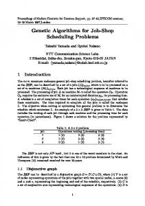
Fig. 5. Example of the number of iterations to converge for an 8 × 8 switch with saturated load
Slot 1 Output
0
1
1
Slot 0 a0
0
0
a0
ga1
Output ga0=2
ga1=0 a1=2
Input a0=4
3 0 2 1
Output Input ga0=2 a =2 0
a2=0
Iteration 0 Switch slot 2
Output
Output Input ga0=2 a0=2
a1=0
Iteration 0 Switch slot 1 Input Output ga0=2 a0=2
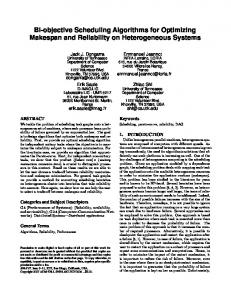
Figure 4 shows how kDRR RGA works for a 4 × 4 switch with saturated load. At the start of switch slot 0, assume ∀0 ≤ i ≤ 3, gai = 0, ∀0 ≤ j ≤ 3, aj = 0. Then after the scheduling, we get ga0 = 2, ga1 = 2, ga2 = 0, ga3 = 0, and a0 = 2, a1 = 2, a2 = 0, a3 = 0. Due to the desynchronization of issued grant pointers, we get a perfect 2-matching at switch slot 1 and thereafter. Under saturated load, kDRR RGA actually adapts to a time-division multiplexing scheme. Input
Input Output ga0=0 a0=2
ga3
3 0 2 1
3 0 2 1
Input
ga0
ga1
3 0 2 1
Output
0
a1
3 0 2 1
0 ga0
a0 3 0 2 1
3 0 2 1
3 0 2 1
3 0 2 1
1
1
2
2
3 0 2 1
3
3
3 0 2 1
a2
a3
ga1
ga2
ations for kDRR RGA to converge in switch slot 1 and 2 respectively. After switch slot 3, all arbitration components have become totally desynchronized and kDRR RGA converges in a single iteration.
ga3
4
Performance Evaluation
Slot 3
Fig. 4. Illustration of desynchronization effect of request pointers of kDRR RGA. kDRR RGA has the following properties. Property 1: At each output, due to the property of round-robin, the lowest priority element is set as the last input that accepts its issued grant in the first iteration. Property 2: Under saturated load, all VOQs with a common output have the same throughput. The issued grant pointer moves N to each input in a fixed order (every K switch slots), thus providing each with the same throughput. Property 3: kDRR RGA converges in at most N − K + 1 iterations. Convergence means that either there is no more requests or all input/output ports are matched, i.e., a maximal K-matching is founded. The explanation is as follows. We use N (R) to denote the total number of requests. There two cases: (1) If N (R) ≤ K 2 , then all requests will be accepted in one iteration. (2) If N (R) > K 2 , the maximal K-matching size is at most N K. The first iteration will accept at least K 2 requests. The last iteration will accept at least 1 request. In other iterations, at least K requests will be accepted. Thus, the total number of iterations needed is at most 2 −1 b N K−K c + 2, which is given by N − K + 1. K Figure 5 shows an example for an 8 × 8 switch with 2 servers at each input/output port with saturated load. In switch slot 0, kDRR RGA takes 4 iterations to converge. It takes 3 and 2 iter-
In the following, we will evaluate the performance of kDRR algorithms in terms of average transit time under uniform traffic. Before we present simulation results, we first give an analysis of the minimum average transit time on the given switch model.
4.1
Analysis
The minimum average transit time is obtained under such a situation that the service rate to each VOQ is proportional to its arrival rate. Under uniform traffic, each VOQ has the same average arrival rate. Thus, the minimum average transit time under uniform traffic is achieved with a scheduling algorithm that could serve each VOQ equally. An ideal case is that each VOQ is associated with a deterministic server, which can transmit 1 ECP (or N 0 cells) per switch slot. The average transit time through the switch is the sum of the average response time at the input port and at the output port. The average response time of a cell at the input port has three components: (1) The residual service time of cells to be transmitted, it is half a switch slot for deterministic server in average. (2) The waiting time of an incoming cell. It is computed as follows. The input sources to each input port are N independently, identically distributed (i.i.d.) Bernoulli sources. Let p denote the probability of each input source to generate a cell during each cell slot,
1 where 0 ≤ p ≤ 1. For uniform traffic, each cell has a probability N 0 to enter a particular VOQ. Each switch slot contains N cell slots. The arrival process of N input sources in a switch slot is equivalent to N 0 N sources generating cells in one cell slot. The prob. of n arrivals to a particular VOQ during a switch slot is given by:
∀n ∈ [0 · ·N 0 N ], Pn =
¡N 0 N ¢ ³ p ´n ³ n
N
1−
p N
´N 0 N −n .
PN 0 N
nPn = Then we have the average arrival rate as λ = n=0 p = N 0 p. For large N 0 N and small N , we can use a poisson process with arrival rate λ to approximate this binomial distribution [12]. Since the average service rate to a VOQ µ = N 0 , the λ average load is determined as ρ = µ = p. This particular VOQ can be modelled as an M/D/1 queue in which the average number of cells in queue is given by p N 0N N
E(N ) =
ρ2 p2 = . 2(1 − ρ) 2(1 − p)
From Little’s law, we get the waiting time of a cell as E(T ) =
E(N ) p = . λ 2N 0 (1 − p)
(3) The service time for the incoming cell, which is another switch slot. Thus, the average response time of a cell at the input port is given by 3 1 Tin = + E(T ) + 1 = E(T ) + . 2 2 The average response time at the output port is obtained with the following assumptions. Under uniform traffic, the probability of a cell going to all LCs is the same. Each OQ receives ρN 0 cells during each switch slot and these cells are sent out with a constant rate of one cell per cell slot, which is N10 switch slot. The average response time at the output port is thus computed by: 0
Tout
1 = ρN 0
ρN X i i=1
N0
=
p 1 1 pN 0 (pN 0 + 1) = + . 2 2 2N 0 pN 0 2
Figure 6 shows the performance of one iteration kDRR algorithms with uniform bernoulli arrivals in terms of average transit time measured by the number of cell slots. We observe that kDRR RGA and kDRR RG perform almost the same under uniform traffic. The average transit time of both kDRR RGA and kDRR RG improves with the number of servers at each port increasing. And we find that both kDRR RGA and kDRR RG with 16 servers per port perform close to TM/D/1 given in Equation (1). Since kDRR RGA and kDRR RG perform equivalently under uniform traffic, in the following we evaluate their performance with the example of kDRR RGA. Figure 7 shows the average transit time vs. load of iterative kDRR RGA algorithm with K = 2, 4 and 8 and 1, 2 and 4 iterations. For K = 16, one iteration is enough to find the maximal K-matching. For other cases, iterative kDRR RGA does reduce the average transit time and improve the throughput for all server settings under heavy load. With 2 and 4 iterations, kDRR RGA achieves 100% throughput with all server settings. We then study the performance of kDRR RGA under bursty traffic using 2-state modulated Markov-chain sources [13]. Figure 8 illustrates the performance of iterative kDRR RGA under bursty arrival with average burst length ranging from 16, 32, and 64 for a 16×16 switch with K = 8 and 1, 2, and 4 iterations. As we can see, the increased number of iterations leads to higher throughput and lower average transit time at high load while the increased average burst length increases the average transit time. Notice that kDRR RGA is different from the multiSLIP algorithm presented in [9]. In multiSLIP, each output port server employs a round-robin arbiter, each one keeps its own pointer. While in kDRR RGA, each outport port uses one round-robin arbitration component. Due to the property of round-robin, kDRR RGA eliminates the problem of output server pointer synchronization that multiSLIP might encounter, especially when the number of servers is large. Here server pointer synchronization means that more than one server’s arbiter pointers pointing to the same position. Figure 9 compares the performance of kDRR RGA and multiSLIP with 1 iteration for 2, 4, 8 and 16 servers per port. As we can see from the figure, kDRR RGA performs better than multiSLIP at low loads for all server settings and high loads for K = 8 and 16. It can be shown that with more iterations, multiSLIP performs more close to kDRR RGA. However, as shown in Figure 10, multiSLIP needs more number of iterations to converge than kDRR RGA. Averagely kDRR RGA converges in less than log2 N iterations for K 6= N . For K = N , it converges in one iteration.
The average transit time through the switch (in switch slots) under M/D/1 model is given by 10000
Measured by cell slots, the average transit time is N 0 (Tin +Iout ), i.e., p 3N 0 pN 0 1 + + + . (1) TM/D/1 = 2(1 − p) 2 2 2
4.2
Simulated performance of kDRR algorithms
Simulations have been done for kDRR algorithms under uniform traffic for switch size ranging in 4, 8, 16 and 32 with different number of servers per port and iterations allowed set as 1, 2, 4 and unlimited. Each switch slot equals to the switch size number of cell slots, that is, N 0 = N . Two traffic models are used in these simulations: Bernoulli traffic and bursty traffic. In the following, we present simulation results with the example of 16 × 16 switch. Without loss of generality, in our simulations, all pointers in kDRR algorithms are initialized randomly.
Average transit time (cell slots)
Tin + Tout
kdrr_rga-2 kdrr_rga-4 kdrr_rga-8 kdrr_rga-16 kdrr_rg-2 kdrr_rg-4 kdrr_rg-6 kdrr_rg-8 M/D/1
p 3 p 1 + + + = . 2N 0 (1 − p) 2 2 2N 0 1000
100
10 0.1
0.2
0.3
0.4
0.5
0.6
0.7
0.8
0.9
1
Load
Fig. 6. Average transit time vs. load of one iteration kDRR algorithms with uniform Bernoulli arrivals for a 16× 16 switch.
8
1000
7
Average number of iterations to converge
Average transit time (cell slots)
2-1 4-1 8-1 2-2 4-2 8-2 2-4 4-4 8-4
100
6
kdrr_rga-2
kdrr_rga-4
kdrr_rga-8
kdrr_rga-16
mslip-2
mslip-4
mslip-8
mslip-16
5 4 3 2 1 0 0.1
10 0.1
0.2
0.3
0.4
0.5
0.6
0.7
0.8
0.9
0.2
0.3
0.4
0.5
0.6
0.7
0.8
0.9
1
Load
1
Load
Fig. 7. Average transit time vs. load of kDRR RGA with multiple iterations with uniform Bernoulli arrivals.
Fig. 10. Average number of iterations for convergence vs. load of kDRR RGA and multiSLIP with uniform Bernoulli arrivals.
5
Average transit time (cell slots)
10000 burst-16-1 burst-32-1 burst-64-1 burst-16-2 burst-32-2 burst-64-2 burst-16-4 burst-32-4 burst-64-4
1000
100
10 0.1
0.2
0.3
0.4
0.5
0.6
0.7
0.8
0.9
1
Load
Fig. 8. Average transit time vs. load of kDRR RGA with multiple iterations with bursty arrivals.
Average transit time (cell slots)
1000 Kdrr_rga-2 Kdrr_rga-4 Kdrr_rga-8 Kdrr_rga-16 mslip-2 mslip-4 mslip-8 mslip-16 100
10 0.1
0.2
0.3
0.4
0.5
0.6
0.7
0.8
0.9
1
Load
Fig. 9. Average transit time vs. load of kDRR RGA and multiSLIP with one iteration under uniform Bernoulli arrivals.
Hardware Implementation of kDRR algorithms
An important property of an efficient scheduling algorithm is simple to implement. In this section, we consider the complexity of implementing kDRR algorithms in hardware. For both kDRR RGA and kDRR RG, we need assign a round-robin arbitration component for each input/output port. Since the implementation of kDRR RGA and kDRR RG is symmetric, in the following we will illustrate the hardware implementation scheme using the example of kDRR RGA. One possible design of a round-robin port arbitration component is employing the programmable priority encoder(PPE) proposed in [10]. Since the PPE can only make one selection each time, we have to run up to K times to pick up K requests. The time complexity of one iteration scheduling is 2K times delay of the PPE. This is not fast enough for high speed packet switches. We propose our design of a round-robin port arbitration component, which could select K requests in one time. The basic building block of a port arbitration component is a programmable k-selector, which was discussed in [15] in detail. Figure 11 shows how 2N port arbitration components and a state update logic together with a 2(N 2 + N )-bit state memory are interconnected to construct a kDRR RGA scheduler for an N × N switch. At the start of each switch slot, the scheduler receives an N -bit 0-1 request vector(0 as no requests, 1 as non-zero requests) from each input port. The one iteration kDRR RGA scheduler operates as follows. Step 1: Each grant arbitration component selects up to K unresolved requests from the transposed request vector. The issued grants are sent to N accept arbitration components. Step 2: Each accept arbitration component selects up to K issued grants. These grants are saved into a decision register and passed to the state memory and update logic, where the issued grant pointers are updated. For an iterative kDRR RGA scheduler, the arbitration components used are almost identical to those used for a one iteration kDRR RGA scheduler except the following differences: (1) The request matrix should be updated after each iteration. (2) The number of available servers at each arbitration component should be updated after each iteration. (3) Once an input/output is matched, its arbitration component should be disabled in subsequent iterations of the same switch slot. These three modifications make an
N2
[2]
Accept arbitration
.. .
1
.. .
.. .
1
.. .
. ..
2
. ..
. ..
2
. ..
. . . . . .
N
. . . . . .
. . .
N
[3]
Decision Registers
State memory and update logic
Requests from VoQs
Grant arbitration
[4] N2
[5] . . .
[6]
K
[7] Fig. 11. Block diagram of a one iteration kDRR scheduler for an N × N switch. Design
N=8
N=16
N=32
N=64
multiSLIP (k = 1) kDRR RGA Improvement of
13.8 20.6 62.7%
17.5 33.5 76.1%
30.0 49.0 89.8%
39.9 66.6 94.8%
kDRR RGA over multiSLIP when k = N/2
[8] [9] [10] [11]
TABLE I Timing improvement of kDRR RGA arbitration component over multiSLIP arbiter.
[12] [13]
iterative kDRR RGA scheduler a little bit complex than a one iteration kDRR RGA scheduler. Table I compares the latency of the multiSLIP arbiter (using PPE logic) and kDRR RGA arbitration component (using Shift PS logic) with K = N/2 simulated on Altera’s CPLD series ACEX1K [15], [2]. We can see that the timing improvement of kDRR RGA arbitration component over multiSLIP arbiter is more than 60%. And the time and area complexity of kDRR RGA arbitration component is independent of K.
6
Conclusion
The major contributions of this paper include: (1) We presented a theoretical model for the scheduling problem of the multiserver switch architecture. (2) We generalized iSLIP and DRR to the multi-server switch architecture and proposed two practical distributed scheduling algorithms, kDRR RGA and kDRR RG. Simulations have shown that the kDRR algorithms achieve high throughput for both Bernoulli arrivals and bursty arrivals under uniform traffic. (3) We proposed a hardware implementation scheme for kDRR algorithms. Using our programmable k-selectors, both kDRR RGA and kDRR RG can be implemented in hardware at high speed. Possible extension of this work are variations of kDRR algorithms, such as prioritized kDRR algorithms, weighted kDRR algorithms and other schemes with QoS support. We expect the implementation of these variations to be more complex than kDRR algorithms.
References [1]
T. Anderson, S. Owicki, J. Saxie, and C. Thacker, “High speed switch scheduling for local area networks”, ACM Trans. Comput. Syst., vol. 11, no. 4, pp. 319-352, Nov. 1993.
[14] [15] [16] [17]
Altera, ACEX 1K Programmable Logic Device Family Data Sheet, Sept. 2001. J. Blanton, H. Badt, G. Damm, and P. Golla, “Iterative scheduling algorithms for optical packet switches”, ICC 2001 Workshop, Helsinki, June 2001. J. Blanton, H. Badt, G. Damm, and P. Golla, “Impact of Polarized Traffic on Scheduling Algorithms for High Speed Optical Switches”, ITCom2001, Denver, August 2001. H. J. Chao, “A terabit IP switch router using optoelectronic technology”, IEEE Communications Magazine, pp. 78-84, Dec. 2000. J. Chao, “Saturn: a terabit packet switch using dual roundrobin”, IEEE Communications Magazine, Dec. 2000. H. J. Chao, C. H. Lam, and X. L. Guo, “A fast arbitration scheme for terabit packet switches”, Globecom’99, pp. 12361243, 1999. C. H. Paradimitriou and K. Steiglitz, Combinatorial Optimization: Algorithms and Complexity, Prentice-hall Inc., 1985. G. Damm, J. Blanton, P. Golla, D. Verchere, and M. Yang, “Fast scheduler solutions to the problem of priorities for polarized data traffic”, IST 2001, Tehran, Iran, September 2001. P. Gupta, N. Mckeown, “Designing and Implementing a Fast Crossbar Scheduler”, IEEE Microelectronics, Vol. 19, No. 1, 1999, pp. 20-29. M. J. Karol, M. G. Hluchyj and S. P. Morgan, “Input vs. output queueing on a space-division packet switch”, IEEE Transaction on Communications, Vol. 35, No. 12, 1987, pp. 1347-1356. T. G. Robertazzi, Computer Networks and Systems: Queueing Theory and Performance Evaluation, 3rd edition, Springer-Verlag, 2000. N. McKeown, “The iSLIP scheduling algorithm for inputqueued switches”, IEEE/ACM Transactions on Networking, Vol. 7, No. 2, pp. 188-201, April 1999. M. Yang and S. Q. Zheng, “Sequential and parallel algorithms for bipartite K-matching problems,”, manuscript. S. Q. Zheng, M. Yang and F. Masetti, “Hardware switch scheduling for high speed, high capacity IP routers”, submitted to Globecom 2002. R. E. Tarjan, Data structures and network algorithms, Bell laboratories, 1983. W. J. Cook, W. H. Cunningham, W. R. Pulleyblank, A. Schrijver, Combinatorial Optimization, John Wiley and Sons Inc., 1997.