Journal of Palaeogeography 2015, 4(2): 109-166 DOI: 10.3724/SP.J.1261.2015.00071
Review
The landslide problem G. Shanmugam** Department of Earth and Environmental Sciences, The University of Texas at Arlington, Arlington, TX 76019, USA
Abstract The synonymous use of the general term “landslide”, with a built-in reference to a sliding motion, for all varieties of mass-transport deposits (MTD), which include slides, slumps, debrites, topples, creeps, debris avalanches etc. in subaerial, sublacustrine, submarine, and extraterrestrial environments has created a multitude of conceptual and nomenclatural problems. In addition, concepts of triggers and long-runout mechanisms of mass movements are loosely applied without rigor. These problems have enormous implications for studies in process sedimentology, sequence stratigraphy, palaeogeography, petroleum geology, and engineering geology. Therefore, the objective of this critical review is to identify key problems and to provide conceptual clarity and possible solutions. Specific issues are the following: (1) According to “limit equilibrium analyses” in soil mechanics, sediment failure with a sliding motion is initiated over a shear surface when the factor of safety for slope stability (F) is less than 1. However, the term landslide is not meaningful for debris flows with a flowing motion. (2) Sliding motion can be measured in oriented core and outcrop, but such measurement is not practical on seismic profiles or radar images. (3) Although 79 MTD types exist in the geological and engineering literature, only slides, slumps, and debrites are viable depositional facies for interpreting ancient stratigraphic records. (4) The use of the term landslide for highvelocity debris avalanches is inappropriate because velocities of mass-transport processes cannot be determined in the rock record. (5) Of the 21 potential triggering mechanisms of sediment failures, frequent short-term events that last for only a few minutes to several hours or days (e.g., earthquakes, meteorite impacts, tsunamis, tropical cyclones, etc.) are more relevant in controlling deposition of deep-water sands than sporadic long-term events that last for thousands to millions of years (e.g., sea-level lowstands). (6) The comparison of H/L (fall height/runout distance) ratios of MTD in subaerial environments with H/L ratios of MTD in submarine and extraterrestrial environments is incongruous because of differences in data sources (e.g., outcrop vs. seismic or radar images). (7) Slides represent the pre-transport disposition of strata and their reservoir quality (i.e., porosity and permeability) of the provenance region, whereas debrites reflect post-transport depositional texture and reservoir quality. However, both sandy slides and sandy debrites could generate blocky wireline (gamma-ray) log motifs. Therefore, reservoir characterization of deep-water strata must be based on direct examination of the rocks and related process-specific facies interpretations, not on wireline logs or on seismic profiles and related process-vague facies interpretations. A solution to these problems is to apply the term “landslide” solely to cases in which a sliding motion can be empirically determined. Otherwise, a general term MTD is appropriate. This decree is not just a quibble over semantics; it is a matter of portraying the physics of mass movements accurately. A precise interpretation of a depositional facies (e.g., sandy slide vs. sandy debrite) is vital not * Correspondence author. E‑mail:
[email protected]. Received: 2014-10-24 Accepted: 2014-12-29
JOURNAL OF PALAEOGEOGRAPHY
110
Apr. 2015
only for maintaining conceptual clarity but also for characterizing petroleum reservoirs. Key words debris flows, landslides, mass-transport deposits (MTD), slides, slumps, soil strength, triggering mechanisms, reservoir characterization
1
Introduction
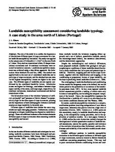
The general term “landslide” is very popular. A cursory Google search of the term landslide has yielded 6,100,000 results. The reason is that the topic of landslides is of inter‑ est to researchers in a wide range of scientific disciplines, which include sedimentology, oceanography, geomor‑ phology, volcanology, seismology, glaciology, areology (i.e., geology of Mars), deep‑sea structural engineering, highway engineering, soil mechanics, climate change, eu‑ stasy, natural hazards, and petroleum exploration and pro‑ duction. Not surprisingly, each scientific community has arrived at its own nomenclatural scheme (Hansen, 1984). However, there is no conceptual link between different schemes on landslides. Consequently, the term landslide means different things to different populace. This concep‑ tual disconnect and its consequences are the primary focus of this paper. Since the early recognition of subaerial “landslides” in 186 BC in China (Li, 1989), their common occurrences in subaerial and submarine environments have been well documented worldwide (Figure 1). In subaerial settings, for example, fault‑induced alluvial fans are dominated by mass‑transport deposits (McPherson et al., 1987). Aspects of subaerial, sublacustrine, and submarine land‑ slides have been reviewed adequately during the past 140 years (Baltzer, 1875; Howe, 1909; Reynolds, 1932; Ladd, 1935; Sharpe, 1938; Ward, 1945; Popov, 1946; Eckel, 1958; Yatsu, 1967; Hutchinson, 1968; Zaruba and Mencl, 1969; Blong, 1973; Crozier, 1973; Coates, 1977; Woodcock, 1979; Hansen, 1984; Varnes, 1984; Brabb and Harrod, 1989; Schwab et al., 1993; Hampton et al., 1996; Elverhøi et al., 1997; Locat and Lee, 2000, 2002; Hungr et al., 2001; Dykstra, 2005; Glade et al., 2005; Solheim et al., 2005a; Masson et al., 2006; Shanmugam, 2009, 2012a, 2013a; Moernaut and De Batist, 2011; Shipp et al., 2011; Clague and Stead, 2012; Krastel et al., 2014, among oth‑ ers). On Earth, landslides have been recognized on bathy‑ metric images (Figure 2) (Greene et al., 2006), on seis‑ mic profiles (Figure 3) (Solheim et al., 2005b) (Gee et al., 2006), in outcrops (Heim, 1882; Macdonald et al., 1993), and in conventional cores (Shanmugam, 2006a, 2012a). On Mars, landslides have been interpreted using shaded‑
relief map of the Thaumasia Plateau (Thermal Emission Imaging System infrared [THEMIS IR]) by Montgomery et al. (2009, their Figure 9).
1.1
Importance of mass-transport deposits (MTD)
Mass‑transport deposits (MTD) are important not only because of their volumetric significance in the sedimen‑ tary record (Gamboa et al., 2010), but also because of their frequent impacts on human lives both socially and economically (USGS, 2010; Petley, 2012). Since the birth of modern deep‑sea exploration by the voyage of H.M.S. Challenger (December 21, 1872-May 24, 1876), organ‑ ized by the Royal Society of London and the Royal Navy (Murray and Renard, 1891), oceanographers have made considerable progress in understanding the world’s oceans. Nevertheless, the physical processes that are responsible for transporting sediment downslope into the deep sea are still poorly understood. This is simply because the physics and hydrodynamics of these processes are difficult to observe and measure directly in deep‑marine and extraterrestrial en‑ vironments. This observational impediment has created an enormous challenge for understanding and communicat‑ ing the mechanics of gravity‑driven downslope processes with clarity. Furthermore, deep‑marine environments are known for their complexity of processes and their depos‑ its, composed not only of mass‑transport deposits but also of bottom‑current reworked deposits (Shanmugam, 2006a, 2012a). Thus a plethora of confusing concepts and clas‑ sifications exists. MTD constitute major geohazards on subaerial environ‑ ments (Geertsema et al., 2009; Glade et al., 2005; Jakob and Hungr, 2005; Kirschbaum et al., 2010). They are ubiq‑ uitous on submarine slopes (Figure 1) and are destructive (Hampton, et al., 1996). Submarine mass movements may bear a tsunamigenic potential and are capable of methane gas release into the seawater and atmosphere (Urgeles et al., 2007). The U.S. Geological Survey (USGS, 2010) has compiled data on worldwide damages caused by large subaerial and submarine MTD in the 20th and 21st centu‑ ries (Table 1). Annual losses associated with MTD have been estimated to be about 1-2 billion dollars in the U.S. alone (Schuster and Highland, 2001). Recently, the Oso landslide, which occurred on March 22, 2014 near Seattle
G. Shanmugam: The landslide problem
Vol. 4 No. 2
150°W
120 °
90 °
60°
30°
0° 30° Jan Mayen Ridge
111
60 °
90°
120°
150° E
7 8 Storegga
Alaska Bering Mt. St. Helens Goleta
Baikal
Frank
Grand Banks Thistle Currituck Canary 3 4 Hatteras Monterey 2 MauritaniaMarkagunt 1 Mississippi Alika East Breaks Vargas Senegal
Nevado del Ruiz Pacific Ocean
Ancash
Santiago Submarine MTD Subaerial MTD Description of core Description of outcrop
Amazon
5
60°N
Elm
6
Kolka 9
Usoy Saidmerah
Nice Nile
Bududa
11 12 Zaire Atlantic Ocean Rio de Janeiro
Kyoto 30°N
Yigong
Aqaba 10
Gansu
13 Owen Ridge
Bassein
Leyte
KG
Indian Ocean
Brunei Kutei
0° Unnamed
Agulhas
30°S
Bass
Rio Colorado Alexander Island Weddell Sea Antarctic Ocean
Ruatoria 60°S
Figure 1 Map showing 50 examples (locations) of submarine (black triangle) and subaerial (white triangle) mass‑transport deposits (MTD) that are often erroneously called “landslides” (see Tables 1, 2, and 5). Submarine and subaerial classification of each MTD denotes its depositional setting. Note locations of core studies (numbered yellow circles) and outcrop studies (numbered red circles) of deep‑water successions carried out by the present author worldwide on MTD and SMTD (see Table 3 for details). 28 Submarine MTD: Bering, Bering Sea (Karl et al., 1996; Nelson et al., 2011); Goleta, U.S. Pacific Margin (Greene et al., 2006); Monterey, U.S. Pacific Margin (Paull et al., 2005); Alika, Hawaii, Pacific (Normark et al., 1993); East Breaks, U.S. Gulf of Mexico (McGregor et al., 1993); Mississippi, U.S. Gulf of Mexico (Weimer, 1989, 1990; McAdoo et al., 2000; Nelson et al., 2011); Grand Banks, North Atlantic, Canada (Heezen and Ewing, 1952; Piper and Aksu, 1987; Bornhold et al., 2003); Currituck, U.S. Atlantic Margin (Locat et al., 2009); Hatteras, U.S. Atlantic Margin (Embley, 1980); Amazon, Equatorial Atlantic (Damuth et al., 1988; Piper et al., 1997); Alexander Island, Antarctica (Macdonald et al., 1993); Weddell Sea, Antarctica (Gales et al., 2014); Jan Mayen Ridge, NorwegianGreenland Sea (Laberg et al., 2014); Storegga, Norwegian Sea (Bugge et al., 1987; Haflidason et al., 2005); Nice, Mediterranean Sea (Dan et al., 2007); Nile, Mediterranean Sea (Newton et al., 2004); Canary, SW off Morocco, North Atlantic (Masson et al., 1997); Mauritania‑Senegal, W Africa, North Atlantic (Jacobi, 1976); Zaire (formerly known as Congo), W Africa, S Atlantic (Shepard and Emery, 1973); Owen Ridge, Oman coast, Indian Ocean (Rodriguez et al., 2013); Agulhas, SE Africa, Indian Ocean (Dingle, 1977); KG (Krishna‑Godavari Basin), Bay of Bengal, NE Indian Ocean (Shanmugam et al., 2009); Bassein, NE Indian Ocean (Moore et al., 1976); Brunei, NW Borneo Margin (Gee et al., 2007); Kutei, Makassar Strait, Indonesia (Jackson, 2004); Unnamed, offshore New South Wales/Queensland, Australia (Clarke et al., 2012); Bass, SE Australia (Mitchell et al., 2007); Ruatoria, Hikurangi Margin, New Zealand (Collot et al., 2001). 22 Subaerial MTD: Alaska, State of Alaska, U.S. (USGS, 2010); Frank, Canada (Cruden and Hungr, 1986); Mt. St. Helens, State of Washington, U.S. (Schuster, 1983; Tilling et al., 1990); Markagunt, State of Utah, U.S. (Hacker et al., 2014); Thistle, State of Utah, U.S. (USGS, 2010); Vargas, Venezuela (USGS, 2010); Nevado del Ruiz, Colombia (Pierson, 1990); Ancash, Peru (USGS, 2010); Santiago, Chile (Sepúlveda et al., 2006); Rio de Janeiro, Brazil (USGS, 2010); Rio Colorado, Argentina (USGS, 2010); Elm, Swiss Alps (Heim, 1882); Aqaba, Gulf of Aqaba (Klinger et al., 1999); Bududa, Uganda (USGS, 2010); Kolka, Russia (North Ossetia) (USGS, 2010); Saidmerah, Iran (Harrison and Falcon, 1938); Usoy, Tajikistan (Bolt et al., 1975; USGS, 2010); Baikal, Olkhon Island (Lake Baikal, Siberia) (Tyszkowski et al. 2014); Gansu, China (USGS, 2010); Yigong, Tibet (USGS, 2010); Kyoto, Japan (USGS, 2010); Leyte, Philippines (USGS, 2010); Blank world map credit: http://upload.wikimedia.org/wikipedia/com‑ mons/8/83/Equirectangular_projection_SW.jpg (accessed December 27, 2014).
(US), killed 43 people (PBS, 2014; Wikipedia, 2014). Dur‑ ing a 7‑year global survey (2004-2010), a total of 2,620 MTD had caused a loss of 32,322 human lives (Petley, 2012). MTD vary in size greatly. The world’s largest subma‑
rine MTD is the Agulhas Slump in SE Africa (Dingle, 1977), which is 20,331 km3 in size (Figure 1, Table 2). This submarine MTD is 10 times volumetrically larger than the world’s largest subaerial MTD (Markagunt grav‑ ity slide, southwest Utah, Figure 1), which is 2,000 km3
112
JOURNAL OF PALAEOGEOGRAPHY
Apr. 2015
A
B
Figure 2 A-Multibeam bathymetric image of the Goleta slide complex in the Santa Barbara Channel, southern California. Note lobe‑like (dashed line) distribution of displaced material that was apparently detached from the main scarp near the shelf edge. This mass transport complex is composed of multiple segments of failed material; B-Sketch of the Goleta mass transport complex in the Santa Barbara Channel, southern California showing three distinct segments (i.e., west, central, and east). Contour intervals (-100, -200, -300, -400, -500, and -600) are in meters. From Greene et al. (2006). Images courtesy of H. G. Greene. Credit: European Geosciences Union.
in size (Table 2). On Mars, MTD of immense dimensions (e.g., 3,000 km wide) have been studied (Montgomery et al., 2009, their Figure 9). Large submarine MTD have im‑ portant implications for developing deep‑water petroleum reservoirs. In fact, many petroleum reservoirs currently produce oil and gas from sandy mass‑transport deposits (SMTD) worldwide (Shanmugam, 2006a, 2012a). Petrole‑ um‑related examples are: (1) the occurrence of submarine landslides in all continental margins that are areas of active petroleum exploration (Mienert et al., 2002, their Figure 1); (2) potential petroleum reservoirs associated with a submarine landslide located off Baltimore Canyon on the U.S. Atlantic margin (Malahoff et al., 1978); (3) the loca‑ tion of the Ormen Lange gas field inside the Storegga Slide scar, offshore Norway (Solheim et al., 2005a; Bryn et al., 2005); (4) petroleum‑producing reservoirs composed of
SMTD and associated sand injections in the North Sea, in‑ cluding the Gryphon Field (Shanmugam et al., 1995; Pur‑ vis et al., 2002; Duranti and Hurst, 2004), Norwegian Sea (Shanmugam et al., 1994), Gulf of Mexico (Shanmugam, 2006a, 2012a), Mexico (Grajales‑Nishimura et al., 2000), Brazil (Shanmugam, 2006a), Nigeria (Shanmugam, 1997), Australia (Meckel, 2010), China (Zou et al., 2012), and the Bay of Bengal, India (Shanmugam et al., 2009); (5) the use of 3‑D seismic data in predicting reservoir properties of submarine landslides in the Saguenay Fjord, Canada (Hart et al., 2001); (6) reservoir characterization of SMTD (Meckel, 2011); and (7) hydrocarbon traps associated with MTD (Beaubouef and Abreu, 2010; Alves and Cartwright, 2010). Furthermore, MTD form a significant component of deep‑water stratigraphy in the Espírito Santo Basin, SE Brazil, where MTD constitute more than 50% of Eocene‑
G. Shanmugam: The landslide problem
Vol. 4 No. 2
113
Figure 3 Seismic profile showing transparent (homogeneous) to chaotic internal reflections of slide deposits (SD). Note continuous and parallel internal reflections of contourite deposits (CD). The Storegga Slide on the mid-Norwegian continental margin. TNU=Local slip plane. Profile courtesy of A. Solheim. Modified after Solheim et al. (2005b). With permission from Elsevier Copyright Clearance Center’s RightsLink: Licensee: G. Shanmugam. License Number: 3570801423159. License Date: February 16, 2015. Table 1 Worldwide large subaerial and submarine mass‑transport deposits (MTD), their sizes (volume), triggering mechanisms, and damages in the 20th and 21st Centuries. The term “landslide” was originally used to describe these examples. Modified after USGS (2010). Year
Location
Name and type
Triggering mechanism Usoy earthquake, magnitude 7.4
Size, damage, and loss of human life 2,000,000,000 m3 54 deaths
1911 Tajikistan
Usoy MTD
1914 Argentina
Rio Barrancas and Failure of ancient MTD Rio Colorado debris flow dam
2,000,000 m3 Length of flow: 300 km
1919 Indonesia (Java)
Kelut MTD
Eruption of Kelut Volcano
185 km (length) Lahars caused 5,110 deaths, and destroyed or damaged 104 villages
Loess flows, MTD
Haiyuan earthquake, mag‑ nitude 8.5
50,000 km2 (area) 100,000+ deaths
1920 Mexico
Rio Huitzilapan debris flows
Earthquake, magnitude 6.5-7.0
>40 km (length) 600-870 deaths
1921 Kazakh Republic
Alma-Ata debris flow
Snow melt, subsequent rainfall
500 deaths
Deixi MTD
Deixi earthquake, magnitude 7.5
>150,000,000 m3 2,500 deaths
1920
1933
China (Gansu), Haiyuan
China (Sichuan)
JOURNAL OF PALAEOGEOGRAPHY
114
Apr. 2015 Table 1, continued
Year
Location
Triggering mechanism
Size, damage, and loss of human life
Mount Rokko MTD
Rainfall
505 deaths or missing, 130,000 homes were destroyed or badly damaged.
1941 Peru
Huaraz debris flow
Failure of moraine dam
10,000,000 m3 4,000-6,000 deaths
1945 Peru
Cerro Condor‑Sencca MTD
Erosional under‑cutting
5,500,000 m3 13 bridges were destroyed.
1938
Japan (Hyogo)
Name and type
1949
Tajikistan Khait MTD (Tien Shan Mtns.)
Khait earthquake, magnitude 7.4
245,000,000 m3 7,200 deaths
1953
Japan (Wakayama)
Arida River MTD
Rainfall Major typhoon (cyclone)
1,046 deaths
1953
Japan (City of Kyoto)
Arida River MTD
Rainfall
336 deaths 5,122 homes were destroyed.
1958
Japan (Shizuoka)
Kanogawa MTD
Rainfall
1,094 deaths 19,754 homes were destroyed.
Rupanco region MTD
Valdivia earthquake, magnitude 7.5, preceded by heavy rain
40,000,000 m3 210 deaths
1960 Chile
1962
Peru (Ancash)
1963
Italy (Friuli-Ven‑ Vaoint Reservoir MTD ezia Griulia)
Nevados Huascaran MTD Not known
13,000,000 m3 4,000-5,000 deaths
Not known
250,000,000 m3 2,000 deaths
Alaska earthquake, magnitude 9.0
211,000,000 m3 submarine lMTD at Seward; Turnagain Heights MTD, 9,600,000 m3 Loss: $280,000,000 (1964 dollars); 122 deaths
1964
United States (Alaska)
Alaska earthquake MTD (also known as “Prince William Sound earth‑ quake”)
1965
China (Yunnan)
MTD
Not known
450,000,000 m3 444 deaths.
1966
Brazil (Rio de Janeiro)
MTD
Rainfall
1,000 deaths
1970
Peru (Ancash)
Nevados Huascaran MTD Earthquake, magnitude 7.7
30,000,000-50,000,000 m3 18,000 deaths
1974 Peru
Mayunmarca MTD
Rainfall
1,600,000,000 m3 450 deaths
1976 Guatemala
Guatemala earthquake MTD
Guatemala earthquake, magnitude 7.5
10,000 MTDs over an area of 16,000 km2 200 deaths
Mining activity‑occurred on man‑made layered slopes
150,000,000 m3 284 deaths
Eruption of Mount St. Helens volcano
This is the world’s largest historical MTD. 3,700,000,000 m3 250 homes, 47 bridges, 24 km of rail, and 298 km of highway were destroyed; 57 deaths.
Snow melt and subsequent rainfall
21,000,000 m3 ; This is the most expensive disaster to fix in U.S. history with a loss of $600,000,000 (1983 dollars).
1980
China Yanchihe MTD (Yichang, Hubei)
United States 1980 (Washington)
1983
United States (Utah)
Mount St. Helens MTD
Thistle MTD
G. Shanmugam: The landslide problem
Vol. 4 No. 2
115 Table 1, continued
Year
Location
Name and type
Triggering mechanism
Size, damage, and loss of human life
China (Gansu)
Saleshan MTD
Rainfall
35,000,000 m3 237 deaths
1983 Ecuador
Chunchi MTD
Rain and/or snow (wettest year of century)
1,000,000 m3 150 deaths
1983
1985
Colombia (Tolima)
Nevado del Ruiz debris flows
Eruption of Nevado del Ruiz volcano
23,000 deaths
1985
Puerto Rico (Mameyes)
MTD
Rainfall from tropical storm
129 deaths
Bairaman MTD
Bairaman earthquake, magnitude 7.1
200,000,000 m3
Reventador MTD
Reventador earthquakes, magnitude 6.1 and 6.9 and rainfall
75,000,000-110,000,000 m3 1,000 deaths
1987 Venezuela
Rio Limon, debris flow
Rainfall
2,000,000 m3 210 deaths
1987 Colombia
Villa Tina MTD
Pond leakage
20,000,000 m3 217 deaths
1988 Brazil
Rio de Janeiro and Pe‑ tropolis MTD
Rainfall
Approximately 300 deaths
China 1989 (Huaying, Si‑ chuan)
Xikou MTD
Rainfall
221 deaths
China 1991 (Zhaotong, Yunan)
Touzhai MTD
Rainfall
18,000,000 m3 216 deaths
1991 Chile
Antofagasta debris flows
Rainfall
500,000,000-700,000,000 m3 “Hundreds” of deaths were reported.
1993 Ecuador
La Josefina MTD
Mine excavation and heavy 20,000,000-25,000,000 m3 13 bridges destroyed rainfall
Paez MTD
Paez earthquake, magni‑ tude 6.0
250 km2 (area) 272 deaths
Rainfall
221 deaths
MTD
Rainfall
More than 100 individual slope failures
Honduras, Guate‑ 1998 mala, Nicaragua, MTD El Salvador
Rainfall
Hurricane Mitch caused torrential rainfall. Ap‑ proximately 10,000 deaths
Venezuela 1999 (Vargas, northern coastal area)
MTD
Rainfall
Nearly 1m of heavy rain fall in a 3‑day period. There were as many as 30,000 deaths. Loss: $1,900,000,000 in 2001 U.S. dollars
1999 Taiwan
MTD
Chi-Chi earthquake, mag‑ 11,000 km2 (area) 158 deaths nitude 7.3
2000 Tibet
Yigong MTD
Meltwater from snow and glacier
Papua, New 1986 Guinea (East New Britain) 1987
1994
Ecuador (Napo)
Colombia (Cauca)
Northern India 1998 (Malpa Himalaya Large MTD Region) 1998
Italy (Campania)
100,000,000 m3 109 deaths
JOURNAL OF PALAEOGEOGRAPHY
116
Apr. 2015 Table 1, continued
Year
Location
Name and type
Triggering mechanism
Size, damage, and loss of human life The January earthquake caused MTD over a 25,000 km2 area, (including parts of Guate‑ mala). The February earthquake caused MTD over a 2,500 km2 area. ~585 deaths
2001 El Salvador
MTD, lateral spreading, liquefaction
2 earthquakes; 1/13/2001: magnitude 7.7 2/13/2001: magnitude 6.6
Russia 2002 (North Ossetia)
Kolka Glacier debris flows
Detachment of large gla‑ cier, causing a debris flow
Travel distance: 19.5 km; 110,000,000 m3 volume of glacial ice deposited 2,000,000-5,000,000 m3 of ice debris at end of runout; 125 deaths
Sri Lanka 2003 (Ratnapura and Hambantota)
MTD
Rainfall
24,000 homes and schools destroyed, 260 deaths
Rainfall
>1,000,000 m3 (total volume) 16 deaths
United States 2003 (San Bernardino Debris flows County, California) 2005
Pakistan and India
MTD
Kashmir earthquake, magnitude 7.6
Thousands of MTD 25,500 deaths
2006
Philippines (Leyte)
MTD
Rainfall
15,000,000 m3 1,100 deaths
2008
China (Sichuan)
MTD
Wenchuan earthquake, magnitude 8.0
15,000 MTD, and 20,000 deaths Still being assessed
Al-Duwayqa MTD
Affected area was 6,500 m3 volume and rocks Destabilization due to man‑ weighed about 18,000 tons. made construction 107 deaths
Egypt 2008 (East Cairo)
2010
Uganda (Bududa)
Debris flows
Heavy rainfall
400+ deaths Still being assessed
2010
Brazil (Rio De Janeiro)
Debris flows
Heavy rainfall
350 deaths Still being assessed
Table 2 Comparison of large‑volume (> 100 km3) mass‑transport deposits (MTD) in submarine environments with four of the largest MTD in subaerial environments. Note that the world’s largest submarine MTD (20,331 km3) is 10 times volumetrically larger than the world’s largest subaerial MTD (2000 km3). The term “landslide” was used to describe many of these examples by the original authors. Locations of selected examples are shown in Figure 1. Compiled from several sources. MTD (Reference)
Volume in km3
Environment (Age)
Comments
1. Agulhas slump SE African margin (Dingle, 1977)
20,331
Submarine (Post‑Pliocene)
The world’s largest submarine MTD trig‑ gered by earthquakes
2. Chamais slump SE African margin (Dingle, 1980)
17,433
Submarine (Neogene)
Triggered by earthquakes
3. Nuuanu debris avalanche, NE Oahu, Hawaii (Normark et al., 1993; Moore et al., 1994)
5000
Triggered by volcanic activity; Debris Submarine avalanche is a velocity‑based term (see (2.7 Ma, Ward, 2001) text).
4. Storegga slide Offshore Norway (Bugge et al., 1987; Haflidason et al., 2005)
2400-3200
Submarine (8100 yrs BP)
Triggered by earthquakes
G. Shanmugam: The landslide problem
Vol. 4 No. 2
117 Table 2, continued
MTD (Reference)
Volume in km3
Environment (Age)
Comments
5. WMTD, Amazon fan Equatorial Atlantic (Piper et al., 1997)
2000
Submarine (Late Pleistocene)
WMTD: Western mass‑transport deposits. Possibly triggered during falling sea level (Damuth et al., 1988)
6. Insular slope slide Puerto Rico (Schwab et al., 1993)
1500
Submarine (Quaternary?)
Triggered by earthquakes
7. Brunei slide NW Borneo (Gee et al., 2007)
1200
Submarine (Quaternary?)
Triggered by sediment loading, gas hy‑ drates, and earthquakes
8. Saharan debris flow NW African Margin (Embley, 1976; Embley and Jacobi, 1977; Gee et al., 1999)
600-1100
Submarine (60,000 yrs BP)
Long-runout volcaniclastic debris flows of over 400 km on gentle slopes that decrease to as little as 0.05º
9. Orotava-Icod-Tino debris avalanche, NW African slope (Wynn et al., 2000)
1000
Submarine (Pleistocene)
Debris avalanche is a velocity‑based term (see text).
10. Slump complex, Israel (Frey‑Martinez et al., 2005)
1000
Submarine (Plio-Quaternary)
Triggered by earthquakes
11. Bassein slide Sunda Arc, NE Indian Ocean (Moore et al., 1976)
900
Submarine (Late Quaternary)
Triggered by earthquakes
12. Alika 1 and 2 debris avalanches, NE Oahu, Hawaii (Normark et al., 1993)
200-800
Submarine (300,000-105,000 yrs BP))
Triggered by volcanic activity; Debris avalanche is a velocity‑based term (see text).
13. Nile MTC offshore Egypt (Newton et al., 2004)
670
Submarine (Quaternary)
MTC = Mass-transport complex; triggered by rapid sedimentation
14. Copper River slide Kayak Trough Northern Gulf of Alaska (Carlson and Molnia, 1977)
590
Submarine (Holocene)
Possibly triggered by earthquakes and rapid sedimentation
15. MTC 1, Trinidad (Moscardelli et al., 2006)
242
Submarine (Plio-Pleistocene)
MTC 1 = Mass-transport complex 1; triggered by tectonic activity and rapid sedimentation
16. Cape Fear MTD The Carolina Trough U.S. Atlantic Margin (Popenoe et al., 1993; Lee, 2009)
200
Submarine (Pleistocene)
Triggered by salt tectonism and gas hy‑ drate decomposition
17. The 1929 Grand Banks MTD, off the U.S. Atlantic coast and Canada (Heezen and Ew‑ 185-200 ing, 1952; Piper and Aksu, 1987; Driscoll et al., 2000; Bornhold et al., 2003)
Submarine (1929)
Triggered by earthquakes, magnitude 7.2
18. Currituck slide U.S. Atlantic Margin (Locat et al., 2009)
Submarine (24-50 ka)
Triggered by earthquakes and high pore pressure
Submarine (15-20 ka)
Possibly triggered by salt tectonism
165
19. East Breaks slide (western lobe) NW Gulf of Mexico ~160 (McGregor et al., 1993)
JOURNAL OF PALAEOGEOGRAPHY
118
Apr. 2015 Table 2, continued
MTD (Reference)
Volume in km3
Environment (Age)
Comments
20. MTD, Mississippi Canyon area Gulf of Mexico (McAdoo et al., 2000)
152
Submarine (Holocene)
Triggered by salt tectonism and rapid sedimentation
21. Jan Mayen Ridge Norwegian-Greenland Sea (Laberg et al., 2014)
60
Submarine (Pliocene and Pleis‑ tocene)
Retrogressive movement
22. Owen Ridge Oman coast, Arabian Sea (Rodriguez et al., 2013)
40
Submarine (Holocene)
Retrogressive slumps
23. Markagunt gravity slide, SW Utah (USA) 1700-2000 (Hacker et al., 2014)
Subaerial 21-22 Ma
The world’s largest prehistoric subaerial volcanic MTD
24. Saidmarreh Slide Kabir Kuh anticline, SW Iran (Harrison and Falcon, 1938)
20
Subaerial (10,370+/-120 years The world’s second largest prehistoric BP, Shoaei and Ghay‑ subaerial MTD triggered by earthquakes oumian, 1998)
25. Mount St. Helens, USA (Schuster, 1983; Tilling et al., 1990)
2.8
Subaerial (May 18, 1980)
The world’s largest historic subaerial MTD triggered by volcanic eruption (USGS, 2004)
26. Usoy, Tadzhik Republic (Formerly USSR) (Bolt et al., 1975)
2.0
Subaerial (1911)
The world’s second largest historic subae‑ rial MTD triggered by earthquakes, magnitude = 7.4 (USGS, 2010)
Oligocene strata (Gamboa et al., 2010). Because the petro‑ leum industry is moving exploration increasingly into the deep‑marine realm to meet the growing demand for oil and gas, a clear understanding of deep‑marine MTD is of great economic interest. For this reason, detailed descriptions of 7,832 meters of conventional cores from 123 wells, repre‑ senting 32 petroleum fields worldwide (Table 3), provide the empirical data in this review.
1.2
Description of the problem
The basic problem stems from our failure to follow a sound and commonly applied concept for classifying MTD. In acknowledging this chronic problem, Camer‑ lenghi et al. (2010, p. 506) state, “For typology, we selected the following terms according to the terminology in the original manuscripts: Debris Avalanche; debris flow; deep-seated failure (when recognized mainly in deep penetration seismic profiles rather than bathymetric maps); glide; gravitational collapse; mass failure; mass transport; mass wasting; megaturbidite; slide; slump. Such terms often describe similar deposits. For the time being we have not modified the terminology. It is obvious that a unified terminology is needed for correct understanding and comparison of sedimentary deposits originated from sub-
marine sediment mass transport.” There is absolutely no sedimentological basis for equating large turbidites (i.e., megaturbidites) with slumps, slides, or debris avalanches. The current complacent usage of superfluous nomencla‑ ture is not only confusing but unnecessary. Clearly, there is a need for conceptual clarity, which is one of the objectives of this article. The conceptual and nomenclatural problems are not unique to MTD. Similar problems are associated with tur‑ bidites (Sanders, 1965; Shanmugam, 1996) and tsunamites (Shanmugam, 2006b). What is troubling is that the prob‑ lems of MTD are tightly intertwined with those of turbid‑ ites and tsunamites. This conceptual interconnection has led to a long lexicon of 79 types of MTD, which include normal turbidites, high‑density turbidites, seismoturbid‑ ites, megaturbidites, fluxoturbidites, atypical turbidites, and tsuamites (Table 4). Since the first use of the term “landslide” by James Dwight Dana in 1838 (Cruden, 2003), it has been adopted for a number of different downslope mass‑transport pro‑ cesses that operate not only in subaerial (Shreve, 1968; Coates, 1977; Cruden, 1991; Highland and Bobrowsky, 2008), sublacustrine (Moernaut and De Batist, 2011), and submarine (Prior and Coleman, 1979; Schwab et al., 1993;
Vol. 4 No. 2
G. Shanmugam: The landslide problem
119
Table 3 Summary of deep‑water case studies, based on description of core and outcrop, carried out by the present author on MTD and SMTD (1974-2011). Note that most SMTD examples are petroleum‑bearing deep‑water reservoirs. Modified after Shanmugam (2014b). Location symbol and number in Figure 1
Case studies
Thickness of core and outcrop described*
Comments (This paper)
1. Mississippi fan, Quaternary, DSDP Leg 96
~ 500 m DSDP core (selected intervals described)
Mass‑transport deposits, turbidites, bottom‑current reworked sands
2. Green Canyon, Late Pliocene, 3. Garden Banks, Middle Pleistocene 4. Ewing Bank 826, Pliocene-Pleistocene 5. South Marsh Island, Late Pliocene 6. South Timbalier, Middle Pleistocene 7. High Island, Late Pliocene 8. East Breaks, Late Pliocene-Holocene
1067 m Conventional core and piston core 25 wells
Sandy mass‑transport de‑ posits and bottom‑current reworked sands common
2. California 9. Midway Sunset Field, upper Miocene, (Shanmugam and Clayton, 1989; onshore Shanmugam, 2006a, 2012a)
650 m Conventional core 3 wells
Sandy mass‑transport de‑ posits and bottom‑current reworked sands
3. Ouachita Mountains, Arkansas and Oklahoma, U.S. (Shan‑ 10. Jackfork Group, Pennsylvanian mugam and Moiola, 1995)
369 m 2 outcrop sections
Sandy mass‑transport de‑ posits and bottom‑current reworked sands common
4. Southern Appalachians, Ten‑ nessee, U.S. (Shanmugam, 1978; 11. Sevier Basin, Middle Ordovician Shanmugam and Benedict, 1978)
2152 m 5 outcrop sections
Mass‑transport deposits, turbidites, bottom‑current reworked sands
5. Brazil (Shanmugam, 2006a, 2012a)
12. Lagoa Parda Field, lower Eocene, Espirito Santo Basin, onshore 13. Fazenda Alegre Field, upper Cretaceous, Espirito Santo Basin, onshore 14. Cangoa Field, upper Eocene, Espirito Santo Basin, offshore 200 m 15. Peroá Field, lower Eocene to upper Oligo‑ Conventional core cene, Espirito Santo Basin, offshore 10 wells 16. Marlim Field, Oligocene, Campos Basin, offshore 17. Marimba Field, upper Cretaceous, Cam‑ pos Basin, offshore 18. Roncador Field, upper Cretaceous, Cam‑ pos Basin, offshore
Sandy mass‑transport de‑ posits and bottom‑current reworked sands common
6. North Sea (Shanmugam et al., 1995)
19. Frigg Field, lower Eocene, Norwegian North Sea 20. Harding Field (formerly Forth Field), lower Eocene, U.K. North Sea 3658 m 21. Alba Field, Eocene, U.K. North Sea Conventional core 22. Fyne Field, Eocene, U.K. North Sea 50 wells 23. Gannet Field, Paleocene, U.K. North Sea 24. Andrew Field, Paleocene, U.K. North Sea 25. Gryphon Field, upper Paleocene-lower Eocene, U.K. North Sea
Sandy mass‑transport de‑ posits and bottom‑current reworked sands common
7. U.K. Atlantic Margin (Shanmugam et al., 1995)
26. Faeroe area, Paleocene, west of the Shet‑ land Islands 27. Foinaven Field, Paleocene, west of the Shetland Islands
1. Gulf of Mexico, U.S. (Shanmugam et al., 1988b)
1. Gulf of Mexico, U.S. (Shanmugam et al., 1993a, 1993b; Shanmugam and Zim‑ brick, 1996)
Thickness included in the North Sea count Sandy mass‑transport de‑ 1 well posits and bottom‑current Conventional core reworked sands common 1 well
JOURNAL OF PALAEOGEOGRAPHY
120
Apr. 2015 Table 3, continued
Location symbol and number in Figure 1
8. Norwegian Sea and vicinity (Shanmugam et al., 1994)
9. French Maritime Alps, south‑ eastern France (Shanmugam, 2002, 2003) 10. Nigeria (Shanmugam, 1997, 2006a, 2012a)
Thickness of core and outcrop described*
Case studies
Comments (This paper)
28. Mid‑Norway region, Cretaceous, Norwe‑ gian Sea 29. Agat region, Cretaceous, Norwegian North Sea
500 m Conventional core 14 wells
Sandy mass‑transport de‑ posits and bottom‑current reworked sands common
30. Annot Sandstone, Eocene-Oligocene
610 m** 1 outcrop section (12 units described)
Sandy mass‑transport de‑ posits and bottom‑current reworked sands common (deep tidal currents)
31. Edop Field, Pliocene, offshore
875 m Conventional core 6 wells
Sandy mass‑transport de‑ posits and bottom‑current reworked sands common (deep tidal currents)
294 m Conventional core 2 wells
Sandy mass‑transport de‑ posits and bottom‑current reworked sands common
11. Equatorial Guinea (Famakinwa et al., 1996; ; Shan‑ 32. Zafiro Field, Pliocene, offshore 33. Opalo Field, Pliocene, offshore mugam, 2006a, 2012b) 12. Gabon (Shanmugam, 2006a, 2012a)
34. Melania Formation, lower Cretaceous, offshore (includes four fields)
275 m Conventional core 8 wells
Sandy mass‑transport de‑ posits and bottom‑current reworked sands common
13. Bay of Bengal, India (Shanmugam et al., 2009)
35. Krishna-Godavari Basin, Pliocene
313 m Conventional core 3 wells
Sandy debrites and tida‑ lites common
Kutei Basin, Miocene
2 wells? (Saller et al., 2006, 2008a, 2008b)
Discussion of problematic turbidites (Shanmugam, 2008a, 2013c, 2014a)
Kutei Basin , Makassar Strait (Saller et al., 2006)
Total thickness of rocks described by the author
11,463 m
* The rock description of 35 case studies of deep‑water systems comprises 32 petroleum‑producing massive sands worldwide. De‑ scription of core and outcrop was carried out at a scale of 1:20 to 1:50, totaling 11,463 m, during 1974-2011, by G. Shanmugam as a Ph.D. student (1974-1978), as an employee of Mobil Oil Corporation (1978-2000), and as a consultant (2000-2011). Global studies of cores and outcrops include a total of 7832 meters of conventional cores from 123 wells, representing 32 petroleum fields worldwide (Shanmugam, 2013d).These modern and ancient deep‑water systems include both marine and lacustrine settings. ** The Peira Cava outcrop section was originally described by Bouma (1962), and later by Pickering and Hilton (1988, their Figure 62), among others.
Table 4 Nomenclature of 79 different types of mass‑transport processes and their deposits with overlapping and confusing meanings. Compiled from several sources. Updated after Shanmugam (2012a). Nomenclature
Characteristics
Reference
Comments
1. Landslide: Type 1 (First classification by J. D. Dana in 1862) (see Cruden, 2003)
Refers to three processes: rock slides, earth spreads, and debris flows
Cruden (2003)
Impractical * (MTD or SMTD)**
2. Landslide: Type 2 (GSA Thematic Volume)
A general term used for various moderately rapid gravity‑induced mass movements, which exclude creep and solifluction
Coates (1977)
Impractical (MTD or SMTD)
3. Landslide: Type 3 (AGI Glossary)
A general term for a variety of gravity‑induced downslope mass movements, which include creep and solifluction
Bates and Jackson (1980)
Impractical (MTD or SMTD)
Vol. 4 No. 2
G. Shanmugam: The landslide problem
121 Table 4, continued
Nomenclature
Characteristics
Comments
Reference
4. Landslide: Type 4 (NATO Workshop)
A sudden movement of earth and rocks down a steep slope
5. Landslide: Type 5 (USGS Handbook)
A downslope movement of rock or soil, or both, occurring on the surface of rupture in which Highland and Bobrowsky Impractical much of the material often moves as a coher‑ (2008) (MTD or SMTD) ent or semi‑coherent mass with little internal (See also Eckel, 1958) deformation
6. Fall or rockfall
Freefall of material from steep slopes
Varnes (1978)
Impractical (MTD or SMTD)
7. Sand fall
Freefall of material at submarine canyon heads
Shepard and Dill (1966)
Impractical (SMTD)
8. Topple
Tilting without collapse
Varnes (1978)
Impractical (MTD or SMTD)
9. Slide
Coherent mass with translational movement
Dott (1963)
Slide
10. Slump
Coherent mass with rotational movement and internal deformation
Dott (1963)
Slump
11. Translational slump
Translational movement
Milia et al. (2006)
Translational movements associated with slides (Dott., 1963), MTD
12. Drained slump
Slumping without excess pore pressure
Morgenstern (1967)
Impractical (MTD)
13. Undrained slump
Slumping with excess pore pressure
Morgenstern (1967)
Impractical (MTD)
Reiche (1937)
Impractical (MTD or SMTD)
14. Toreva‑block (Named after the village of Backward rotational slip Toreva in Arizona, USA)
Saxov (1982) (See also Cruden, 1991)
Impractical (MTD or SMTD)
15. Spread
Lateral extension accommodated by shear or tensile fractures
Varnes (1978)
Impractical (MTD or SMTD)
16. Debris flow
Plastic (en masse) flow with laminar state
Dott (1963), Hampton (1972)
Debrite
17. Debris avalanche
Extremely fast-moving debris flows
Varnes (1978)
Impractical (MTD or SMTD)
18. Cohesionless debris avalanche
Rolling, cascading, and collision of rock frag‑ ments on steep underwater slopes
Prior and Bornhold (1990)
Impractical (SMTD)
19. Rock-fragment flow
Large extremely rapid “rock fall-debris flows”
Varnes (1958, 1978)
Impractical (MTD)
20. Debris slide
Slow‑moving mass that breaks up into smaller blocks
Varnes (1978)
Impractical (MTD or SMTD)
21. Flow slide (two words)
Disintegrating subaerial slide in coarse material Koppejan et al. (1948) where a temporary transfer of part of the normal (see also Rouse, 1984) stress onto the fluids of the void space, with a consequent sudden decrease in strength
Impractical (MTD or SMTD)
22. Flow slide (two words)
High‑velocity, transitional type between slumps Shreve ( 1968) and debris lows
Impractical (MTD or SMTD)
23. Flowslide (one word)
Basal dense layer with viscoplastic behavior in stratified submarine sediment flows
SMTD and associated turbidite
Norem et al. (1990)
JOURNAL OF PALAEOGEOGRAPHY
122
Apr. 2015 Table 4, continued
Nomenclature
Characteristics
Comments
Reference
24. Marine flow slide
Liquefied marine sand with high porosity and high pore‑water pressure
25. Retrogressive flow slide
Occurring along banks of noncohesive clean Andresen and Bjerrum sand or silt and showing repeated fluctuations in (1967) porewater pressure
26. Deep creep
Slow moving mass of bedrock (Synonym: rock flow)
Varnes (1978, his Figure 2.2)
Impractical (MTD or SMTD)
27. Soil creep
Slow moving mass of fine soil
Varnes (1978, his Figure 2.2)
Impractical (MTD or SMTD)
28. Seasonal creep
Slow moving mass within the soil horizon af‑ fected by seasonal changes in soil moisture and temperature
Hansen (1984)
Impractical (MTD or SMTD)
29. Continuous creep
Slow moving mass where shear sress continu‑ ously exceeds the material strength
Hansen (1984) (USGS, 2004)
Impractical (MTD or SMTD)
30. Progressive creep
Slow moving mass associated with slopes reaching point of failure by other mass move‑ ments
Hansen (1984)
Impractical (MTD or SMTD)
31. Talus creep
Slow moving large angular rock fragments on a gentle slope Sharpe (1938) (Synonym: scree creep)
Impractical (MTD or SMTD)
32. Slump‑creep
Slow moving multiple processes
33. Mass creep
Slow moving submarine slope sediments due to Almagor and Wiseman repeated loading effects by earthquakes (1982)
Impractical (MTD or SMTD)
34. Rock‑glacier creep
Slow moving tongue of the rock glacier
Sharpe (1938)
Impractical (MTD or SMTD)
35. Solifluction Slow moving waterlogged soil over permafrost (Soil flow of Varnes, 1978) layers
Anderson (1906)
Impractical (MTD)
36. Earth flows
Slow-to fast-moving fine soil
Varnes (1978)
Impractical (MTD)
37. Sturzstrom (Synonym: rock ava‑ lanche)
Fast-moving debris flows
Hsü (1975, 2004)
Impractical (MTD or SMTD)
38. Inertia flow
Grain avalanching
Bagnold (1954)
SMTD
39. Grain flow
Sediment support by grain collision
Middleton and Hampton (1973)
SMTD
40. Fluidized flow
Full sediment support by upward intergranular flow
Middleton and Hampton (1973)
Impractical (SMTD)
41. Liquefied flow
Partial sediment support by upward intergranu‑ lar flow
Lowe (1976)
Impractical (SMTD)
42. Turbidity current
Sediment support by fluid turbulence
Middleton and Hampton (1973)
Turbidite, not MTD
43. Sand flow
A flow of wet sand that is subjected to fluctua‑ tions in pore‑water pressure
Varnes (1958)
Impractical (SMTD)
44. Loess flow
Intermediate stage between “liquefaction flow” and “sand flow” with increasing grain size
Coates (1977)
Impractical (MTD)
Koning (1982)
Carter and Lindqvist (1975)
Impractical (SMTD) Impractical (SMTD)
Impractical (MTD or SMTD)
Vol. 4 No. 2
G. Shanmugam: The landslide problem
123 Table 4, continued
Nomenclature
Characteristics
45. “High‑density turbidity Stratified lower debris flow and upper turbidity current” current
Comments
Reference Kuenen (1951)
Debrite and turbidite (Shanmugam, 1996)
Shanmugam (1996)
Sandy debrite
47. Cohesionless liquefied Sliding‑related sandy mass flows sandflow
Nemec (1990, his Figure 32)
Impractical SMTD
48. Hyperconcentrated flow
Sediment concentration: 20-60 by volume %
Pierson and Costa (1987)
Impractical SMTD
49. Slurry flow
Cohesive debris flows
Carter (1975a)
Impractical MTD
50. Slurry flow
Synonym for “High‑density turbidity current”
Lowe and Guy (2000)
Impractical MTD or SMTD
51. Lahar
Volcaniclastic debris flow
Bates and Jackson (1980) MTD or SMTD
52. Nuée ardente
Decoupling of pyroclastic flows (i.e., stratified flows)
Fisher (1995)
Impractical MTD
Gaudin et al. (2006)
Impractical (SMTD)
46. Sandy debris flow
Sandy flow with plastic rheology and laminar state
53. Cascading dense water Analogous to “sand fall” of event Shepard and Dill (1966) 54. Dense flow
Basal high‑concentration layer in stratified sedi‑ Norem et al. (1990) ment flows
SMTD and associated turbidite
55. Fluidized cohesion‑ less-particle flow
Basal high‑concentration layer in stratified sedi‑ Friedman et al. (1992) ment flows
SMTD and associated turbidite
56. Liquefied cohesionless Basal high‑concentration layer in stratified sedi‑ Sanders and Friedman coarse-particle flow ment flows (1997)
SMTD and associated turbidite
57. Slide
Basal high‑concentration layer in stratified sedi‑ Kuenen (1951) ment flows
Impractical MTD or SMTD
58. Flowing‑grain layer
Basal high‑concentration layer in stratified sedi‑ Sanders (1965) ment flows
SMTD and associated turbidite
59. Laminar inertia-flow
Basal high‑concentration layer in stratified sedi‑ Postma et al. (1988) ment flows
SMTD and associated turbidite
60. Laminar sheared layer
Basal high‑concentration layer in stratified sedi‑ Vrolijk and Southard (1997) ment flows
SMTD and associated turbidite
61. Traction carpet
Basal high‑concentration layer in stratified sedi‑ Dzulynski and Sanders ment flows (1962)
SMTD and associated turbidite
62. Avalanching flow
Basal high‑concentration layer in stratified sedi‑ Sanders (1965) ment flows
SMTD and associated turbidite
63. Mass flow
Basal high‑concentration layer in stratified sedi‑ Friedman et al. (1992) ment flows
SMTD and associated turbidite
64. Mass flow
Plastic flow with shear stress distributed throughout the mass
MTD or SMTD
65. Laminar mass flow
Gradational processes involving sand flows, Carter (1975b) slumping, sliding, and spontaneous liquefaction
SMTD
66. Granular mass flow
Concentrated grain (> 0.06 mm)‑fluid mixtures in rock avalanches, debris flows, and pyroclas‑ tic flows
Impractical SMTD
Nardin et al., (1979)
Iverson and Vallance (2001)
JOURNAL OF PALAEOGEOGRAPHY
124
Apr. 2015 Table 4, continued
Nomenclature
Characteristics
Reference
Comments
67. Hyperpycnal flow
Sinking river water that has higher density than basin water
Bates (1953), Mulder et al. (2003)
Impractical MTD
68. Dense flow
Multiple processes
Gani (2004)
SMTD and associated turbidite
69. Hybrid flow
Multiple processes
Houghton et al. (2009)
SMTD and associated turbidite
70. Tsunamite (deposit)
“Rope‑ladder texture” and multiple processes
Michalik (1997)
Impractical Shanmugam (2006b)
71. Homogenite Uniform texture, considered (deposit, Kastens and Cita, synonymous with submarine landslide and 1981) megaturbidite
Camerlenghi et al. (2010)
Turbidite, not MTD (Shanmugam, 2006b)
72. Olistostrome (deposit)
Submarine gravity sliding or slumping
Flores (1955); Hsü (1974)
Impractical (MTD or SMTD)
73. Gravitite (deposit)
Debris flows
Natland (1967)
Impractical (MTD or SMTD)
74. Gravite (deposit)
Slide, slump, debris flow, dense flow, and turbidity current
Gani (2004)
Impractical (MTD or SMTD)
75. Fluxoturbidite (deposit) (See Hsü, 2004 for a critique of this term)
Sand avalanche
Dzulynski et al. 1959
Impractical (SMTD)
76. Seismoturbidite (deposit)
Large‑scale mass flows
Mutti et al. (1984)
Impractical (SMTD)
77. Megaturbidite (deposit)
Large‑scale debris flows
Labaume et al. (1987)
Impractical (SMTD)
78. Atypical turbidite (deposit)
Slumps, debris flows, and sand flows
Stanley et al. (1978)
Impractical (SMTD)
79. Duplex‑like structures (deposit)
Slumps and debris flows
Shanmugam et al. (1988a)
Impractical (MTD)
* In some cases, it is impractical to interpret a specific process from the rock record. In such cases, a non-specific term of MTD or SMTD is preferred. **MTD = Mass-transport deposits. SMTD = Sandy mass-transport deposits.
Hampton et al., 1996; Locat and Lee, 2000, 2002; Masson et al., 2006; Feeley, 2007; Twichell et al., 2009) environ‑ ments on Earth, but also in extraterrestrial environments on Venus (Malin, 1992), Mars (Lucchitta, 1979; McEwen, 1989; Montgomery et al., 2009), and Saturn’s satellite Iapetus (Singer et al., 2012), among others. At present, the literal meaning of the word landslide is totally lost in the geologic and engineering literature. For example, (1) Hungr (1995, p. 610) states, “…rapid landslides such as debris flows, debris avalanches, rock slide avalanches, large scale liquefaction failures, and slides…” in de‑ scribing subaerial mass‑transport processes. (2) Twichell et al. (2009, their Figure 2d) labeled the toe of the “Cur‑
rituck landslide” as “Debris flow deposit” on a 3.5 kHz seismic profile from the U.S. Atlantic margin. (3) Singer et al. (2012, p. 574) state that “Here we analyse images from the Cassini mission and report numerous long‑runout landslides on Iapetus, an icy satellite of exceptional topographic relief…We use the ratio of drop height to runout length as an approximation for the friction coefficient of landslide material.” The above three examples, selected among many other similar ones, reveal the following fun‑ damental problems: The use of the term landslide, with a built‑in refer‑ ence to a sliding motion, to represent topples without a sliding motion or debris flows with a flowing motion is er‑
·
Vol. 4 No. 2
G. Shanmugam: The landslide problem
roneous (Varnes, 1978). In acknowledging this basic prob‑ lem, Brabb (1991, p. 52) state “Note that Varnes prefers the term ‘slope movements’. I will use the more familiar ‘landslides’ in this paper, even though many processes are loosely termed ‘landslides’ involve little or no true sliding.” This practice of postponing conceptual problems is chronic in this domain. For example, Hansen (1984, p. 1) states that “Demands for standardized terminology are common, and certainly moves have been made to improve definition (Varnes, 1978). As yet the move towards what might be called an impossible ideal is slow, but it still remains a worthy aim.” Disappointingly, Varnes (1984) him‑ self abandoned his own valuable aim and reverted back to the popular and confusing usage of the term “landslide” for a variety of mass‑transport processes that involve little or no sliding motion. Aspects of sediment failure and related sliding can be measured in modern subaerial environments by installing piezometers and inclinometers (Duncan and Wright, 2005, their Figure 2.7), but such measurements are impractical in modern deep‑marine and extraterres‑ trial environments. Motion types can be determined by direct examina‑ tion of ancient strata in core or outcrop, but the distinction between sliding and flowing motions cannot be ascertained from seismic or radar images. The synonymous use of the term landslide for high‑ velocity debris avalanches is indefensible. This is because there are no objective criteria to distinguish low‑velocity flows from high-velocity flows in the depositional record on Earth (Shanmugam, 2006a, 2012a). Nor is there any technique to measure velocity of mass movements on oth‑ er planets. The measure of H/L (fall height/runout length) ratios of MTD on other planets using radar images and compari‑ son of such data with H/L ratios of MTD on Earth derived from outcrop or seismic data is incompatible. Although MTD on the U.S. Atlantic margin have been described as submarine landslides by Twichell et al. (2009), cores from some of these landslides are indeed composed of debrites (Embley, 1980). The current landslide problem, somewhat analogous to the turbidite problem (Van der Lingen, 1969) and the tsunamite problem (Shanmugam, 2006b; Luczyński, 2012) encountered earlier, requires a rigorous scrutiny of fundamental issues. Therefore, the primary objective here is to bring clarity to the classification of subaerial and submarine downslope processes by combining sound principles of fluid mechanics, soil mechanics, labora‑
·
· ·
· ·
125
tory experiments, study of modern deep‑marine systems, and detailed examination of core and outcrop worldwide (Figure 1, Table 3). Specific objectives are: (1) to review the first principles of soil strength and slope stability; (2) to critically evaluate existing nomenclature and classifi‑ cation of downslope processes and select a meaningful scheme; (3) to establish criteria for recognizing process‑ specific depositional facies in the stratigraphic record us‑ ing core and outcrop; (4) to classify types of triggering mechanisms of sediment failures and to demonstrate their relevance in discarding popular sea‑level models; (5) to discuss problems associated with long‑runout mass move‑ ments; and finally (6) to emphasize the importance of rec‑ ognizing process-specific depositional facies in character‑ izing deep‑water petroleum reservoir sands. This review with 403 references is intended for a broad international readership that includes students (both undergraduate and graduate), academic scholars, petroleum geoscientists, engineers, and managers.
1.3
Limitations and organization
There are limitations in organizing this paper in a con‑ ventional format with a coherent theme. First, this review is a blend of nomenclatural, conceptual, theoretical, ex‑ perimental, observational, and interpretational issues. As such, it is difficult to devote the same rigorous attention to details on each issue. For example, unlike sedimentologi‑ cal studies of landslides on Earth, rock‑based sedimento‑ logical data of landslides on Mars and Venus are totally lacking. Second, the emphasis of submarine MTD in this article is intentional because of their global economic im‑ portance in petroleum exploration and production. Third, contrary to the popular usage of the term “landslide” for all types of MTD by other researchers, this paper advocates the strict application of the term solely to a single MTD type. Fourth, in minimizing a tedious text, portions of the paper are organized using numbered or bulleted pithy statements. Fifth, in maintaining some continuity and clar‑ ity, selected text and figures are reused from the author’s previous publications. By necessity, this iconoclastic review is organized, rather unorthodoxly and disjointedly, under the following main headings: Mechanics of sediment failure and sliding Nomenclature and classification Recognition of the three basic types of MTD Triggering mechanisms Long‑runout mechanisms Reservoir characterization
· · · · · ·
126
2
JOURNAL OF PALAEOGEOGRAPHY
Mechanics of sediment failure and sliding
Sediment failures on continental margins are controlled by the pull of gravity, the source of the material (bedrock vs. regolith), the strength of the soil (grain size, miner‑ alogy, compaction, cementation, etc.), the weight of the material, the slope angle, the pore‑water pressure, and the planes of weaknesses. In order to evaluate sediment failures in general, one needs to conduct a slope stability analysis for describing the sediment behavior and sedi‑ ment strength during loading or deformation.
2.1
Soil strength and slope stability
The most fundamental requirement of slope stability is that the shear strength of the soil must be greater than the shear stress required for equilibrium (Duncan and Wright, 2005; Shanmugam, 2014a). The two conditions that result in slope instability are (1) a decrease in the shear strength of the soil and (2) an increase in the shear stress required for equilibrium. The decrease in the shear strength of the soil is caused by various in situ processes, such as an in‑ crease in pore‑water pressure, cracking of the soil, swell‑ ing of clays, leaching of salt, etc. The increase in shear stress is induced by loads at the top of the slope, an in‑ crease in soil weight due to increased water content, seis‑ mic shaking, etc. A common method for calculating the slope stability is the ‘Limit equilibrium analyses’ in soil mechanics. A sta‑ ble slope can be maintained only when the factor of safety for slope stability (F) is larger than or equal to 1 (Duncan and Wright, 2005, their equations 6.1 and 13.2): Shear strength of the soil S F= = H1 x Shear stress required for equilibrium where S =Available shear strength, which depends on the soil weight, cohesion, friction angle, and pore‑water pressure. x = Equilibrium shear stress, which is the shear stress required to maintain a just‑stable slope. It depends on the soil weight, pore‑water pressure, and slope angle. The shear strength is equal to the maximum shear stress which can be absorbed by the slope without failure and can be defined by the Mohr-Coulomb failure criterion: S = c + v tan { where S =Available shear strength (Figure 4A) c = Cohesion (nonfrictional) component of the soil strength
Apr. 2015
v =Total normal stress acting on the failure surface { =Angle of internal friction of the soil By combining the equations of shear strength and Mohr‑Coulomb failure criterion, the factor of safety (F) can be expressed as: F=
c + v tan { x
A sediment failure is initiated when the factor of safety for slope stability (F) is less than 1 (Figure 4B). In other words, the sliding motion along the shear surface com‑ mences only when the driving gravitational force exceeds the sum of resisting frictional and cohesive forces. Initial porosity of the sediment plays a critical factor in con‑ trolling the behavior of the shear surface (Anderson and Riemer, 1995). Based on an experimental study on land‑ slides initiated by rising pore‑water pressures, Iverson et al. (2000) reported that even small differences in initial porosity had caused major differences in mobility. For ex‑ ample, wet sandy soil with 50% porosity contracted during slope failure, partially liquefied, and accelerated to a speed of over 1 m s-1, whereas the same soil with 40% porosity dilated during failure, slipped episodically, and traveled at a slow velocity of 0.2 cm s-1. Finally, soil strength differs between drained and undrained conditions (Terzaghi et al., 1996; USACE, 2003; Duncan and Wright, 2005). Slides occur commonly on modern slopes of 1-4° (Booth et al., 1993) (Figure 5). Contrary to the popular belief, most submarine slides occur on gentle slopes of less than 4°, sometimes even at 0.25°. Submarine slides on slopes greater than 10° are rare (Figure 5).
2.2 The role of excess pore-water pressure Terzaghi (1936) first recognized that pore-water pres‑ sure controls the frictional resistance of slopes, which has remained the most important concept in understanding landslide behaviour. A founding principle of slope stabil‑ ity is that a rise in pore‑water pressure reduces the shear strength of the soil (Skempton, 1960). The shear strength of soil, in particular clays, is controlled by the frictional re‑ sistance and interlocking between particles (i.e., physical component), and interparticle forces (i.e., physicochemi‑ cal component) (Karcz and Shanmugam, 1974; Parchure, 1980; Hayter et al., 2006). Furthermore, bed density and shear strength of soil increase with increasing consolida‑ tion (Hanzawa and Kishida, 1981; Dixit, 1982). A rise in pore‑water pressure occurs when the saturated soil is stressed, and when the porosity cannot increase or the pore fluid cannot expand or escape through fractures. The ex‑
G. Shanmugam: The landslide problem
Vol. 4 No. 2
Soil strength
127
Slope stability A
Firm soil
Unstable slope:
Failed soil
Resisting force (Shear strength)
φ
S ≤1 F= τ
Driving force (Shear stress)
Failure surface
τ Stable slope: φ
S≥1 F =τ
S = c + σ tan φ
B
cc σ where S = Shear strength τ= Shear stress c = Cohesive component of the soil strength σ = Total normal stress acting on the failure surface φ = Frictional component of the soil strength
where F = Factor of safety S = Shear strength τ= Shear stress
Figure 4 A-Plot showing that the shear strength of the soil (s) is composed of frictional (φ) and cohesive (c) components; BConceptual diagram showing that a stable slope can be maintained only when the factor of safety for slope stability (F) is larger than or equal to 1 (Duncan and Wright, 2005). The sliding motion of failed soil mass commences along the shear surface when the factor of safety (F) is less than 1. Synonyms: Failure surface = slip surface = shear surface = primary glide plane. Compiled from several sources (e.g., USACE, 2003; Duncan and Wright, 2005). From Shanmugam (2014a).With permission from AAPG.
cess pore‑water pressure has been considered a vital factor in explaining the origin of subaerial mass‑transport pro‑ cesses (Johnson, 1984; Anderson and Sitar, 1995; Iverson, 1997, 2000; Iverson et al., 1997; Jakob and Hungr, 2005). Iverson (1997), based on studies of coarse‑grained subae‑ rial debris flows, has developed a model in which excess pore‑water pressure causes liquefaction of the sediment and thereby strongly reduces internal friction and increas‑ es sediment mobility or runout distances. Excess pore‑water pressures have also been consid‑ ered a characteristic property in explaining long‑runout submarine MTD (Suhayda and Prior, 1978; Hampton et al., 1996; Iverson et al., 1997; Gee et al. 1999; Major and Iverson, 1999). Submarine debris flows have lower yield strengths than subaerial debris flows due to entrainment of sea water (Pickering et al., 1989) and elevated pore‑water pressure (Pierson, 1981). Laboratory measurements of pore‑water pressure have shown that the front of the subaqueous clayey debris flow exhibits hydroplaning (Mohrig et al., 1998) on a thin layer of water, which causes low bed friction. Fronts of sandy debris flows show a fluidized head where bed friction is minimal (Ilstad et al., 2004). A 5‑m thick submarine sandy
debris flow, with a long-runout distance of over 400 km downslope of the Canary Islands, has been attributed to the development of excess pore‑water pressure due to loading induced by a pelagic debrite package (Gee et al., 1999, their Figure 12). Problems associated with long‑runout MTDs are discussed below (Section 6).
3 Nomenclature and classification 3.1
Landslide versus mass transport
Although the term landslide is deeply entrenched in the literature, there are inherent problems associated with the usage. 1) For his first paper, Varnes (1958) used the title “Landslide types and processes” that included fall, topple, spread, translational slide, rotational slide, and flow. But for his second paper, Varnes (1978) changed the paper title to “Slope movement types and processes” to represent the same six processes, namely (a) fall, (b) topple, (c) spread, (d) translational slide, (e) rotational slide, and (f) flow (Fig‑ ure 6). In abandoning the term landslide, Varnes (1978, p. 11) eloquently explained that “One obvious change is the
128
JOURNAL OF PALAEOGEOGRAPHY
Apr. 2015
Figure 5 Histogram showing frequency distribution of submarine slides with increasing slope angle, U.S. Atlantic Continental Slope. Note most slides occur on gentle slopes of less than 4°. This compilation of empirical data from modern examples is helpful to the petroleum industry for understanding ancient slides and palaeogeography. From Booth et al. (1993). With permission from USGS.
term slope movements, rather than landslides, in the title of this paper and in the classification chart. The term landslide is widely used, and no doubt, will continue to be used as an all inclusive term for almost all varieties of slope movements, including some that involve little or no true sliding. Nevertheless, improvements in technical communication require a deliberate and sustained effort to increase the precision associated with the meaning of words, and therefore the term slide will not be used to refer to movements that do not include sliding.” This cautionary note, which has been obviously ignored by other research‑ ers, is the underpinning principle of this paper. 2) The term landslide literally implies sliding motion of a rigid body of earth or land along a shear surface. But debris flows, considered to be a part of the landslide family in some classifications (Cruden, 1991), are characterized by intergranular movements, not shear‑surface movements (Shanmugam et al., 1994; Iverson et al., 1997). 3) The AGI Glossary of Geology (Bates and Jackson, 1980, p. 349) defined a landslide as “A general term covering a wide variety of mass movement landforms and processes involving the downslope transport, under gravitational influence, of soil and rock material en masse. Usually the displaced material moves over a relatively con-
fined zone or surface of shear.” This definition, although implies that the shear‑surface movement is a critical factor (see Figure 4B), includes a variety of mass movements. 4) According to Cruden (1991), “A landslide is the movement of a mass of rock, earth or debris down a slope”. This broad definition includes not only slides, but also de‑ bris flows. There are at least five different definitions of the term landslide with conflicting meanings (Table 4). 5) Geertsema et al. (2009, p. 59) state that “Landslides include debris flows and slides, earth flows and flowslides, rock falls, slides, and avalanches, and complex landslides involving both rock and soil.” On the one extreme, the term landslide has been applied without any implication for a specific process (Gee et al., 2007; Camerlenghi et al., 2010), but on the other extreme, the term landslide repre‑ sents only one category within a larger phenomenon called mass movements (Coates, 1977). 6) The U.S. Geological Survey uses the term landslide to include debris avalanche and creep with velocity con‑ notations (Highland and Bobrowsky, 2008). However, ve‑ locities of transport processes cannot be interpreted from bathymetric images of modern seafloor or by examining the ancient rock record in core and outcrop (see Section 3.4 on ‘Classification based on transport velocity’ below).
G. Shanmugam: The landslide problem
Vol. 4 No. 2
129
Varnes’(1978) classification of subaerial slope movements Fall*
Translational slide (Slide)**
Topple*
Rotational slide (Slump)**
Spread*
Flow (Debris flow)**
*Nomenclature not adopted in this article **Nomenclature adopted in this article
Figure 6 Classification of subaerial slope movements into six types by Varnes (1978). Note that the term “landslide” was not used in his 1978 classification, but was used by Varnes (1958) in his previous classification. Also note that the processes fall, topple, and spread are not adopted in this article because deposits of these processes are difficult to distinguish from deposits of debris flows (i.e., debrites). See Cruden and Varnes (1996) and Wieczorek and Snyder (2009) for an expanded classification of Varnes (1978) with four additional types: (1) debris avalanche, (2) earthflow, (3) creep, and (4) lateral spread. See text for a critique of these additional terms. Diagram modified after Highland and Bobrowsky (2008). With permission from USGS.
7) Even the International Geoscience Programme (IGCP-585), now called E‑MARSHAL (Earth’s conti‑ nental margins: assessing the geohazard from submarine landslides) uses the word landslide for all submarine mass movements (E‑MARSHAL, 2013). 8) Similarly, the Springer journal “Landslides” (Editor‑ in-Chief: Kyoji Sassa) defines that “Landslides are gravitational mass movements of rock, debris or earth”, without a distinction between landslides and mass movement. Credit: http://www.springer.com/earth+sciences+and+geography/ natural+hazards/journal/10346 (accessed December 27, 2014). The use of the term landslide is inappropriate as a gen‑ eral term to represent both the shear‑surface ‘sliding’ mo‑ tion of a rigid body and the intergranular ‘flowing’ motion of a plastic mass (Shanmugam et al., 1994). A more ap‑ propriate general term is “mass transport” or “mass move‑
ment”, which represents the failure, dislodgement, and downslope movement of either sediment or glacier under the influence of gravity. The advantage of the general term “mass transport” is that there is no built‑in reference to a sliding motion. Nor is there any reference to sediment or glacier.
3.2 Classification based on types of movement and material Varnes (1978, his Figure 2.1) classified subaerial masstransport processes into six movement‑based types: (1) falls (2) topples, (3) translational slides, (4) rotational kinds, (5) spreads, and (6) flows (Figure 6). Further, Var‑ nes (1978) added the prefix “rock” to the process names and established the material‑based types: (1) rock fall (2) rock topple, (3) rock slide, (4) rock slump, (5) rock spread, and (6) rock flow or deep creep. Although the spreads,
130
JOURNAL OF PALAEOGEOGRAPHY
topples, and falls could be observed in modern subaerial environments, the deposits of these three processes in the ancient rock record would not have any distinguishing attributes. This is because deposits of spreads, topples, and falls would resemble debrites (i.e., deposits of debris flows). Therefore, these three types are not adopted in the present article (Figure 6).
3.3 Classification based on mechanical behavior Dott (1963, his Figure 7) proposed the most meaningful and practical classification of subaqueous mass-transport processes. It is somewhat analogous to the most widely accepted classification of subaerial mass-transport pro‑ cesses by Varnes (1958). In this scheme, subaqueous pro‑ cesses are broadly classified into (1) elastic, (2) elastic and plastic, (3) plastic, and (4) viscous fluid types based on mechanical behavior (Figure 7). The elastic behavior rep‑ resents rockfall; the elastic and plastic behavior comprises slide and slump; the plastic behavior represents debris flow, and the viscous fluid represents Newtonian turbidity current. The importance of Dott’s (1963) classification is that mass‑transport processes do not include turbidity cur‑ rents (Figure 7C). In this classification, a rockfall refers to sudden falling of rock fragments on steep slopes, such as submarine canyonheads. Because recognition of rockfall in the ancient record is impractical, it is not considered here as a separate type. In short, mass‑transport processes are composed of three basic types: (1) slide, (2) slump, and (3) debris flow (Figure 7). I have adopted Dott’s (1963) classification in this review because theoretical analysis (Shanmugam, 1996), experimental observations (Shan‑ mugam, 2000; Marr et al., 2001), and empirical data (Ta‑ ble 3) overwhelmingly show that turbidity currents are not mass‑transport processes. The underpinning principle of Dott’s (1963) classifica‑ tion is the separation of solid from fluid mode of transport based on sediment concentration. In the solid (elastic and plastic) mode of transport, high sediment concentration is the norm (25%-100% by volume, Figure 7B). Mass‑ transport mechanisms are characterized by solid blocks or aggregate of particles (mass). In contrast, individual particles are held in suspension by fluid turbulence in tur‑ bidity currents (Dott, 1963; Sanders, 1965). Turbidity cur‑ rents are characterized by low sediment concentration of 1%-23% by volume (Figure 7B). In other words, turbidity currents are innately low in flow density. A simple anal‑ ogy to high‑volume sediment transport by mass‑transport processes is the human transport by a double‑decker bus with a capacity to carry 73 passengers at a time (Figure
Apr. 2015
8A). In contrast, low‑volume sediment transport by tur‑ bidity currents is analogous to human transport by a mi‑ crocar with a capacity to carry only two passengers at a time (Figure 8B). Clearly, mass transport is a much more efficient mechanism for moving sediment downslope than a turbidity current. Mass transport can operate in both subaerial and subaqueous environments, whereas turbid‑ ity currents can operate only in subaqueous environments. The advantage of this classification is that physical fea‑ tures preserved in a deposit directly represent the physics of sediment movement that existed at the final moments of deposition.
3.4 Classification based on transport velocity The concept of velocity-based classification was first introduced by Sharpe (1938) and later adopted by Varnes (1958, 1978) for subaerial processes. There are at least 10 different factors that are commonly used in classifying landslides by various authors (Hansen, 1984, Table 1.1). These factors are: (1) climate, (2) material moved, (3) co‑ herence of material, (4) size of material, (5) geology, (6) type of movement, (7) speed of movement, (8) medium of movement: water/air/ice, (9) triggering mechanisms, and (10) morphological attributes. These 10 conflicting phi‑ losophies and related classifications have resulted in the current conceptual and nomenclatural crisis (Table 4). The velocity‑based terms, such as avalanches, have also been adopted for downslope subaqueous processes when inter‑ preting seismic and bathymetric data (Wynn et al., 2000; Lewis and Collot, 2001; Masson et al., 2006). Examples of velocity‑based terms are as follows: 1) The term flow slide has been used for high-velocity subaerial processes that could be considered a transition‑ al type between slumps and debris flows (Shreve, 1968; Rouse, 1984). 2) A slow‑moving mass that breaks up into smaller blocks as it advances is called debris slide, whereas a fast‑ moving mass that breaks up into smaller blocks as it ad‑ vances is called debris avalanche (Varnes, 1978). The ve‑ locity of debris avalanches is 5 m·s-1 (Cruden and Varnes, 1996; see also Hungr et al., 2001). 3) Catastrophic (fast-moving) debris flows are called sturzstrom (Hsü, 1975, 2004). 4) The term creep refers to a slow‑moving mass move‑ ment (Bates and Jackson, 1980). There are nine kinds of creep depending on material and movement: (a) deep creep, (b) soil creep, (c) seasonal creep, (d) continuous creep, (e) progressive creep, (f) talus creep, (g) slump creep, (h) mass creep, and (i) rock‑glacier creep (Shan‑
G. Shanmugam: The landslide problem
Vol. 4 No. 2
131
Gravity-driven downslope processes in deep water Deep water
Shelf Coherent mass
Incoherent mass (Plastic)
Slide
Fluidal (Newtonian)
Plastic deformation Slump
Planar glide plane
Debris flow
Turbidity current
Concave-up glide plane Increase in mass disaggregation
A B C D
Sediment concentration: 100% by volume Mass-transport processes Mechanical behavior: Elastic and plastic Sandy mass-transport deposits (SMTD): Sand concentration: > 20% by volume
25% -100%
1%-23% Viscous fluid Turbidite
Figure 7 A-Schematic diagram showing four common types of gravity‑driven downslope processes that transport sediment into deep‑marine environments. A slide represents a coherent translational mass transport of a block or strata on a planar glide plane (shear surface) without internal deformation. A slide may be transformed into a slump, which represents a coherent rotational mass transport of a block or strata on a concave-up glide plane (shear surface) with internal deformation. Upon addition of fluid during downslope movement, slumped material may transform into a debris flow, which transports sediment as an incoherent mass in which intergranular movements predominate over shear-surface movements. A debris flow behaves as a plastic laminar flow with strength. As fluid con‑ tent increases in debris flow, the flow may evolve into Newtonian turbidity current. Not all turbidity currents, however, evolve from debris flows. Some turbidity currents may evolve directly from sediment failures. Turbidity currents can develop near the shelf edge, on the slope, or in distal basinal settings. From Shanmugam et al. (1994); B-Sediment concentration (% by volume) in gravity‑driven processes. Slides and slumps are composed entirely of sediment (100% by volume). Debris flows show a range of sediment concentra‑ tion from 25% to 100% by volume. Note that turbidity currents are low in sediment concentration (1%-23% by volume); implying low-density flows. These concentration values are based on published data by various authors (see Shanmugam, 2000, his Figure 4 for details); C-Based on mechanical behavior of gravity‑driven downslope processes, mass‑transport processes include slide, slump, and debris flow, but not turbidity currents (Dott, 1963); D-The prefix “sandy” is used for mass-transport deposits that have grain (>0.06 mm: sand and gravel) concentration value equal to or above 20% by volume. The 20% value is adopted from the original field clas‑ sification of sedimentary rocks by Krynine (1948). See Shanmugam (1996) for discussion on high-density turbidity currents. Modified after Shanmugam et al. (1994). With permission from AAPG. Modified after Shanmugam (2012a). With permission from Elsevier Cop‑ yright Clearance Center’s RightsLink: Licensee: G. Shanmugam. License Number: 3567880649113. License Date: February 14, 2015.
mugam, 2012a). Although fast‑moving and slow‑moving mass‑transport processes have been classified using absolute velocity val‑ ues (Cruden and Varnes, 1996; Hungr et al., 2001), these velocity‑based terms are not based on empirical data. For example, it is difficult to measure velocities of processes in modern deep‑water environments because of common de‑ struction of velocity meters by catastrophic mass‑transport events (Inman et al., 1976; Shepard and Marshall, 1978).
Cable breaks were used to estimate velocity of submarine mass‑transport processes, triggered by the 1929 Grand Banks earthquake in offshore Newfoundland, Canada, which traveled at a speed of 67 km·h-1 (Piper et al., 1988). But such velocity values are not based on direct measure‑ ments. Therefore, we do not know whether those cables were broken by slumps, debris flows, or turbidity currents. More importantly, there are no sedimentological criteria to determine the absolute velocities of sediment movement
JOURNAL OF PALAEOGEOGRAPHY
132
Apr. 2015
Double-decker bus (Capacity: 73) Microcar (Capacity: 2)
A
High
Transport efficiency
Low
Mass transport (SC: 25%-100% by volume)
Turbidity current (SC: 1%-23% by volume) B Figure 8 Comparison of human transport on land with gravity‑driven sediment transport under water in illustrating the importance of sediment concentration. A-Difference between a double‑decker bus with a capacity to carry at least 73 passengers and a microcar with a capacity for only two passengers; B-Difference between mass‑transport processes with high sediment concentration (25%-100% by volume) and turbidity currents with low sediment concentration (1%-23% by volume). Sediment mass transport = bus transport. Turbidity current transport = microcar transport. Both bus and mass transport are extremely efficient systems for high-volume transport (long arrow). SC = Sediment concentration. Reproduced from Shanmugam (2012a). With permission from Elsevier Copyright Clearance Center’s RightsLink: Licensee: G. Shanmugam. License Number: 3567880649113. License Date: February 14, 2015.
in the ancient rock record. This is because sedimentary features preserved in the deposits cannot and do not re‑ flect absolute transport velocities. The practice of determining flow velocity from grain size using the Hjulstrőm Diagram, meant for fluvial processes (Sundborg, 1956), is inapplicable to MTD. This is because grain size is not pro‑ portional to flow velocity in mass-transport processes. In California, for example, it has been well documented that a slow‑moving (at velocities of a few centimeter per day) debris flow with strength can detach a house from its foundation and transport it downslope. The other complication is that a debris flow can transform into turbidity current (Hampton, 1972), which is called surface transformation (Fisher, 1983). But there are no objective sedimentological criteria for interpreting flow transformation from the depo-
sitional record. In other words, the velocity‑based terms are impractical and therefore meaningless for interpreting the ancient geologic record.
3.5 Classifi cations with emphasis on turbidity currents A plethora of classifications on deep-water processes and facies models, with a skewed emphasis on turbidity cur‑ rents, exists (Bouma, 1962; Mutti and Ricci Lucchi, 1972; Middleton and Hampton, 1973; Lowe, 1982; Stow, 1985; Pickering et al., 1989; Mutti, 1992; Mulder, 2011; Talling et al., 2012). Middleton and Hampton (1973) proposed a classification, based on sediment-support mechanisms, in which turbidity currents were considered as mass flows. Some authors (Nardin et al., 1979, their Table 3; Nemec,
G. Shanmugam: The landslide problem
Cores
Gamma ray log
Lithology
Vol. 4 No. 2
Sonic log
Blocky log motif
Figure 9 A-Gamma ray log showing blocky motif of a real‑ world subsurface cored Eocene interval, North Sea; B-Cored intervals (cores 1, 2, 3, and 4) showing distribution of muddy and sandy lithologies. Based on detailed core description, sedi‑ mentological features of the cored intervals (cores 1, 2, 3, and 4) are illustrated in Figure 10B. Compare this motif with blocky log motifs in Figures 10, 11 and 24. After Shanmugam (2012a). With permission from Elsevier Copyright Clearance Cent‑ er’s RightsLink: Licensee: G. Shanmugam. License Number: 3575381333515. License Date: February 24, 2015.
1990, his Figure 6; Martinsen, 1994, his Figure5.1; Mulder and Cochonat, 1996, their Figure11 and 13; Locat and Lee, 2002, their Figure 2) have included turbidity currents as a type of mass movement or mass flow following the classi‑ fication of Middleton and Hampton (1973), whereas others (Shanmugam, 2006a; Moscardelli and Wood, 2008) have excluded turbidity currents from mass‑transport processes following the classification of Dott (1963). I have already emphasized the theoretical, experimental, and empirical basis for adopting the Dott’s (1963) classification. In con‑ fusing the issue further, some authors have even classified debris flows as turbidity currents (Mutti et al., 1999). Of significance in the above compilation is the verti‑ cal facies model for deposits of high‑density turbidity cur‑ rents (HDTC) with R1, R2, R3, S1, S2, and S3 internal divisions for sands and gravels in ascending order (Lowe, 1982). This model was derived solely from the study of
133
ancient rock record using outcrops. The primary attraction to this model in the petroleum industry is that it allows one to interpret ancient deep‑water coarse sandstone and conglomerate deposits as turbidites (Mutti, 1992; Mulder, 2011). Despite some recent cosmetic changes in nomen‑ clature (Talling et al., 2012, their Figure 3) and other at‑ tempts to explain the basic turbidite facies models (Postma et al., 2014, their Figure 13), there is absolutely no empiri‑ cal evidence (i.e., vertical sediment concentration profiles and grain‑size measurements) for the existence of sandy and gravelly turbidity currents in modern oceans (Shan‑ mugam, 2012a). Thus far, none of the published claims of turbidity currents in modern environments (Heezen and Ewing, 1952; Inman et al., 1976; Hay et al., 1982; Den‑ gler and Wilde, 1987; Normark, 1989; Piper et al., 1999; Khripounoff et al., 2003; Parsons et al., 2003; Xu et al., 2004; Crookshanks and Gilbert, 2008) has offered verifi‑ able empirical data on natural sandy and gravelly turbidity currents (Shanmugam, 2012a). Nor has anyone ever docu‑ mented the complete vertical Lowe Sequence with R1, R2, R3, S1, S2, and S3 divisions in modern deep‑sea sands and gravels in DSDP and ODP sediment cores. When the very existence of natural sandy and gravelly turbidity currents is in doubt, outcrop‑based facies models of HDTC (Lowe, 1982; Postma et al., 2014) are irrelevant in understanding the true origin of deep‑water sandy deposits. In terms of fluid rheology and flow state, the concept of HDTC is a eu‑ phemism for sandy debris flows (Shanmugam, 1996). Un‑ like HDTC, however, sandy mass‑transport processes and their deposits have been documented extensively by direct observations, underwater photographs, and remote sensing techniques in modern submarine canyons (Shepard and Dill, 1966), on modern submarine fan lobes (Gardner et al., 1996), and on modern continental rise (USGS, 1994). In short, any classification of deep-water medium-coarse sands and gravels as turbidites is dubious.
3.6
Excessive synonyms
Various classifications have given birth to a surplus of synonyms for mass‑transport processes and their depos‑ its (Reiche, 1937; Varnes, 1958, 1978; Hsü, 1974; Nar‑ din et al., 1979; Bates and Jackson, 1980; Nemec, 1990; Palanques et al., 2006; Gaudin et al., 2006; Shanmugam, 1996, 2006b; Camerlenghi et al., 2010; Tappin, 2010; Fes‑ ta et al., 2014). Selected examples are: Landslide = slope movement = mass movement = mass transport = mass wasting Submarine landslide = megaturbidite = homogenite Mass-transport complex (MTC) = mass-transport de‑
· · ·
JOURNAL OF PALAEOGEOGRAPHY
134
posit (MTD) = submarine mass failure (SMF) Translational landslide = translational slip = block slide = glide = slide Rotational landslide = rotational slip = toreva block = slump Muddy debris flow = mud flow = cohesive debris flow = slurry flow = mass flow Debrite = olistostrome = sedimentary mélange Sandy debris flow = granular flow = cohesionless debris flow = density-modified grain flow = cohesionless liquefied sandflow = grain flow = mass flow = high-density turbidity current = hyperconcentrated flow = slurry flow = hybrid flow Flow slide = liquefaction slide Rock avalanche = debris avalanche = sturzstrom Sand fall = cascading densewater event = sand ava‑ lanche = grain flow = mass flow. This excessive use of synonyms is, obviously, not only not necessary but even a reason for much confusion.
· · · · ·
· · ·
4
Recognition of the three basic types of MTD
Subaerial “landslides” were recognized as early as in 186 BC in China (Li, 1989). Neveretheless, only during the past few decades, techniques of systematic recogni‑ tion and mapping have been developed (Brabb, 1991; Lee, 2005). Also, Geographical Information Systems (GIS) have become an important part of databases on landslide research (e.g., Dikau et al., 1996). However, the ultimate recognition of individual types of MTD in the rock record must be based on principles of process sedimentology.
4.1
Process sedimentology
Process sedimentology is the key to recognizing the basic MTD types in core and outcrop. Sanders (1963) published the pioneering paper on process sedimentology entitled ‘Concepts of fluid mechanics provided by primary sedimentary structures’. The discipline is concerned with the detailed bed‑by‑bed description of siliciclastic (and calciclastic) sedimentary rocks for establishing the link between the deposit and the physics and hydrodynamics of the depositional process. Basic requirements, princi‑ ples, and methods of this discipline are: (1) a knowledge of physics, with emphasis on soil mechanics and fluid mechanics (Sanders, 1963; Brush, 1965), (2) the applica‑ tion of uniformitarianism principle, (3) the pragmatic, ac‑ curate, precise, and consistent description of the rock, (4) the preservation of absolute distinction between descrip‑
Apr. 2015
tion and interpretation, (5) the documentation of excruci‑ ating details in sedimentological logs, (6) the interpreta‑ tion of processes using exclusively primary sedimentary structures, (7) the mandatory consideration of alternative process interpretations, (8) the total exclusion of facies models, (9) the quantification of depositional facies, and (10) the routine use of common sense. A major problem in sedimentological studies is the failure to adopt the basic principles of process sedimentology, which has prompted lively debates on the deep‑water petroleum‑producing res‑ ervoirs of the Kutei Basin, Indonesia (Figure 1) (Dunham and Saller, 2014; Saller et al., 2006; Shanmugam, 2008a, 2014a). Of the three basic types of mass‑transport processes, namely slides, slumps, and debris flows (Figure 7), the terms slide and slump are used for both a process and a deposit. The term debrite is used for deposit of a debris flow. The prefix ‘sandy’ is used for lithofacies that have grain size values greater than 0.06 mm (sand and gravel) and have concentration value equal to or above 20% by volume (Figure 7D). The three sandy SMTD types are em‑ phasized here because of their reservoir potential. Criteria for recognizing MTD and SMTD types in core and outcrop have been developed by integrating my rock description (Table 3) with published information by other researchers (Dott, 1963; Helwig, 1970; Johnson, 1970; Fisher, 1971; Hampton, 1972; Middleton and Hampton, 1973; Enos, 1977; Dingle, 1977; Woodcock, 1976, 1979; Cook, 1979; Lowe, 1982; Maltman, 1987, 1994; Pickering et al., 1989; Collinson, 1994). Numerous outcrop and core photographs of features associated with sandy slides, sandy slumps, and sandy debrites were published elsewhere (Shanmugam, 2012a).
4.2
Slides
A slide is a coherent mass of sediment or a rigid body that moves along a planar glide plane and shows no inter‑ nal deformation (Figure 7A). Slides represent translational shear‑surface movements. Such sliding movements are also common in glaciers (Easterbrook, 1999). Submarine slides can travel hundreds of kilometers on continental slopes. Long‑runout distances of up to 810 km for slides have been documented for submarine MTD (Table 5). Some of the best studied seismic examples of subma‑ rine MTD are in the area of the Storegga Slide on the mid‑ Norwegian continental margin (Solheim et al., 2005b). Even in these cases, the authors acknowledged the practi‑ cal difficulties in distinguishing slides from debrites on seismic profiles. This is because both slides and debrites
G. Shanmugam: The landslide problem
Vol. 4 No. 2
135
Table 5 Comparison of long‑runout MTD on Earth (submarine and subaerial) with Venus, Iapetus, and Mars (extraterrestrial). The term “landslide” was used to describe many of these examples by the original authors. Locations of selected examples are shown in Figure 1. Long‑runout MTD provide empirical data for developing depositional models for deep‑water sandstone petroleum reservoirs. The change in numbering is to reflect the change in type of environment (subaerial, submarine, and extraterrestrial). Compiled from several sources.
Name and location
Runout distance (km)
Environment
Data
Process
1. Storegga slide, Norwegian continental margin (Bugge et al., 1987; Jansen et al., 1987; Haflida‑ son et al., 2005)
810
Submarine
Seismic and GLORIA side‑scan sonar im‑ ages, and core
Slide, slump, and debris flow
2. Agulhas, SE Africa (Dingle, 1977)
750
Submarine
Seismic
Slide and slump
3. Saharan debris flow, NW African Margin (Embley, 1982)
700
Submarine
Seismic
Debris flow
4. Canary debris flow, NW African Margin (Masson et al., 1997)
600
Submarine
Seismic and core
Debris flow
5. Hatteras, U.S. Atlantic Margin (Embley, 1980)
~500
Submarine
Seismic and core
6. Mauritania-Senegal, NW African Margin (Jacobi, 1976)
~300
Submarine
Seismic and core
Slump and debris flow
7. Nuuanu, NE Oahu (Hawaii) (Normark et al., 1993; Moore et al., 1994)
235
Submarine
GLORIA side‑scan sonar images
Mass transport
100
Submarine
Seismic and core
Mass transport and turbidity current*
14. Ruatoria, New Zealand (Collot et al., 2001)
100
Submarine
Seismic
Mass transport
15. Alika-2, W Hawaii (Hawaii) (Normark et al., 1993)
95
Submarine
GLORIA side‑scan sonar images
Mass transport
16. Kaena, NE Oahu (Hawaii) (Normark et al., 1993)
80
Submarine
GLORIA side‑scan sonar images
Mass transport
17. El Golfo, western Canary Islands (Masson et al., 2002)
65
Submarine
Seismic
Mass transport
18. Bassein, Bay of Bengal (Moore et al., 1976)
55
Submarine
Seismic
Slide and debris flow
19. Kidnappers, New Zealand (Lewis, 1971)
45
Submarine
Seismic
Slump and slide
20. Munson-Nygen, New England (O’Leary, 1993)
45
Submarine
Seismic
Slump and debris flow
8. Wailau, N Molakai (Hawaii) (Normark et al., 1993)
13. Grand Banks, Newfoundland (Heezen and Ewing, 1952; Driscoll et al., 2000; Bornhold et al., 2003)
Slump and debris flow
JOURNAL OF PALAEOGEOGRAPHY
136
Apr. 2015 Table 5, continued
Runout distance (km)
Environment
Data
Process
21. Ranger, Baja California (Prior and Coleman, 1984)
35
Submarine
Seismic
Mass transport
1. Osceola mudflow, Mount Rainier (Vallance and Scott, 1997)
120
Subaerial
Outcrop
Mass transport
2. Nevado del Ruiz, Colombia (Pierson, 1990)
103
Subaerial
Outcrop
Mass transport
3. Pine Creek and Muddy River lahars, Mount St. Helens (Pierson, 1985)
31
Subaerial
Outcrop
Mass transport (The world’s largest histori‑ cal subaerial MTD)
4. Saidmarreh slide, Zagros fold‑thrust belt, SW Iran (Roberts and Evans, 2009)
19
Subaerial
Outcrop
Mass transport (The world’s second largest prehistoric subaerial MTD)
1. Venus (Malin, 1992)
5-50
Extraterrestrial (Venus)
Radar images by the Magaellan spacecraft
Mass transport
2. Iapetus, a satellite of Saturn (Singer et al., 2012, their Figure 5)
7-80
Extraterrestrial (Iapetus)
Cassini mission images
Mass transport
3. Thaumasia Plateau (Montgomery et al., 2009, their Figure 9)
2500
Extraterrestrial (Mars)
Thermal Emission Imaging System infrared [THEMIS IR]
Mass transport
Name and location
* See Shanmugam (2012a) for discussion on the evidence for turbidity currents
exhibit homogeneous (i.e., transparent) to chaotic reflec‑ tions (Figure 3). In distinguishing slides from debrites, Solheim et al. (2005b) used additional criteria, such as the existence of a headwall as well as sidewalls. Similar problems of recognizing individual depositional facies (e.g., slides vs. debrites) on seismic profiles have been acknowledged by Tripsanas et al. (2008) and Twichell et al. (2009). In recognizing slides, McAdoo et al. (2000) used bathymetry and GLORIA (Geological Long‑Range Inclined Asdic) side‑scan sonar data. But such large‑scale images are unreliable for distinguishing the sliding mo‑ tion from flowing motion. These real-world examples re‑ veal the limitations of relying on seismic data for distin‑ guishing specific types of deep-water depositional facies. The solution is to examine the rocks directly by using core or outcrop. Slides are capable of transporting gravel and coarse‑ grained sand because of their inherent strength. General characteristics of slides are: Blocky log motif (Figure 9A). Cored interval of this log motif (Figure 9B) reveals complex internal features in core (Figure 10B) Primary basal glide plane or décollement (core and
· ·
outcrop) (Figure 10B) Basal shear zone (core and outcrop) (Figure 10C) Secondary internal glide planes (core and outcrop) (Figure 10B) Preservation of original strata from the provenance region (Figure 11) Multiple internal layers within a single slide unit (Figure 11) Subaerial to shallow‑water facies encased in deep‑ water host muddy facies (Figure 11) Associated slumps (Figure 11) Sheet‑like geometry (Figure 11) In submarine environments, slides tend to occur on con‑ tinental margins commonly near the shelf‑slope breaks, in submarine canyons, and in fjords. However, long‑runout slides may occur in basinal settings as well. Slides are commonly associated with triggering events such as earth‑ quakes, meteorite impacts, volcanic activities, glacial loading, sediment loading, cyclones, and tsunamis.
· · · · · · ·
4.3
Slumps
A slump is a coherent mass of sediment that moves on a concave‑up glide plane and undergoes rotational move‑
G. Shanmugam: The landslide problem
Vol. 4 No. 2
Gamma ray 0 API
100 Lithology
137
Feature
Core
Sharp upper contact
Sandy slide Steep fabric
Mud clast 25 feet
Secondary glide planes shear zone sand dike
Primary glide plane Sand injection
Sand injection with clasts A
B
CC Mud
VF F Sand
Figure 10 A-Sketched blocky wireline log motif of a sandy slide/slump unit (see Figure 9A for the genuine wireline log); B-Sedi‑ mentological log showing details. VF = very fine sand; F = fine sand; primary glide plane (décollement) = the basal primary slip surface along which major displacement occurs; secondary glide plane = internal slip surface along which minor displacement occurs; mud clasts = occurrence of mud clasts at some distance above the basal contact; C-Core photograph showing an upper sand interval (light color) and a lower mudstone interval (dark color). The basal contact (arrow) is interpreted as a primary glide plane (a décollement) of a sandy slide/slump. Additional core photographs of this cored interval are published elsewhere (Shanmugam, 2012a, his Figures 3.10, 3.12, 3.13, and 3.14). Shear zone = basal interval of a rock unit that has been crushed and brecciated by many subparallel fractures due to shear strain. Note a sand dike (i.e., injectite) at the base of shear zone. Eocene, North Sea. Compare this small‑scale slide (15 m thick) with a large-scale slide (50 m thick) in Figure 11. Modified after Shanmugam (2012a). With permission from Elsevier Copyright Clearance Center’s RightsLink: Licensee: G. Shanmugam. License Number: 3575381333515. License Date: License Date: February 24, 2015.
ments causing internal deformation (Figure 7A). Slumps represent rotational shear‑surface movements. Slumps are capable of transporting gravel and coarse‑grained sand be‑ cause of their inherent strength. General characteristics of slumps are: Basal zone of shearing (core and outcrop) Slump folds (Helwig, 1970) interbedded with unde‑ formed layers (core and outcrop) (Figure 12) Irregular upper contact (core and outcrop) Chaotic bedding in heterolithic facies (core and out‑ crop) Rotated elongate grains (Maltman, 1987) (Micro‑ scopic) Steeply dipping and truncated layers (core and out‑
· · · · · ·
crop) (Figure 12) Associated slides (core and outcrop) (Figure 11) Chaotic facies in high-resolution seismic profiles. In submarine environments, slumps tend to occur com‑ monly on slope settings.
· ·
4.4
Debrites
A debris flow is a sediment flow with plastic rheology and laminar state from which deposition occurs through freezing en masse. The terms debris flow and mass flow are used interchangeably because each exhibits plastic flow behavior with shear stress distributed throughout the mass (Nardin et al., 1979). In debris flows, inter-granular movements predominate over shear‑surface movements.
138
JOURNAL OF PALAEOGEOGRAPHY
Apr. 2015
Mudstone
0
Gamma ray API 100
Sandy slide
Mudstone
Person 1.8 m tall
Figure 11 Outcrop photograph showing sheet‑like geometry of an ancient sandy submarine slide (1000 m long and 50 m thick) en‑ cased in deep‑water mudstone facies. Note the large sandstone sheet with rotated/slumped edge (left). Person (arrow): 1.8 m tall. Note multiple internal layers of the slide unit representing pre‑transport disposition of strata in the provenance region. A hypothetical gamma ray log showing blocky motif for the sandy slide is inserted to illustrate how this sandy unit might appear in the subsurface on wireline logs (compare with Figure 10A and Figure 24A). Ablation Point Formation, Kimmeridgian (Jurassic), Alexander Island, Antarctica. Photo courtesy of D. J. M. Macdonald. From Macdonald et al. (1993). With permission from GSA.
Although most debris flows move as incoherent mass, some plastic flows may be transitional in behavior between coherent mass movements and incoherent sediment flows (Marr et al., 2001). Debris flows may be mud-rich (i.e., muddy debris flows), sand-rich (i.e., sandy debris flows), or mixed types. For the first time, to understand mechanics of sandy debris flows (SDF) and their deposits and to distinguish them from turbidites, a Mobil-funded experimental flume study was carried out at St. Anthony Falls Laboratory (SAFL), University of Minnesota (1996-1998). Experi‑ ments clearly showed that SDF transport coarse sediment as plastic laminar flow (basal layer), emplacing massive sands (Shanmugam, 2000; Marr et al., 2001). Debris flows are capable of transporting gravel and coarse‑grained sand because of their inherent strength. In contrast, turbidity currents cannot transport coarse sand and gravel in turbu‑ lent suspension (Shanmugam, 2012a). These experimental studies yielded diagnostic depositional features that are the
key to recognizing deep‑water massive sands as sandy de‑ brites (Shanmugam, 2000). General characteristics of muddy and sandy debrites are: Floating or rafted mudstone clasts near the tops of sandy beds (core and outcrop) (Figure 13); clasts can also be dispersed throughout the sediment interval Floating armored mudstone balls in sandy matrix (core and outcrop) Planar clast fabric (core and outcrop) (Figure 13). Planar clast fabric can be used to infer laminar flow con‑ ditions (Fisher, 1971; Enos, 1977; Shanmugam and Ben‑ edict, 1978), a flow state common to debris flow. Projected clasts (core and outcrop) (Shanmugam and Benedit, 1978) Imbricate clasts in outcrop (van Loon, 1972; Shan‑ mugam and Benedict, 1978; Brown and Bell, 2007) and in experiment (Major, 1998) Brecciated mudstone clasts in sandy matrix (core and
· · · · · ·
G. Shanmugam: The landslide problem
Vol. 4 No. 2
Secondary glide plane
5 cm
Glide plane (Fault)
10 m
Slump folds
Contorted layers
Brecciated zones Slump folds Brecciated Mud clasts
10 cm
10 cm
Sand layer mud
Steeply dipping layers Mud layer
Inclined dish structures
10 cm
10 cm
Sand
Abrupt change in fabric
Sand
Basal shear zone
Clastic injections
5m
Basal shear zone (Primary glide plane) Sand
10 cm
Internal shear surface (Secondary glide plane) Injected sand Mud
Figure 12 Summary of sedimentological features associated with sandy slumps and associated debrites observed in core and outcrop. These features, compiled from real‑world examples, are useful in recognizing MTD types in the rock record. From Shan‑ mugam et al. (1995). With permission from AAPG.
outcrop) (Figure 12) Inverse grading, normal grading, inverse to normal grading, and absence of any grading of matrix (core and outcrop) Floating quartz granules in fine-grained sandy matrix (core and outcrop), suggesting flow strength (Shanmugam, 2012a) Pockets of gravels in sandy matrix (core and outcrop) Preservation of delicate mud fragments with planar fabric in sandy matrix (core and outcrop). Delicate features and constituents have been cited as evidence of laminar flow in debris-flow deposits (Enos, 1977; Johnson, 1970). Irregular and sharp upper contacts (core and outcrop) are considered evidence for deposition by en masse freez‑ ing of flows with plastic rheology (i.e., flow strength). Side‑by‑side occurrence of garnet granules (density: 3.5-4.3) and quartz granules (density: 2.65) (core and out‑ crop), indicating flow strength (Shanmugam, 2012a) Lenticular to sheet in geometry In submarine environments, debrites tend to occur both
· · · · · · ·
139
on slope and basinal settings. Debrites are also common in submarine canyons. Debrites are commonly associated with triggering events such as earthquakes, volcanic erup‑ tions, monsoonal floods, cyclones, and tsunamis.
5
Triggering mechanisms
A critical analysis of types of triggering mechanisms is important in understanding the timing of sediment failures that control emplacement of deep‑water reservoirs. In the petroleum industry, most deep‑water sands are believed to be deposited during periods of sea‑level lowstands (Figure 19A) (Vail et al., 1991). However, such conceptual models are not supported by empirical data (Shanmugam, 2008b, 2012a). Because deep‑water SMTD constitute important petroleum reservoirs worldwide (Table 3), this topic is per‑ tinent in this review. A triggering mechanism is defined here as the primary process that causes the necessary changes in the physical, chemical, and geotechnical properties of the soil, which results in the loss of shear strength that initiates the sedi‑ ment failure and movement. Commonly, triggering pro‑ cesses are considered “external” with respect to the site of failure. Wieczorek and Snyder (2009, p. 245), for ex‑ ample, state that “The term landslide trigger refers specifically to an external stimulus, such as intense rainfall, rapid snowmelt, earthquake, volcanic eruption, or stream or coastal erosion. These stimuli initiate an immediate or near‑immediate landslide movement by rapidly increasing shear stresses or porewater pressures, by ground acceleration due to seismic activity, by removing lateral support, by reducing the strength of slope materials, or by initiating debris‑fl ow activity.” In continental margins, several triggering mechanisms may work concurrently or in tandem (e.g., earthquake‑ triggered tsunamis). Sowers (1979) articulated the chal‑ lenge of identifying the single mechanism that is solely responsible for the failure as follows: “In most cases, several ‘causes’ exist simultaneously; therefore, attempting to decide which one finally produced failure is not only difficult but also technically incorrect. Often the final factor is nothing more than a trigger that sets a body of earth in motion that was already on the verge of failure. Calling the final factor the cause is like calling the match that lit the fuse that detonated the dynamite that destroyed the building the cause of the disaster.”
5.1 Classification based on duration Although more than one triggering mechanism can
140
JOURNAL OF PALAEOGEOGRAPHY
Mudstone clast with planar fabric
Apr. 2015
Inferred part of clast
Sandy debrite
Massive sandstone
Figure 13 Core photograph of a massive fine-grained sandstone unit showing a large floating mudstone clast (above the scale). Note planar clast fabric (i.e., long axis of clast is aligned parallel to bedding surface), revealed by the inferred part of the clast, suggesting deposition from a laminar sandy debris flow. Note the occurrence of other mudstone clasts of different sizes immediately adjacent to the large clast. Also note sharp and irregular upper bedding contact (top of photo). Such features are indicative of flow strength and deposition from freezing of laminar plastic flows (Enos, 1977; Shanmugam and Benedict, 1978; Fisher, 1971). Paleocene, North Sea. Modified after Shanmugam (20012a). With permission from Elsevier.
cause a single process (e.g., debris flow) at a given site, there are no objective criteria yet to distinguish either the triggering mechanism or the transport process from the depositional record (Shanmugam, 2006b, 2012b; Mulder et al., 2011). This is because what is preserved in the de‑ posit reflects the final moment of deposition, not transport (Middleton and Hampton, 1973). During the long trans‑ port history, a sediment-gravity flow can and does undergo flow transformation (Fisher, 1983; Shanmugam, 1996; Talling et al., 2007). For example, sediment of a turbid‑
ite bed on the seafloor could have been transported as a debris flow and underwent flow transformation into a tur‑ bidity current at the time of deposition (see experiments by Hampton, 1972). Therefore, one cannot interpret trans‑ port mechanism from the depositional record using either seismic data or core data. Nevertheless, an understanding of different triggering mechanisms is necessary in evalu‑ ating sediment failures (Locat and Lee, 2005; Masson et al., 2006; Feeley, 2007; Piper et al., 2012a). There are at least 21 triggering mechanisms that can initiate sediment
G. Shanmugam: The landslide problem
Vol. 4 No. 2
failures in subaerial and submarine environments on Earth (Table 6). These mechanisms are grouped into three ma‑ jor categories based on their duration of activity (Table 6): (1) short‑term events that last for only a few minutes to several hours, days or months (e.g., earthquakes, volcanic eruptions, meteorite impacts, tsunamis, tropical cyclones, monsoon floods, etc.), (2) intermediate‑term events that last for hundreds to thousands of years (e.g., tectonic events, glacial maxima and loading, depositional loading, gas hydrate decomposition, etc.), and (3) long‑term events that last for thousands to millions of years, such as low‑ stands of sea level (Shanmugam, 2012a, 2012b). Conceiv‑ ably, some intermediate‑term events may last for a longer duration. The point here is that short‑term events and long‑ term events are markedly different in their duration. Brönnimann (2011) has recognized seven triggering mechanisms associated with hydrogeology: (1) suction, (2) rising pore‑water pressure, (3) seepage forces, (4) inner erosion, (5) liquefaction, (6) over pressure, and (7) mecha‑ nisms related to high plasticity. Although these processes are important in affecting slope stability, they are not con‑ sidered here as principal triggering mechanisms, with the exception of groundwater seepage (Table 6). The reason is that the excess pore‑water pressure, for example, is a pi‑ ezometric response in situ to external forces, such as rain‑
141
fall, glacial loading, human activity, etc. Furthermore, the in‑situ lithologic properties are closely tied to controlling pore‑water pressures and related sediment failures. These complications are evident in the 1979 sediment failure that occurred at the Nice international airport in southern France. The 1979 Nice incident has been attributed to a combination of both external and internal factors (Dan et al., 2007, their Figure 20). These complications are illus‑ trated in Figure 14. 1) Internal lithologic factor (Figure 14A): The presence of a high‑permeability sand layer, which served as a fresh‑ water conduit, was significant in increasing the sensitivity of the surrounding clay by leaching. 2) External human factor (Figure 14B): The interna‑ tional airport was constructed on a platform enlarged by land-filling material. The 1979 expansion of the airport apparently resulted in local loading beneath the embank‑ ment, which was responsible for softening of the mechani‑ cal properties of the sensitive clay layer and for its ‘creep‑ ing’ movement. 3) External meteorological factor (Figure 14C): Intense rainfall over the entire Var drainage basin and the Nice coast in southern France two weeks before the 1979 event was vital in pre‑conditioning the site for a potential slope failure.
Table 6 Types and duration of triggering mechanisms of sediment failures. Compiled from several sources. Updated after Shan‑ mugam (2012a, 2012b, 2013a). The change in numbering is to reflect the change in duration of triggering events. Types of triggering 1. Earthquake (Heezen and Ewing, 1952; Henstock et al., 2006) 2. Meteorite impact (Claeys et al. 2002; Barton et al., 2009/2010) 3. Volcanic activity (Tilling et al., 1990) 4. Tsunami waves (Shanmugam, 2006b) 5. Rogue waves (Dysthe et al., 2008) 6. Cyclonic waves (Bea et al., 1983; Prior et al., 1989; Shan‑ mugam, 2008b) 7. Internal waves and tides (Shanmugam, 2013b, 2013c, 2013d, 2014b) 8. Ebb tidal current (Boyd et al., 2008) 9. Monsoonal rainfall (Petley, 2012) 10. Groundwater seepage (Brönnimann, 2011) 11. Wildfire (Cannon et al., 2001) 12. *Human activity (Dan et al., 2007)
Environment of sediment emplacement
Duration
Subaerial & submarine Subaerial & submarine Subaerial & submarine Subaerial & submarine Submarine Subaerial & submarine Submarine Submarine Subaerial Subaerial & submarine Subaerial Subaerial & submarine
Short‑term events: a few minutes to several hours, days or months
JOURNAL OF PALAEOGEOGRAPHY
142
Apr. 2015 Table 6, continued
Types of triggering
Environment of sediment emplacement
1. **Tectonic events: (a) tectonic oversteepening (Greene et al., 2006); (b) tensional stresses on the rift zones (Urgeles et al., 1997); (c) oblique seamount subduction (Collot et al., 2001), among others 2. Glacial maxima, loading (Elverhoi et al., 1997, 2002); glacial meltwater (Piper et al., 2012b) 3. Salt movement (Prior and Hooper, 1999) 4. Depositional loading (Coleman and Prior, 1982; Behrmann et al., 2006) 5. Hydrostatic loading (Trincardi et al., 2003) 6. Ocean‑bottom currents (Locat and Lee, 2002) 7. Biological erosion in submarine canyons (Dillon and Zimmer‑ man, 1970; Warme et al., 1978) 8. Gas hydrate decomposition (Popenoe et al., 1993; Sultan et al., 2004; Maslin et al., 2004)
Subaerial & submarine
1. Sea‑level lowstand (Damuth and Fairbridge, 1970; Shanmugam and Moiola, 1982, 1988; Vail et al., 1991)
Submarine
Duration
Submarine Submarine Submarine
Intermediate‑term events: hun‑ dreds to thousands of years
Submarine Submarine Submarine Submarine
Long‑term events: thousands to millions of years
* Although human activity is considered to be the second most common triggering mechanism (next to earthquakes) for known historic submarine mass movements (Mosher et al., 2010), it is irrelevant for interpreting ancient rock record. * *Some tectonic events may extend over millions of years. Note: Schuster and Wieczorek (2002) reviewed landslide triggers and types. Talling (2014) disussed triggers of subaqueous sediment density flows in various settings.
4) Internal geotechnical factor (Figure 14C): After a pe‑ riod of rainfall, seepage of fresh ground water through the high‑permeability sand layer into the surrounding clay had caused an increase in the pore‑water pressure, which led to the reduction of the effective shear strength that resulted in the Nice sediment failure on October 16, 1979. As a result, a part of the airport extension, which was built to be a harbor, collapsed into the Mediterranean Sea. Although the pore‑water pressure was the last factor involved in a long‑line of processes that caused the sediment failure, it was not the sole triggering mechanism.
5.2
Sea-level lowstand model
In the petroleum industry, the sea‑level lowstand model is the perceived norm for explaining the timing of deep‑ water sands. Saller et al. (2006), for example, attributed the timing of reservoir sands in the Kutei Basin in the Makassar Strait, Indonesian Seas (Figure 1, black trian‑ gle) to a lowstand of sea‑level. Nevertheless, the location of the Kutei Basin (Figure 1, black triangle) is frequently affected by earthquakes, volcanoes, tsunamis, tropical cy‑ clones, monsoon floods, the Indonesian throughflow, and M2 baroclinic tides (M2 represents the main lunar semidi‑ urnal tidal constituent with a period of 12.42 h) (see Shan‑ mugam, 2008a, 2012a, 2014a). These daily activities of
the solar system (e.g., earthquakes, meteorite impacts, tsu‑ namis, cyclonic waves, etc.) do not come to a halt during sea‑level lowstands. In tectonically and oceanographically tumultuous locations, such as the Indonesian Seas, the short‑term events are the primary triggering mechanisms of deepwater sediment failures and they occur in a matter of hours or days during long periods of both highstands and lowstands (Shanmugam, 2008b). Deep‑water petroleum‑bearing Paleocene sand (100 m thick) of the Lower Tertiary Wilcox trend, which oc‑ curs above the K-T boundary in the BAHA #2 wildcat test well, has been interpreted as “lowstand” turbidite fan in the northern Gulf of Mexico (Meyer et al., 2007, their Figure 3). However, because of the opportune location of the Lower Tertiary Wilcox trend and the stratigraphic posi‑ tion and age, the drilled Paleocene sand could alternatively be attributed to the Chicxulub impact and related seismic shocks and tsunamis (Figure 15). Tsunami‑related deposi‑ tion on continental margins has been discussed by Shan‑ mugam (2006b). Contrary to the conventional wisdom on the timing of deposition of deep‑water sands during peri‑ ods of sea‑level lowstands, earthquakes, meteorite impacts (Barton et al., 2009/2010), tsunamis (Figure 16), tropical cyclones (Figure 17), initiate SMTD suddenly in a matter of hours or days during the present sea‑level highstand.
G. Shanmugam: The landslide problem
Vol. 4 No. 2
143
Mediterranean Sea Clay High-permeability sand Clay
A Human activity
Embankment
Creeping
B Rainfall Embankment
Fresh water Fresh conduit water
Increase in pore-water pressure (Decrease in slope stability)
C Zone of sediment failure
(Modified after Dan et al., 2007)
Figure 14 Illustration of the 1979 sediment failure that occurred at the Nice international airport in southern France. The Nice sedi‑ ment failure has been attributed to a combination of both external and internal factors (Dan et al., 2007). A-Internal (in situ) lithologic factor composed of clay and sand layers; B-Human factor involving the building of airport embankment; C-External meteorological and internal geotechnical factors. See text for details. Diagram is based on the concept of Dan et al., (2007, their Figure 20). With permission from Elsevier Copyright Clearance Center’s RightsLink: Licensee: G. Shanmugam. License Number: 3571710918661. License Date: February 18, 2015.
However, there are no established criteria to distinguish SMTD associated with tsunamis (Figure 18) from those associated with tropical cyclones (Shanmugam, 2012b). This is an important area of future research. The Hurricane Hugo (Hubbard, 1992), which passed over St. Croix in the U.S. Virgin Islands on 17 Septem‑ ber 1989, had generated winds in excess of 110 knots (204 km·h-1, Category 3 in the Saffir-Simpson Scale) and waves 6-7 m in height. In the Salt River submarine can‑ yon (>100 m deep), offshore St. Croix, a current meter measured net down‑canyon currents reaching velocities of 2 m·s-1 and oscillatory flows up to 4 m·s-1. Hurricane Hugo had caused erosion of 2 m of sand in the Salt River Canyon at a depth of about 30 m. A minimum of 2 million kg of sediment were flushed down the Salt River Canyon into deep water (Hubbard, 1992). The transport rate as‑
sociated with Hurricane Hugo was 11 orders of magnitude greater than that measured during fair‑weather period. In the Salt River Canyon, much of the soft reef cover (e.g., sponges) had been eroded away by the power of the hur‑ ricane. Debris composed of palm fronds, trash, and pieces of boats found in the canyon were the evidence for storm‑ generated debris flows. Storm-induced sediment flows during the present highstand have also been reported in a submarine canyon off Bangladesh (Kudrass et al., 1998), in the Capbreton Canyon, Bay of Biscay in SW France (Mulder et al., 2001), in the Cap de Creus Canyon in the Gulf of Lions (Palanques et al., 2006), and in the Eel Can‑ yon, California (Puig et al., 2003), among others. These alternative real‑world highstand possibilities are often overlooked because of the prevailing mindset of the sea‑ level lowstand model.
JOURNAL OF PALAEOGEOGRAPHY
144
Apr. 2015
N
UNITED STATES Lower Tertiary Wilcox Trend
Atlantic Ocean Gulf of Mexico
Tsunami wave
CUBA
MEXICO
Chicxulub impact site (K-T boundary) Generalized locations of impact-related MTD (K-T boundary) Figure 15 Map showing the site of Chicxulub meteorite impact at the K-T boundary in Yucatan, Mexico, and the inferred link be‑ tween impact‑related tsunami waves and deep‑water petroleum reservoirs in the Gulf of Mexico (see text for details). Note northward propagation of tsunami waves away from the impact site. Generalized outline of petroleum‑producing Lower Tertiary Wilcox Trend is from several sources (e.g., Meyer et al., 2007). Stars represent locations of mass‑transport deposits and tsunami‑related deposits as‑ sociated with the Chicxulub impact at the K-T boundary (Bourgeois et al., 1988; Smit et al., 1996; Grajales‑Nishimura et al., 2000; Takayama et al., 2000; Claeys et al., 2002; Lawton et al., 2005). After Shanmugam (2012a). With permission from Elsevier Copyright Clearance Center’s RightsLink: Licensee: G. Shanmugam. License Number: 3577110946798. License Date: February 27, 2015.
The reasons for sand deposition in the deep sea dur‑ ing highstands are: (1) narrow shelf width and headward erosion of submarine canyons (Schwalbach et al., 1996); (2) increasing monsoon intensity (Goodbred, 2003) and related deep‑water sedimentation (Weber et al., 1997); (3) sediment bypassing of the shelf (Kuehl et al., 1989); (4) rates of delta progradation and formation of highstand shelfedge deltas (Burgess and Hovius, 1998); (5) high sediment supply (Carvajal and Steel, 2006); (6) cyclones (Kudrass et al., 1998; Shanmugam, 2008b); and (7) tsu‑ namis (Shanmugam, 2006a, 2006b). In discussing the La Jolla highstand fan in the California borderland, Covault et al. (2007, p. 786) state, “Contrary to widely used sequence stratigraphic models, lowstand fans are only part of the turbidite depositional record, and this analysis re-
veals that a comparable volume of coarse clastic sediment has been deposited in California borderland deep-water basins regardless of sea level.” At the rate of 10 cyclones per year during 1891-2000 in the Bay of Bengal (Mascarenhas, 2004), 200,000 cy‑ clones would have occurred during the present highstand (Figure 19). Empirical data also show that 140,000 tsu‑ namis would have occurred during the present highstand interval in the Pacific Ocean alone (Figure 19). In other words, sand deposition can and does occur during peri‑ ods of sea‑level highstands (Figure 19). For these reasons, the lowstand model is obsolete for explaining the trigger‑ ing of deep‑water SMTD worldwide (Shanmugam, 2007, 2008b). In light of the existing wealth of empirical data associ‑
G. Shanmugam: The landslide problem
Vol. 4 No. 2
2
33
145
Incoming tsunami wave
Shelf
1. Triggering stage 2. Tsunami stage 3. Transformation stage
A
Basin
1 Earthquake epicenter
Outgoing sediment flows
4. Deposition stage
Debris flow
4 Turbidity current
B
4 Figure 16 Depositional model showing the link between tsunamis and deep‑water deposition. A-1-Triggering stage in which earth‑ quakes trigger tsunami waves. 2-Tsunami stage in which an incoming (up‑run) tsunami wave increases in wave height as it approaches the coast. 3-Transformation stage in which an incoming tsunami wave erodes and incorporates sediment, and transforms into sediment flows; B-4-Deposition stage in which outgoing (backwash) sediment flows (i.e., debris flows and turbidity currents) deposit sediment in deep‑water environments. Suspended mud created by tsunami‑related events would be deposited via hemipelagic setting. After Shanmugam (2006b). With permission from SEPM.
ated with tsunamis, tropical cyclones, meteorite impacts, earthquakes, etc., future petroleum exploration cannot af‑ ford to continue the application of obsolete sea‑level mod‑ els in understanding the timing and emplacements of deep‑ water sands (Shanmugam, 2007).
6
Long-runout mechanisms
An understanding of long‑runout mechanisms is impor‑ tant not only for academic reasons, but also for economic reasons. For example, long‑runout MTD (Table 5) pro‑ vide empirical data for developing predictive depositional models for deep‑water sandstone petroleum reservoirs in the subsurface.
6.1
Basic concept
The basic premise of long‑runout MTD is that they travel further than the distance predicted by simple fric‑
tional models. Heim’s (1932) study of the subaerial ‘Elm Slide’ in the Swiss Alps has been the source of the fol‑ lowing basic equations for understanding the mobility of MTD: 1) H/L = tan φ, where H represents the vertical fall height, L represents the runout distance, and φ is the Cou‑ lomb angle of sliding friction (e.g., Griswold and Iverson, 2008). 2) H/Lα 1/V, where V is the initial volume of the mov‑ ing mass (e.g., McEwen, 1989). 3) H/L = 1, where L is the normal‑runout distance (Fig‑ ure 20A) (e.g., Collins and Melosh, 2003). 4) H/L ≤ 1, where L is the long‑runout distance (Figure 20B) (e.g., Hampton et al., 1996). Although there are many documented cases of long‑ runout MTD in both subaerial (Table 5) and submarine (e.g., submarine slides in Hawaii with more than 200 km of runout distances, Moore et al., 1989) environments with
JOURNAL OF PALAEOGEOGRAPHY
146
Apr. 2015
Extent of fair-weather sediment transport Sea level 10 m Shoreface
Calm shelf waters
Shelf 200 m
A Extent of storm-weather sediment transport
Shelf
B Stirred up shelf waters with suspended mud and fine sand across the entire shelf during cyclones Maximum velocities of cyclone-induced bottom flows across the open shelf: 100 — 300 cm s -1 Sediment transport over the shelf edge during cyclones Maximum velocities of cyclone-induced sediment flows in canyons and troughs: 200 — 7,000 cm s -1 Mass-transport processes (predominantly debris flow) Figure 17 A-Highstand sedimentological model showing calm shelf waters and limited extent of sediment transport in the shoreface zone (short green arrow) during fair‑weather periods. Shoreface bottom‑current velocities during fair weather are in the range of 10-20 cm s-1 (Snedden et al., 1988). The shelf edge at 200 m water depth separates shallow‑water (shelf) from deep‑water (slope) environ‑ ments; B-Highstand sedimentological model showing sediment transport on the open shelf, over the shelf edge, and in submarine canyons during periods of tropical cyclones (storm weather) into deep water (long red arrow). Mass‑transport processes are commonly induced by intense hurricanes (e.g., 2005 Hurricane Katrina in the U.S. Gulf Coast). Modified after Shanmugam (2008b). With permis‑ sion from AAPG.
runout distances measuring up to 100 times their vertical fall height and high speeds of up to 500 km·h-1 (Martins‑ en, 1994), the geologic community was reluctant to accept mechanisms that attempted to explain MTD that travel farther and faster than expected. A major turning point on the skepticism over long‑runout MTD occurred on May 18, 1980 when the Eruption of Mount St. Helens in the U.S. generated impressive long runout subaerial MTD that were captured on videotapes (see The Learning Channel, 1997).
6.2
Subaerial environments
There are at least 20 potential mechanisms that could explain the mechanical paradox of long‑runout MTD (Ter‑ zaghi, 1950; Brunsden, 1979; Schaller, 1991, among oth‑
ers). Selected examples of subaerial mechanisms are: 1) Lubrication by liquefied saturated soil entrained dur‑ ing transport (Heim, 1882; Hungr and Evans, 2004) 2) Dispersive pressure in grain flows (Bagnold, 1954) 3) Fluidization by entrapped air (Kent, 1966) 4) Cushion of compressed air beneath the slide (Shreve, 1968) 5) Fluidization by dust dispersions (Hsü, 1975), akin to grain flows (Bagnold, 1954) 6) Spontaneous reduction of friction angle at high rates of shearing (Scheidegger, 1975; Campbell, 1989) 7) Vaporization of water at the base and related excess pore‑water pressure (Goguel, 1978) 8) Frictional heating along a basal fluid-saturated shear zone and related rise in pore‑water pressure (Voight and
G. Shanmugam: The landslide problem
Vol. 4 No. 2
Exotic boulders
147
Cross stratification Ripple
Seaward
Rip-up clasts Dune
Normal grading A
Erosional unconformity
Landward
D
G
Imbricated boulders Rich in
B
Inverse
marine
grading
fossils
E
H
Erosive base
Chaotic bedding
Mud
Sand
F
Increase in K, Mg, & Na I
5 cm
Sand injection
5 cm
C
1m
Horizontal planar laminae
Gravel
Figure 18 Published sedimentological features claimed to be associated with tsunami‑related deposits by other authors. These fea‑ tures are also claimed to be associated with cyclone‑related deposits by different authors. See review by Shanmugam (2012b). With permission from Springer Copyright Clearance Center’s RightsLink: Licensee: G. Shanmugam. License Number: 3570270421988. License Date: February 15, 2015.
Faust, 1982; Goren and Aharonov, 2007) 9) Self‑lubrication by frictionally generated basal melt layers (Erismann, 1979; De Blasio and Elverhøi, 2008; Weidinger and Korup, 2009) 10) Acoustic fluidization (Melosh, 1979) 11) Mechanical fluidization or inertial grain flow (Davies, 1982) 12) Fluidization by volcanic gases (Voight et al., 1983). 13) Excess pore‑water pressure (Cruden and Hungr, 1986; Iverson, 1997) 14) Self-lubrication by granular flows acting as basal shear zone (Cleary and Campbell, 1993) 15) Seismic energy released during meteorite impacts, proposed for Mars (Akers et al., 2012), is also applicable to Earth.
6.3
Submarine environments
Submarine environments with long‑runout MTD have been broadly grouped into five types: (1) fjords, (2) ac‑ tive river deltas on the continental margin, (3) submarine
canyon‑fan systems, (4) open continental slopes, and (5) oceanic volcanic islands and ridges by Hampton et al. (1996). To this list, a sixth type ‘glacially-influenced con‑ tinental margins’ (Elverhøi et al., 1997) needs to be added. Submarine MTD with long‑runout distances of over 100 km commonly occur on slopes of less than 2° on the U.S. Atlantic Continental Slope (Figure 5). Several potential mechanisms are available for explaining long‑runout sub‑ marine MTD over low‑angle slopes: 1) Hydroplaning (Mohrig et al., 1998) 2) Excess pore‑water pressure (Pierson, 1981; Gee et al., 1999) 3) Elevated gas pressure (Coleman and Prior, 1988) 4) Dispersive pressure in grain flows (Bagnold, 1954; Norem et al., 1990) 5) Self-lubrication by granular flows acting as basal shear zone (Cleary and Campbell, 1993) 6) Self‑lubrication at the base of gas‑hydrate stability window that coincides with the base of MTD (Bugge et al., 1987; Cochonat et al., 2002).
JOURNAL OF PALAEOGEOGRAPHY
148
Conventional model
Indian Ocean
Pacific Ocean
Sea level
Frequency of cyclones (Highstand)
Frequency of tsunamis (Highstand)
200,000
140,000
High
Low
+5,000 (Future)
Lowstand
Present
Highstand
20,000 yr
Years
-15,000 (BP)
Apr. 2015
B A
C
Lowstand Sand deposition Mud deposition
Figure 19 A-Conventional sea‑level model showing deep‑water deposition of sand during periods of lowstand and deposition of mud during periods of highstand. The present highstand is estimated to represent a period of 20,000 years. BP = before present; B-200,000 cyclones are estimated to occur during the present highstand in the Bay of Bengal (Indian Ocean) and in the Atlantic Ocean; C-140,000 tsunamis are estimated to occur during the present highstand in the Pacific Ocean. After Shanmugam (2008b). With permission from AAPG.
7) Flow transformation (Talling et al., 2007) 8) Seismic energy released during meteorite impacts, proposed for Mars (Akers et al., 2012), is also applicable to Earth. Of various mechanisms listed above, the hydroplan‑ ing concept (Mohrig et al., 1998) has gained acceptance (McAdoo et al., 2000; Shanmugam, 2000; Marr et al., 2001; Elverhøi et al., 2002; Ilstad et al., 2004; De Blasio et al., 2006). Nevertheless, the hydroplaning mechanism is inapplicable to explaining long-runout debris flows in subaerial and extraterrestrial environments.
6.4
Extraterrestrial environments
Analogous to subaerial and submarine environments on Earth, there are numerous published examples of long‑ runout MTD on other planets of the Solar System (Table 5). Although submarine MTD show much longer runout distances than those of subaerial MTD on Earth, the long‑ est runout distance of 2500 km has been documented for an extraterrestrial MTD on Mars (Montgomery et al., 2009, their Figure 9). The following mechanisms have
been offered for explaining long‑runout MTD on extrater‑ restrial environments: 1) Self‑lubrication by released groundwater, wet debris, or mud (Lucchitta, 1979, 1987) 2) Aqueous pore‑pressure support (Harrison and Grimm, 2003) 3) Continental‑scale salt tectonics coupled with over‑ pressured fluids (Montgomery et al., 2009) 4) Movement on ice (De Blasio, 2011) 5) Movement on evaporitic salt (De Blasio, 2011) 6) Friction reduction during flash heating (Singer et al., 2012) 7) Seismic energy released during meteorite impacts (Akers et al., 2012). Similar explanations were offered previously for landslides on the Moon (Guest, 1971; How‑ ard, 1973).
6.5
H/L ratio problems
Although the H/L model has been influential for nearly a century, many problems still remain. 1) Because the original work by Heim (1932) was
G. Shanmugam: The landslide problem
Vol. 4 No. 2
Rigid body
Ideal model
A
H/L = 1
149
Equations derived from the study of “Elm Slide” (Heim, 1932) (1) H/L = tan φ (Griswold and Iverson, 2008)
H
(2) H/L α 1/V (McEwen, 1989) H = Vertical fall height L = Runout distance Φ = Coulomb angle of friction
Slope angle β
V = Initial volume
Normal-runout distance
C
L Long-runout model H/L < 1
g
H
B
Long-runout distance
L Figure 20 Conceptual models showing sliding movement of a rigid body in subaerial environments. A-An ideal model in which the predicted runout length (L) is equal to vertical fall height (H) (e.g., Collins and Melosh, 2003); B-Long‑runout model in which the runout length (L) exceeds the vertical fall height (e.g., Hampton et al., 1996); C-Basic equations derived from the work of Heim (1932) on the ‘Elm Slide’ in the Swiss Alps.
written in German, there have been differences of opin‑ ion among later workers as to the meaning of the German nomenclature used by Heim to describe the type of mo‑ tion, ranging from sliding (Shreve, 1968) to flowing (Hsü, 1975). 2) The H/L ratios for submarine MTD are lower (0.001-0.3, Hampton et al., 1996, their Table 5) than those for subaerial counterparts (1.6-21, Ritter et al., 1995). The model underestimates the extent of runout distance (L) for water-saturated debris flows (Iverson, 1997; Griswold and Iverson, 2008) and if the volumes of moving mass ex‑ ceed about 106 m3 (Heim, 1932; Hsü, 1975; Scheidegger, 1973). Also, the model does not take into account the ef‑ fect of runout‑path topography on the distal or lateral lim‑ its of inundation (Griswold and Iverson, 2008). 3) At a given value of H/L, the Martian MTD are typi‑ cally about 50 to 100 times more voluminous than the ter‑ restrial counterparts (McEwen, 1989). However, there is
no universally accepted physical basis for explaining the equation H/Lα 1/V (Dade and Huppert, 1998). 4) Dade and Huppert (1998) have used L/H as a meas‑ ure of the efficiency of MTD movement, which is the in‑ verse of the friction coefficient (H/L). 5) On Earth, submarine MTD are much larger in size than subaerial MTD (Hampton et al., 1996), and subma‑ rine MTD travel longer distances than subaerial MTD (Figure 21) (Hampton et al., 1996, their Table 1; and El‑ verhøi et al., 2002, their Table 1). 6) Venusian MTD (Malin, 1992, his Figure 11) and Martian MTD (Collins and Melosh, 2003, their Figure 1) travel longer distances than those on Earth’s subaerial en‑ vironments (Figure 22). 7) The H/L model has been applied to both ‘landslides’ and ‘debris flows’ without acknowledging the basic differ‑ ences in sediment movement between the two processes (McEwen, 1989; Malin, 1992; Hampton et al., 1996; Ab‑
JOURNAL OF PALAEOGEOGRAPHY
150
Apr. 2015
1.0
H/L ratio
0.1
0.01 (Edgers and Karlsrud, 1982)
Volcanoes Non-volcanoes
0.001 104
106
108
1010
1012
Volume (m3) Figure 21 Plot of H/L (vertical fall height/length of runout) ratio versus volume of submarine MTD by Hampton et al. (1996). For comparison, the average value for subaerial MTD (upper curve) proposed by Scheidegger (1973) is shown. Note the upper‑bound values from Edgers and Karlsrud (1982) for submarine (upper curve) and subaerial (lower curve) MTD. Redrawn from Hampton et al. (1996). With permission from American Geophysical Union.
1.0
H/L ratio
0.5
0.1
0.05
Mars (Extraterrestrial) Earth (Subaerial) 104
106
108
1010
1012
1014
Volume (m3) Figure 22 Plot of H/L (vertical fall height/length of runout) ratio vs. volume of MTD on Mars and Earth. Filled circles = Data points from Valles Marineris on Mars (McEwen, 1989, his Table 1). Filled squares = Data points for dry-rock avalanches of nonvolcanic origin on Earth (Scheidegger, 1973; Hsü, 1975). Lines are linear least-squares fits. Redrawn from McEwen (1989). With permission from Geological Society of America.
Vol. 4 No. 2
G. Shanmugam: The landslide problem
lay and Hürlimann, 2000; McAdoo et al., 2000; Elverhøi et al., 2002; Legros, 2002; Collins and Melosh, 2003; Geertsema et al., 2009; Singer et al., 2012). The problem is that slides represent a rigid‑body sliding motion over a shear surface (Varnes, 1978; Dott, 1963), whereas debris flows represent an intergranular flowing motion (Shan‑ mugam et al., 1994; Iverson et al., 1997). 8) In subaerial environments on Earth, H/L ratios were measured from outcrops (Heim, 1932), but in submarine environments H/L ratios were measured using bathymetric and/or side‑scan sonar images (McAdoo et al., 2000). On Mars, H/L ratios were measured from the Viking Orbiter images (McEwen, 1989). Clearly, there is no consistency among these methodologies. 9) Unlike on Earth, field measurements of motion type and direct examination of the rock in situ are impractical in distinguishing slides from debris flows on other planets. Nevertheless, Malin (1992) interpreted slides and debris flows on Venus based on types of landforms seen on radar images acquired from the Magellan spacecraft. Costard et al. (2002) interpreted debris flows based on the observa‑ tion of small gullies on Mars, seen on images obtained from the Mars Observer Camera (MOC) aboard the Mars Global Surveyor spacecraft, and using the similarities of Martian gullies with gullies in East Greenland. Miyamoto et al. (2004) interpreted debris flows on Mars using MOC images and numerical simulation. The problem is that de‑ brite depositional facies should be interpreted using cm‑ scale primary sedimentary features in core or outcrop for establishing plastic rheology and laminar state of the de‑ bris flow (see ‘Recognition of Depositional Facies’ section above). Such detailed observations cannot be made using seismic data and radar images. After over 130 years of research, since the work of Heim (1882), there is still no agreement on a unified scien‑ tific theory on long-runout MTD. The reason is that each case is unique. More importantly, there are no consisten‑ cies in concepts, nomenclatures, data sources, and meth‑ odologies when investigating MTD on different planets.
7
Reservoir characterization
An accurate depiction of depositional facies is crucial in reservoir characterization of deep‑water MTD. However, there are cases in which the use of the term landslide has created unnecessary confusion. For example, Welbon et al. (2007, p. 49) state, “Landslides can consist of rotational slips, translational slide blocks, topples, talus slopes, debris flows, mudslides and compressional toes which com-
151
bine in different proportions to form complex landslides… Processes of landslide deformation include slip on discrete surfaces, distribution of shear within the landslide, vertical thinning and lateral spreading through shear, fluidization, porosity collapse and loss of material from the top or toe of the complex. These processes control the quality of the resultant reservoirs.” This reservoir characterization raises the following fundamental questions: What are the criteria for distinguishing deposits of topples with no sliding motion from those of debris flows with flowing motion in core or on seismic profiles? Does the porosity collapse occurs in deposits of top‑ ples? If so, what are the criteria to recognize porosity col‑ lapse in deposits of topples in the subsurface? What is the point in including a landform (talus slope) along with a process (debris flow) under the term landslide? For clarity, reservoir characterization of deep‑ water sands must identify the process-specific depositional facies, such as slides, slumps, debrites, etc. In reservoir characterization, wireline (e.g., gamma‑ray) log motifs are the basic subsurface data that are routinely used by the petroleum industry. Interpreting a process‑spe‑ cific depositional facies (e.g., slide vs. debrite) from a log motif, without corresponding sediment core, is impossi‑ ble. For example, analogous to sandy slide blocks that are sandwiched between deep‑water mudstones in outcrops (Figure 11), long runout sandy debrite bodies (Figure 23) are likely to generate blocky motifs on wireline logs in the subsurface (Figure 24A). In distinguishing sandy slides (Figure 24B) from sandy debrites (Figure 24C) in the an‑ cient startigraphic record, direct examination of the rocks is crucial. The other issue is the differences in reservoir quality between slides and debrites. Large sandy slides commonly contain multiple original strata (Figure 11). In cases where lithified strata are transported as sandy slides almost in‑ tact, the slided bodies are likely to represent original po‑ rosity and permeability (i.e., pre‑transport reservoir qual‑ ity) from the provenance (Figure 24B). On the other hand, debrites are likely to represent post‑transport depositional texture and reservoir quality (Figure 24C). Furthermore, if a sandy slide unit contains two sandstone reservoirs with an intervening shale layer, the shale layer could act as a permeability barrier (Figure 24B). In such cases, a single slide unit would have to be characterized as two separate petrophysical flow units. By contrast, a single debrite unit, without a permeability layer, would be characterized as a single petrophysical flow unit (Figure 24C).
· · · ·
JOURNAL OF PALAEOGEOGRAPHY
152
Apr. 2015
Shelf edge
Sandy debrite block Muddy seafloor
1 km
Figure 23 Conceptual model showing long‑runout sandy debrite blocks away from the shelf edge. Based on studies of sandy debris flows and their deposits in flume experiments (Shanmugam, 2000; Marr et al., 2001), documentation of long-runout sandy debris flows in modern oceans (Gee et al., 1999) and interpretation of long‑runout ancient “olistolith” (Teale and Young, 1987). This model is useful in developing deep‑water depositional models for sandstone reservoirs of debrite origin. After Shanmugam (2012a). With permission from Elsevier Copyright Clearance Center’s RightsLink: Licensee: G. Shanmugam. License Number: 3577110946798. License Date: February 27, 2015.
Wireline log
Deep-water depositional facies
Gamma ray 0
API
100
Sandy slide Sliding motion Original layers (3) Original reservoir quality
Sandy debrite Flowing motion Depositional layer (1) Depositional reservoir quality
3
10 m
Blocky motif
2
1
1
Sand injection
Mud
VF
Shear surface
F
M
Mud
Sand
A
B
VF
F
M
Sand
C
Figure 24 A-Hypothetical wireline log showing blocky motif for both sandy slide and sandy debrite units (compare with Figures 10A and 11). Blocky gamma ray (wireline) log motifs, among other motifs, are basic subsurface data that are routinely used by the pe‑ troleum industry (e.g. Shanmugam et al., 1995). The primary control of log motif is sediment texture (i.e., sand vs. mud), not individual primary sedimentary structures. Without direct examination of the rocks for sedimentary structures, distinguishing between a slide and a debrite facies is impossible from wireline log motifs alone; B-Hypothetical sedimentological log of a sandy slide unit, composed of three original layers representing pre‑transport strata and texture from the provenance region, with basal shear surface and sand injec‑ tion. 1. Sandstone. 2. Shale. 3. Sandstone. Note that layer 2 (shale) may act as a permeability barrier and that layer 3 (upper sandstone) and layer 1 (lower sandstone) may behave as two separate flow units during production; C-Hypothetical sedimentological log of a sandy debrite unit with floating mudstone clasts and quartz granules (red circles). This debrite sandstone without permeability barrier would behave as a single flow unit. VF = Very fine sand; F = Fine sand; M = Medium sand.
Vol. 4 No. 2
G. Shanmugam: The landslide problem
153
erife by recurrent giant landslides. Journal of Volcanology and
8
Ending the problem
The term “landslide” has been in use in a variety of scientific domains since 1838 without conceptual clarity. During the past 175 years, our failure to adopt a sound pro‑ cess-specific terminology has resulted in 79 superfluous MTD types in the geologic and engineering literature. This profligate period of “kicking the can down the road” must end now. Only slides, slumps, and debrites can be mean‑ ingfully interpreted in the sedimentary record. Therefore, the term “landslide” should be restricted solely to MTD in which a sliding motion can be empirically determined. A precise interpretation of a depositional facies (e.g., sandy slide vs. sandy debrite) is vital not only for maintaining conceptual clarity but also for characterizing petroleum reservoirs. Clarity matters in science.
Acknowledgements
Geothermal Research, 103: 135-159. Akers, C., Schedl, A. D., Mundy, L., 2012. What caused the land‑ slides in Valles Marineris, Mars? The Woodlands, Texas: 43rd Lunar and Planetary Science Conference, March 19-23, 2012. http://search.aol.com/aol/search?q=What%20caused%20 the%20landslides%20in%20Valles%20Marineris%2C%20 Mars%3F&s_it=keyword_rollover&ie=UTF-8&VR=3430 (ac‑ cessed December 27, 2014). Almagor, G., Wiseman, G., 1982. Submarine slumping and mass movements on the slope of Israel. In: Saxov, S., Nieuwenhuis, J. K., (eds). Marine Slides and Other Mass Movements. New York and London: Plenum Press, 95-128. Alves, T. M., Cartright, J. A., 2010. The effect of mass‑transport de‑ posits on the younger slope morphology, offshore Brazil. Marine and Petroleum Geology, 27: 2027-2036. Anderson, J. G., 1906. Solifluction, a component of subaerial denu‑ dation. Journal of Geology, 14: 91-112. Anderson, S. A., Riemer, M. F., 1995. Collapse of saturated soil due to reduction in confinement. Journal of Geotechnical Engineer‑ ing, 121(2): 216-220. Anderson, S. A., Sitar, N., 1995. Analysis of rainfall‑induced debris
I thank Prof. Zeng‑Zhao Feng (Editor‑in‑Chief) for his interest and Ms. Yuan Wang of the Journal of Palaeogeography for encouraging me to submit this review. I am grate‑ ful to the two anonymous journal reviewers for their criti‑ cal and helpful comments. This paper is the culmination of gathering and analyzing empirical data on MTD during the past 40 years. My sedimentological research on deep‑ water mass‑transport deposits began in 1974 as a part of my Ph.D. work on the Middle Ordovician of the Southern Appalachians in the USA (Shanmugam, 1978; Shanmugam and Benedict, 1978; Shanmugam and Walker, 1978, 1980) and has continued through my employment with Mobil Oil Company (Shanmugam, 1996, 1997; Shanmugam and Moiola, 1995; Shanmugam et al., 1994, 1995) to the present as a consultant (Shanmugam, 2000, 2002, 2006a, 2012a, 2013a, 2014a). I thank R. J. Moiola and other geo‑ logical managers for providing enthusiastic support for my research throughout my employment with Mobil (19782000). I am indebted to numerous colleagues at Mobil and other oil companies, petroleum‑related service companies, academic institutions, and government agencies for as‑ sisting me in core and outcrop description worldwide. As always, I thank my wife Jean for her general comments. Finally, I am deeply indebted to Prof. Ian D. Somerville and Ms. Yuan Wang for their meticulous editing of this tome.
flows. Journal of Geotechnical Engineering, 121(7): 544-552. Andresen, A. Bjerrum, L., 1967. Slides in subaqueous slopes in loose sand and silt. In: Richards, A. F., (ed). Marine Geotechnique. Ur‑ bana: University of Illinois Press, 221-239. Bagnold, R. A., 1954. Experiments on a gravity free dispersion of large solid spheres in a Newtonian fluid under shear. Royal Soci‑ ety of London, Proceedings (A), 225: 49-63. Baltzer, A., 1875. “Uber einen neuerlichen felssturz am Rossberg, negst einigen allgemeinen Bermerkungen uber derartige Erschei‑ nungen in den Alpen,” (On a recent rockfall on Rossberg with a few observations on these phenomena in the Alps). Neues Jahr‑ buch fur Mineralogie, Geologie und Palaeontologie, 914-924. Barton, R., Bird, K., Hernández, J. G., Grajales‑Nishimura, J. M., Murillo-Muňetón, G., Herber, B., Weimer, P., Koeberl, C., Neu‑ maier, M., Schenk, O., Stark, J., 2009/2010. High impact reser‑ voirs. Oilfield Review, 21(4): 14-29. Bates, C. C., 1953. Rational theory of delta formation. AAPG Bul‑ letin, 37: 2119-2162. Bates, R. L., Jackson, J. A., 1980. Glossary of Geology, Second Edi‑ tion: Falls Church, Virginia, American Geological Institute, 751. Bea, R. G., Wright, S. G., Sicar, P., Niedoroda, A. W., 1983. Wave‑ induced slides in South Pass Block 70, Mississippi delta. Journal of Geotechnical Engineering, 109: 619-644. Beaubouef, R. T., Abreu, V., 2010. MTCs of the Brazos‑Trinity slope system; thoughts on the sequence stratigraphy of MTCs and their possible roles in shaping hydrocarbon traps. In: Mosher, D. C., Shipp, R. C., Moscardelli, L., Chaytor, J. D., Baxter, C. D. P., Lee, H. J., and Urgeles, R., (eds). Submarine Mass Movements
References
and Their Consequences: Advances in Natural and Technological Hazards Research, 28: 475-490.
Ablay, G., Hürlimann, M., 2000. Evolution of the north flank of Ten‑
Behrmann, J. H., Peter B. Flemings, Cédric, M. John, the IODP Ex‑
154
JOURNAL OF PALAEOGEOGRAPHY
pedition 308 Scientists, 2006. Rapid Sedimentation, Overpres‑ sure, and Focused Fluid Flow, Gulf of Mexico Continental Mar‑ gin. Scientific Drilling, September 3, 1-17; DOI:10.2204/iodp. sd.3.03.2006. Blong, R. J., 1973. A numerical classification of selected landslides of the debris slide-avalanche-flow type. Eng. Geol., 7: 99-114. Bolt, B. A., Horn, W. L., Macdonald, G. A., Scott, R. F., 1975. Geo‑ logical Hazards. New York: Springer‑Verlag, 328.
Apr. 2015
stage submarine slide off Norway. Geo‑Marine Letters, 7: 191198. Burgess, P. M., Hovius, N., 1998. Rates of delta progradation dur‑ ing highstands: Consequences for timing of deposition in deep‑ marine systems. Journal of the Geological Society, London, 155: 217-222. Camerlenghi, A., Urgeles, R., Fantoni, I., 2010. A Database on Sub‑ marine Landslides of the Mediterranean. In: Mosher, D. C., et
Booth, J. S., O’Leary, D.W., Popenoe, P., Danforth, W.W., 1993. U.S.
al., (eds). Submarine Mass Movements and Their Consequences,
Atlantic continental slope landslides: Their distribution, general
Advances in Natural and Technological Hazards Research, 28:
attributes, and implications. In: Schwab, W. C., Lee, H. J., Twi‑ chell, D.C., (eds). Submarine Landslides: Selected Studies in the U.S. Exclusive Economic Zone. U.S. Geological Survey Bulle‑ tin, 2002: 14-22. Bornhold, B. D., Fine, I. V., Rabinovich, A. B., Thomson, R. E., Ku‑ likov, E. A., 2003. The Grand Banks landslide‑generated tsunami of November 18, 1929: Analysis and numerical modeling. Geo‑ physical Research Abstracts, 5: 01775. Bouma, A. H. 1962. Sedimentology of Some Flysch Deposits: A Graphic Approach to Facies Interpretation. Amsterdam: Elsevier, 168. Bourgeois, J., Hansen, T. A., Wiberg, P. L., Kauffman, E. G., 1988. A tsunami deposit at the Cretaceous‑Tertiary boundary in Texas. Science, 241: 567-570. Boyd, R., Ruming, K., Goodwin, I., Sandstrom, M., Schröder‑Ad‑ ams, C., 2008. Highstand transport of coastal sand to the deep ocean: A case study from Fraser Island, southeast Australia. Ge‑ ology, 36: 15-18. Brabb, E. E., 1991. The world landslide problem. Episodes, 14(i): 52-61. Brabb, E. E., Harrod, B. L., (eds). 1989. Landslides: Extent and economic significance. Proceedings of the 28th International
503-513. Campbell, C. S., 1989. Self‑lubrication for long runout landslides. The Journal of Geology, 97: 653-665. Cannon, S. H., Kirkham, R. M., Parise, M., 2001. Wildfire-related debris-flow initiation processes, Storm King Mountain, Colo‑ rado. Geomorphology, 39: 171-188. Carlson, P. R., Molnia, B. F., 1977. Submarine faults and slides on the continental shelf, northern Gulf of Alaska. In: Richards, A. F. (ed). Marine Geotechnology, Marine Slope Stability 2. New York: Crane, Russak & Company, 275-290. Carter, R. M., 1975a. A discussion and classification of subaqueous mass-transport with particular application to grain-flow, slurrylow, and fluxoturbidites. Earth-Science Reviews, 11: 145-177. Carter, R. M., 1975b. Mass-emplaced sand-fingers at Mararoa con‑ struction site, southern New Zealand. Sedimentology, 22: 275288. Carter, R. M., Lindqvist, J. K., 1975. Sealers Bay submarine fan complex, Oligocene, southern New Zealand. Sedimentology, 22: 465-483. Carvajal, C. R., Steel, R. J., 2006. Thick turbidite successions from supply‑dominated shelves during sea‑level highstand. Geology, 34: 665-668.
Geological Congress: Symposium on Land Slides, Washington,
Claeys, P., Kiessling, W., a Alvarez, W., 2002. Distribution of Chicx‑
DC, 17th July 1989. A. A. Balkema: Rotterdam and Brookfield
ulub ejecta at the Cretaceous‑Tertiary boundary. In: Koeberl, C.,
(Vermont), 385.
MacLeod, K. G., (eds). Catastrophic Events and Mass Extinc‑
Brönnimann, C. S., 2011. Effect of Groundwater on Landslide Trig‑ gering. Lausanne, Switzerland: École Polytechnique Fédérale de Lausanne. Ph. D. Dissertation. 239. Brown, D. J., Bell, B. R., 2007. Debris flow deposits within the Pal‑ aeogene lava fields of NW Scotland: Evidence for mass wasting of the volcanic landscape during emplacement of the Ardnamur‑
tions: Impacts and Beyond. Boulder, Colorado: GSA Special Pa‑ per, 356: 55-68. Clague, J. J., Stead, D., (eds). 2012. Landslides: Types, Mechanisms, and Modeling. Cambridge, UK: Cambridge University Press, 436. Clarke, S., Hubble, T., Airey, D., Yu, P., Boyd, R., J Keene, J., Exon,
chan Central Complex. Bulletin of Volcanology, 69: 847-86.
N., Gardner, J., 2012. Submarine Landslides on the Upper South‑
Brunsden, D., 1979. Mass movements. In: Embleton, C., Thornes, J.,
east Australian Passive Continental Margin—Preliminary Find‑
(eds). Processes in Geomorphology. London: Arnold, 130-186. Brush Jr., L. M., 1965. Experimental work on primary sedimentary structures. In: Middleton, G. V. (ed). Primary Sedimentary Struc‑ tures and Their Hydrodynamic Interpretation. Tulsa, OK: SEPM Special Publication, 12: 17-24. Bryn, P., Berg, K., Forsberg, C. F., Solheim, A., Kvalstad, T. J., 2005. Explaining the Storegga slide. Marine and Petroleum Geology, 22: 11-19.
ings. In: Yamuda, Y., et al., (eds). Submarine Mass Movements and Their Consequences·Advances in Natural and Technological Hazards Research, 31: 55-66. Cleary, P. W., Campbell, C. S., 1993. Self‑Lubrication for Long Runout Landslides’ Examination by Computer Simulation. Jour‑ nal of Geophysical Research, 98(B12): 21, 911-21, 924. Coates, D. R., 1977. Landslide prospective. In: Coates, D. R., (ed). Landslides. Boulder, Colorado: GSA, 3-38.
Bugge, T., Befring, S., Belderson, R. H., Eidvin, T., Jansen, E., Ke‑
Cochonat, P., Cadet, J.-P., Lallemant, S. J., Mazzotti, S., Nouze, H.,
nyon, N. H., Holtedhal, H., Sejrup, H. P., 1987. A giant three‑
Fouchet, C., Foucher, J. P., 2002. Slope instabilities and gravity
Vol. 4 No. 2
G. Shanmugam: The landslide problem
155
processes in fluid migration and tectonically active environment
Damuth, J. E., Flood, R. D., Kowsmann, R. O., Gorini, M. A., Belder‑
in the eastern Nankai accretionary wedge (KAIKO‑Tokai’96
son, R. H., Gorini, M. A., 1988. Anatomy and growth‑pattern of
cruise). Marine Geology, 187(1-2 SU): 193-202.
Amazon deep‑sea fan revealed by long‑range side‑scan sonar
Coleman, J. M., Prior, D. B., 1982. Deltaic environments. In: Schol‑ le, P. A., Spearing, D., (eds). Sandstone Depositional Environ‑ ments. AAPG Memoir, 31: 139-178.
(GLORIA) and high‑resolution seismic studies. AAPG Bulletin, 72: 885-911. Dan, G., Sultan, N., Savoye, B., 2007. The 1979 Nice harbour catas‑
Coleman, J. M., Prior, D. B., 1988. Mass wasting on continental mar‑
trophe revisited: Trigger mechanism inferred from geotechnical
gins. Annual Review of Earth & Planetary Sciences, 16: 101-
measurements and numerical modeling. Marine Geology, 245:
119.
40-64.
Collins, G. S., Melosh, H. J., 2003. Acoustic fluidization and the ex‑
Davies, T. R. H., 1982. Spreading of rock avalanche debris by me‑
traordinary mobility of sturzstroms. Journal of Geophysical Re‑
chanical fluidization. Rock Mechanics and Rock Engineering,
search, 108, No. B10, 2473; DOI: 10.1029/2003JB002465, 2003.
15: 9-24.
Collinson, J., 1994. Sedimentary deformational structures. In: Malt‑
De Blasio, F. V., 2011. Landslides in Valles Marineris (Mars): A pos‑
man, A., (ed). The Geological Deformation of Sediments. Lon‑
sible role of basal lubrication by sub‑surface ice. Planetary and
don: Chapman & Hall, 95-125.
Space Science, 59(13): 1384-1392.
Collot, J.-Y., Lewis, K., Lamarche, G., Lallemand, S., 2001. The
De Blasio, F. V., Elverhøi, A., 2008. A model for frictional melt pro‑
giant Ruatoria debris avalanche on the northern Hikurangi mar‑
duction beneath large rock avalanches. Journal of Geophysical Re‑
gin, New Zealand: Result of oblique seamount subduction. Jour‑
search: Earth Surface, 113, F02014; DOI:10.1029/2007JF000867.
nal of Geophysical Research, 106 (B9): 19, 271-19, 297; DOI:
De Blasio, F. V., Elverhøi, A., Engvik, L. E., Issler, D., Gauer, P.,
10.1029/2001JB900004. Cook, H. E., 1979. Ancient continental slope sequences and their value in understanding modern slope development. In: Doyle, L.
Harbitz, C., 2006. Understanding the high mobility of subaque‑ ous debris flows. Norwegian Journal of Geology, 86: 275-284. Dengler, A. T., Wilde, P., 1987. Turbidity currents on steep slopes:
J., Pilkey, O. H., (eds). Geology of Continental Slopes. Tulsa,
Application of an avalanche‑type numeric model for ocean ther‑
OK: SEPM Special Publication, 27: 287-305.
mal energy conversion design. Ocean Engineering, 14: 409-433.
Costard, F., Forget, F., Mangold, N., and Peulvast, J. P., 2002. For‑ mation of recent Martian debris flows by melting of near-surface ground ice at high obliquity. Science, 295: 110-113. Covault, J. A., Normark, W. R., Romans, B. W., Graham, S. A., 2007. Highstand fans in the California borderland: the overlooked deep‑water depositional systems. Geology, 35: 783-786. Crookshanks, S., Gilbert, R., 2008. Continuous, diurnally fluctuat‑ ing turbidity currents in Kluane Lake, Yukon Territory. Canadian Journal of Earth Sciences, 45: 1123-1138. Crozier, M. J., 1973. Techniques for the morphometric analysis of landslipe. Zeitschrift fur Geomophologie Dynamique, 17: 78101. Cruden, D. M., 1991. A simple definition of a landslide. Bulletin of the International Association of Engineering Geology, 43: 2728. Cruden, D. M., 2003. The first classification of landslides? Environ‑ mental & Engineering Geoscience, 9: 197-200. Cruden, D. M., Hungr, O., 1986. The debris of the Frank slide and theories of rockslide‑avalanche Mobility. Canadian Journal of Earth Sciences, 23: 425-432.
Dikau, R., Cavallin, A., Jäger, S., 1996. Databases and GIS for land‑ slide research in Europe. Geomorphology, 15: 227-239. Dillon, W. P., Zimmerman, H. P., 1970. Erosion by biological activity in two New England submarine canyons. Journal of Sedimentary Petrology, 40: 542-547. Dingle, R. V., 1977. The anatomy of a large submarine slump on a sheared continental margin (SE Africa). Geological Society of London Journal, 134: 293-310. Dingle, R. V., 1980. Large allochtonous sediment masses and their role in the construction of the continental slope and rise off south‑ western Africa. Marine Geology, 37: 333-354. Dixit, J. G., 1982. Resuspension Potential of Deposited Kaolinite Beds. Gainesville, FL: University of Florida. M.S. Thesis. Dott, R. H., Jr., 1963. Dynamics of subaqueous gravity depositional processes. AAPG Bulletin, 47: 104-128. Driscoll, N. W., Weissel, J. K., Goff, J. A., 2000. Potential for large‑ scale submarine slope failure and tsunami generation along the U.S. mid‑Atlantic coast. Geology, 28: 407-410. Duncan, J. M., Wright, S. G., 2005. Soil Strength and Slope Stability: Hoboken, New Jersey: John Wiley & Sons, Inc., 297.
Cruden, D. M, Varnes, D. J., 1996. Landslides types and processes.
Dunham, J., Saller, A. H., 2014. Modern internal waves and internal
In: Turner, A. K, Schuster, R. L., (eds). Landslides Investiga‑
tides along oceanic pycnoclines: Challenges and implications for
tion and Mitigation. Washington, D.C. Transportation Research
ancient deep‑marine baroclinic sands: Discussion. AAPG Bulle‑
Board National Research Council, Special Report, 247: 36-75.
tin, 98: 851-857.
Dade, W. B., Huppert, H. E., 1998. Long‑runout rockfalls. Geology, 26(9): 803-806. Damuth, J. E., Fairbridge, R. W., 1970. Equatorial Atlantic deep‑sea sands and ice age aridity in tropical South America. GSA Bul‑ letin, 81: 585-601.
Duranti, D., Hurst, A., 2004. Fluidization and injection in the deep‑ water sandstones of the Eocene Alba Formation (U.K. North Sea). Sedimentology, 51: 503-529. Dykstra, M. L., 2005. Dynamics of Submarine Sediment Mass‑ Transport, from the Shelf to the Deep Sea. Santa Barbara: The
156
JOURNAL OF PALAEOGEOGRAPHY
University of California., Ph. D. dissertation., 159. Dysthe, K., Krogstad, H. E., Műller, P., 2008. Oceanic rogue waves. Annual Reviews of Fluid Mechanics, 40: 287-310. Dzulynski, S., Sanders, J. E., 1962. Current marks on firm mud bot‑ toms. Connecticut Academy of Arts and Science, Transactions, 42: 57-96. Dzulynski, S., Ksiazkiewicz, M., Kuenen, Ph. H., 1959. Turbidites in flysch of the Polish Carpathian Mountains. GSA Bulletin, 70: 1089-1118.
Apr. 2015
Famakinwa, S. B., Shanmugam, G., Hodgkinson, R. J., Blundell, L. C., 1996. Deep-water slump and debris flow dominated res‑ ervoirs of the Zafiro Field area, offshore Equatorial Guinea. In: Offshore West Africa Conference and Exhibition, Libreville, Ga‑ bon, November 5-7, 1-14. Feeley K., 2007. Triggering Mechanisms of Submarine Landslides. Research Report: Boston, MA, Department of Civil and Environ‑ mental Engineering, Northeastern University, 45. Festa, A., Dilek, Y., Gawlick, H‑J., Missoni, S., 2014. Mass‑transport
Easterbrook, D. J., 1999. Surface Processes and Landforms, 2nd Edi‑
deposits, olistostromes and soft‑sediment deformation in modern
tion: New Jersey, Prentice Hall (Pearson Education Company),
and ancient continental margins, and associated natural hazards.
546.
Marine Geology, 356: 1-4.
Eckel, E. B., 1958. Introduction. In: Eckel, E. B., (ed). Landslide
Fisher, R. V., 1971. Features of coarse‑grained, high‑concentration
and Engineering Practice. National Research Council, Highway
fluids and their deposits. Journal of Sedimentary Petrology, 41:
Research Board Special Report, 29: 1-5. Edgers, L., Karlsrud, K., 1982. Soil flows generated by submarine slides — Case studies and consequences. In: Chryssostomid‑
916-927. Fisher, R. V., 1983. Flow transformations in sediment gravity flows. Geology, 11: 273-274.
ains, C., Connor, J. J., (eds). Proceedings of the Third Interna‑
Fisher, R. V., 1995. Decoupling of pyroclastic currents: Hazards as‑
tional Conference on the Behavior of Offshore Structures. Bris‑
sessments. Journal of Volcanology and Geothermal Research, 66:
tol, PA: Hemisphere, 425-437.
257-263.
Elverhøi, A., Norem, H., Anderson, E. S., Dowdeswell, J. A., Fos‑
Flores, G., 1955. Discussion in Beneo, E., -les Resultats des etudes
sen, I., Haflidason, H., Kenyon, N. H., Laberg, J. S., King, E.
pour la recherche petrolifere en Scile (Italie): Proc. 4th World
L., Sejrup, H. P., Solheim, A., Vorren, T., 1997. On the origin
Petrol. Congr. Rome, Sect. 1: 259-275.
and flow behavior of submarine slides on deep-sea fans along the
Frey‑Martinez, J., Cartwright, J., Hall, B., 2005. 3D seismic inter‑
Norwegian‑Barents Sea continental margin. Geo‑Marine Letters,
pretation of slump complexes: Examples from the continental
17: 119-125.
margin of Israel. Basin Research, 17: 83-108.
Elverhøi, A., F. De Blasio, F. A. Butt, D. Issler, C. B., Harbitz, L. Eng‑
Friedman, G. M., Sanders, J. E., Kopaska‑Merkel, D. C., 1992. Prin‑
vik, et al., 2002. Submarine mass-wasting on glacially-influenced
ciples of Sedimentary Deposits: Stratigraphy and Sedimentology.
continental slopes: Processes and dynamics. In: Dowdeswell, J.
New York: McMillan Publishing Company, 717.
A., O’Cofaigh, C., (eds). Glacier-Influenced Sedimentation on
Gales, J. A., Leat, P. T., Larter, R. D., Kuhn, G., Hillenbrand, C.-D.,
High‑Latitude Continental Margins. London: Geological Society
Graham, A. G. C.,.Mitchell, N. C., Tate, A. J., Buys, G. B., Jokat,
Special Publications, 203: 73-87.
W., 2014. Large‑scale submarine landslides, channel and gully
E‑MARSHAL (Earth’s continental margins: assessing the geohazard from submarine landslides), 2013. IGCP-511 Legacy. http:// www.igcp585.org/ (accessed December 27, 2014). Embley, R. W., 1976. New evidence for occurrence of debris flow deposits in the deep sea. Geology, 4: 371-374. Embley, R. W., 1980. The role of mass transport in the distribution and character of deep‑ocean sediments with special reference to the North Atlantic. Marine Geology, 38: 23-50. Embley, R. W., 1982. Anatomy of some Atlantic margin sediment
systems on the southern Weddell Sea margin, Antarctica. Marine Geology, 348: 73-87. Gamboa, D., Alves, T., Cartwright, J., Terrinha, P., 2010. MTD dis‑ tribution on a ‘passive’ continental margin: The Espírito Santo Basin (SE Brazil) during the Palaeogene. Marine and Petroleum Geology, 27: 1311-1324. Gani, R., 2004. From turbid to lucid: A straightforward approach to sediment gravity flows and their deposits. The Sedimentary Re‑ cord, 3: 4-8.
slides and some comments on ages and mechanisms. In: Saxov,
Gardner, J. V., Bohannon, R. G., Field, M. E., Masson, D. G., 1996.
S., Nieuwenhuis, J. K., (eds). Marine Slides and Other Mass
The morphology, processes, and evolution of Monterey Fan: A
Movements. New York: Plenum, 189-214.
revisit. In: Gardner, J. V., Field, M. E., Twichell, D. C., (eds). Ge‑
Embley, R. W., Jacobi, R. D., 1977. Distribution and morphology of large submarine sediment slides and slumps on Atlantic Conti‑
ology of the United States’ Sea Floor: The View from GLORIA. New York: Cambridge University Press, 193-220.
nental Margins. In: Richards, A. F., (ed). Marine Geotechnology,
Gaudin, M., Berné, S., Jouanneau, J.-M., Palanques, A., Puig, P.,
Marine Slope Stability. New York: Crane, Russak & Company,
Mulder, T., Cirac, P., Rabineau, M., Imbert, P., 2006. Massive
Inc., 2: 205-228.
sand beds deposited by dense water cascading in the Bourcart
Enos, P., 1977. Flow regimes in debris flow. Sedimentology, 24: 133-142. Erismann, T. H., 1979. Mechanisms of large landslides. Rock Me‑ chanics, 12: 15-46.
canyon head, Gulf of Lions (northwestern Mediterranean Sea). Marine Geology, 234: 111-128. Gee, M. J. R., Masson, D. G., Watts, A. B., Allen, P. A., 1999. The Saharan debris fow: An insight into the mechanics of long runout
Vol. 4 No. 2
G. Shanmugam: The landslide problem
submarine debris flows. Sedimentology, 46: 317-335. Gee, M. J. R., Gawthorpe, R. L., Friedmann, S. J., 2006. Triggering
157
Brunsden, D., Prior, D. B., (eds). Slope Instability. Chichester: John Wiley & Sons Ltd, 1-25.
and evolution of a giant submarine landslide, offshore Angola,
Hanzawa, H., Kishida, T., 1981. Fundamental considerations of und‑
revealed by 3D seismic stratigraphy and geomorphology. Journal
rained strength characteristics of alluvial marine clays. Soils and
of Sedimentary Research, 76: 9-19.
Foundation, Japanese Society of Soil Mechanics and Foundation
Gee, M. J. R., Uy, H. S., Warren, J., Morley, C. K., Lambiase, J. J.,
Engineering, 21(1): 39-50.
2007. The Brunei slide: A giant submarine landslide on the North
Harrison, J. V., Falcon, N. L., 1938. An ancient landslip at Saidmar‑
West Borneo Margin revealed by 3D seismic data. Marine Geol‑
reh in southwestern Iran. Journal of Geology, 46: 296-309.
ogy, 246: 9-23. Geertsema, M., Schwab, J. W., Blais‑Stevens, A., Sakals, E., 2009. Landslides impacting linear infrastructure in west central British Columbia. Natural Hazards, 48: 59-72. Glade, T., Anderson, M. G., Crozier, M. J., (eds). 2005. Landslide Hazard and Risk. West Sussex, UK: John Wiley & Sons, 824. Goguel, J., 1978. Scale‑dependent rockslide mechanisms, with em‑ phasis on the role of pore fluid vaporization. In: Voight, B., (ed). Rockslides and Avalanches, 1, Natural Phenomena. Amsterdam: Elsevier, 693-705.
Harrison, K. P., Grimm, R. E., 2003. Rheological constraints on mar‑ tian landslides. Icarus, 163: 347-362. Hart, B., Massé, M., Locat, J., Long, B., 2001. High‑resolution three‑ dimensional seismic surveying of submarine landslides: Ration‑ ale and challenges: Calgary, Canada, 2001 An Earth Odyssey. 54th Canadian Geotechnical Conference, 738-742. Hay, A., Burling, R. W., Murray, J. W., 1982. Remote acoustic detec‑ tion of a turbidity current surge. Science, 217: 833-835. Hayter, E. J., Mathew, ~R., Hallden, J., Garland, E., Salerno, H., Svirsky, S. C., 2006. Evaluation of the State‑of‑the‑Art Con‑
Goodbred, Jr., S. L., 2003. Response of the Ganges dispersal system
taminated Sediment Transport and Fate Modeling System.
to climate change: A source‑to‑sink view since the last interstade.
EPA/600/R-06/108 September 2006. National Exposure Re‑
Sedimentary Geology, 162: 83-104.
search Laboratory, Office of Research and Development, U.S.
Goren, L., Aharonov, E., 2007. Long runout landslides: The role of frictional heating and hydraulic diffusivity. Geophysical Re‑
Environmental Protection Agency: Research Triangle Park, NC 27711, 140.
search Letters, 34, L07301; DOI:10.1029/2006GL028895, 2007.
Heezen, B. C, Ewing, M., 1952. Turbidity currents and submarine
Grajales‑Nishimura, J. M., Cedillo‑Pardo, E., Rosales‑Domínguez,
slumps and the 1929 Grand Banks earthquake. American Journal
C., Morán‑Zenteno, D., Alvarez, W., Claeys, P., Ruíz‑Morales, J., García‑Hernández, J., Padilla‑Avila, P., Sánchez‑Ríos, A., 2000. Chicxulub impact: The origin of reservoir and seal facies in the southeastern Mexico oil fields. Geology, 28: 307-310. Greene, H. G., Murai, L. Y., Watts, P., Maher, N. A., Fisher, M. A., Paull, C. E., Eichhubl, P., 2006. Submarine landslides in the San‑ ta Barbara Channel as potential tsunami sources. Natural Hazards and Earth System Sciences, 6: 63-88. Griswold, J. P., Iverson, R. M., 2008. Mobility statistics and automat‑
of Science, 250: 849-873. Heim, A., 1882. Der Bergsturz von Elm. Zeitschrift der deutschen geologischen Gesellschaft, 34: 74-115. Heim, A., 1932. Landslides and Human Lives (Bergsturz und Men‑ schenleben): Vancouver. British Columbia, Bi‑Tech Publishers, 196. Helwig, J., 1970. Slump folds and early structures, northeastern Newfoundland and Appalachians. The Journal of Geology, 78: 172-187.
ed hazard mapping for debris flows and rock avalanches: Reston,
Henstock, T. J., McNeill, L. C., Tappin, D. R., 2006. Seafloor mor‑
Virginia, U.S. Geological Survey Scientific Investigations Report
phology of the Sumatran subduction zone: Surface rupture
2007-5276, 68.
during megathrust earthquakes? Geology, 34: 485-488; DOI:
Guest, J. E., 1971. Geology of the farside crater Tsiolkovsky. In: Fielder, G., (ed). Geology and Physics of the Moon. Amsterdam: Elsevier, 93-103. Hacker, D. B., Biek, R. F., Rowley, P. D., 2014. Catastrophic em‑
10.1130/22426.1 Highland, L. M., Bobrowsky, P., 2008. The landslide handbook—A guide to understanding landslides: Reston, Virginia. U.S. Geo‑ logical Survey Circular, 1325: 129.
placement of the gigantic Markagunt gravity slide, southwest
Houghton, P., Davis, C., McCaffrey, W., Barker, S., 2009. Hybrid
Utah (USA): Implications for hazards associated with sector col‑
sediment gravity flow deposits — Classification, origin and
lapse of volcanic fields. Geology, 42(11): 943-946 Haflidason, H. L., Reidar Sejrup, H. P., Forsberg, C. F., Bryn, P., 2005. The dating and morphometry of the storegga slide. Marine and Petroleum Geology, 22: 123-136. Hampton, M. A., 1972. The role of subaqueous debris flows in gen‑ erating turbidity currents. Journal of Sedimentary Petrology, 42: 775-793. Hampton, M. A., Lee, H. J., Locat, J., 1996. Submarine landslides. Reviews of Geophysics, 34: 33-59. Hansen, M. J. 1984. Strategies for classification of landslides. In:
significance. Marine and Petroleum Geology, 26: 1900-1918. Howard, K. A., 1973. Avalanche mode of motion: Implications from Lunar examples. Science, 180: 1052-1055. Howe, E., 1909. Landslides in the San Juan Mts. Colorado: including consideration of their causes and their classification. U.S. Geol. Survey Prof. Paper, 67: 58. Hsü, K. J., 1974. Mélanges and their distinction from olistostromes. In: Dott, Jr. R. H. Shaver, R. H., (eds). Modern and Ancient Geo‑ synclinal Sedimentation.Tulsa, OK: SEPM Special Publication, 19: 321-333.
158
JOURNAL OF PALAEOGEOGRAPHY
Hsü, K. J., 1975. Catastrophic debris streams (sturzstromes) gener‑ ated by rockfalls. GSA Bulletin, 86: 129-140. Hsü, K. J., 2004. Physics of Sedimentology. 2nd Edition. Berlin: Springer, 240.
Apr. 2015
Deposited Muds. Proc. American Society of Civil Engineers (ASCE). Journal of the Hydraulics Division, 100 (HY11): 17351738. Karl, H. A., Carlson, P. R., Gardner, J. V., 1996. Aleutian basin of the
Hubbard, D. K., 1992. Hurricane‑induced sediment transport in open
Bering Sea: Styles of sedimentation and canyon development. In:
shelf tropical systems — An example from St. Croix, US Vir‑
Gardner, J. V., Field, M. E., and Twichell, D. C.,(eds). Geology
gin islands. Journal of Sedimentary Petrology, 62: 946-960.
of the United States’ Seafloor. New York: Cambridge University
Hungr, O., 1995. A model for the runout analysis of rapid flow slides, debris flows and avalanches. Canadian Geotechnical Journal, 32: 610-623.
Press, 305-332. Kent, P. E., 1966. The transport mechanism in catastrophic rock falls. The Journal of Geology, 74: 79-83.
Hungr, O., Evans, S. G., 2004. Entrainment of debris in rock ava‑
Khripounoff, A., Vangriesheim, A., Babonneau, N., Crassous, P.,
lanches: An analysis of a long run‑out mechanism. GSA Bulletin,
Dennielou, B., Savoye, B., 2003. Direct observation of intense
116: 1240-1252.
turbidity current activity in the Zaire submarine valley at 4000 m
Hungr, O., Evans, S. G., Bovis, M., Hutchinson, J. N., 2001. Review of the classification of landslides of the flow type. Environmental and Engineering Geoscience, 7: 221-238.
water depth. Marine Geology, 194: 151-158. Kirschbaum, D. B., Adle, R., Hong, Y., Hill, S., Lerner‑Lam, A. L., 2010. A global landslide catalog for hazard applications-Meth‑
Hutchinson, J. N., 1968. Mass movement. In: Fairbridge, R. W. (ed).
od, results, and limitations. Natural Hazards, 52: 561-575. http://
Encyclopedia of Earth Sciences. New York: Reinhold, 688-695.
dx.doi.org/10.1007/s11069-009-9401-4 (accessed December
Ilstad, T., Marr, J. G., Elverhoi, A., Harbitz, C. B., 2004. Labora‑
27, 2014).
tory studies of subaqueous debris flows by measurements of
Klinger, Y., Rivera, L., Haessler, H., Maurin, J‑C., 1999. Active
pore-fluid pressure and total stress. Marine Geology, 213(1-4):
faulting in the Gulf of Aqaba: New knowledge from the Mw 7.3
403-414.
Earthquake of 22 November 1995. Bulletin of the Seismological
Inman, D. L., Nordstrom, C. E., Flick, R. E., 1976. Currents in sub‑ marine canyons: An air‑sea‑land interaction. Annual Review of Fluid Mechanics, 8: 275-310. Iverson, R. M., 1997. The physics of debris flows. Reviews of Geo‑ physics, 35: 245-296. Iverson, R. M., 2000. Landslide triggering by rain infiltration. Water Resources Research, 36 (7): 1897-1910. Iverson, R. M., Vallance, R. W., 2001. New views of granular mass flows. Geology, 29: 115-118.
Society of America, 89(4): 1025-1036. Koning, H. L., 1982. On an explanation of marine flow slides in sand. In: Saxov, S., Nieuwenhuis, J. K., (eds). Marine Slides and Other Mass Movements. New York and London: Plenum Press, 83-94. Koppejan, A. W., van Wamelan, B. M., Weinberg, L. J. H., 1948. Coastal flow slides in the Dutch province of Zeeland. In: Pro‑ ceedings of the 2nd International Conference on Soil Mechanics and Foundation, Rotterdam, 5: 89-96. Krastel, S., Behrmann, J‑H., Völker, D., Stipp, M., Berndt, C., Urge‑
Iverson, R. M., Reid, M. E., LaHusen, R. G., 1997. Debris‑Flow Mo‑
les, R., Chaytor, J., Huhn, K., Strasser, M., Harbitz, C. B., (eds).
bilization from Landslides. Annual Review of Earth and Plan‑
2014. Submarine Mass Movements and Their Consequences. 6th
etary Sciences, 25: 85-138.
International Symposium. Switzerland: Springer, Advances in
Iverson, R. M., Reid, M. E., Iverson, N. R., LaHusen, R. G., Logan, M., Mann, J. E., Brien, D. L., 2000. Acute sensitivity of landslide rates to initial soil porosity. Science, 290 (5491): 513-516. Jackson, B. A., 2004. Seismic evidence for gas hydrates in the north Makassar Basin, Indonesia. Petroleum Geoscience, 10: 227238; DOI:10.1144/1354-079303-601. Jacobi, R. D., 1976. Sediment slides on the northwestern continental margin of Africa. Marine Geology, 22: 157-173. Jakob, M., Hungr, O., (eds), 2005. Debris-flow Hazards and Related Phenomena. Berlin: Heidelberg, Praxis‑Springer, 739.
Natural and Technological Hazards Research, 37. ISBN: 9783-319-00971-1 (Print) 978-3-319-00972-8 (Online). Krynine, P. D., 1948. The megascopic study and field classification of sedimentary rocks. The Journal of Geology, 56: 130-165. Kudrass, H. R., Michels, K. H., Wiedicke, M., 1998. Cyclones and tides as feeders of a submarine canyon off Bangladesh. Geology, 26: 715-718. Kuehl, S. A., Hariu, T. M., Moore, W. S., 1989. Shelf sedimentation off the Ganges‑Brahmaputra river system: Evidence for sediment bypassing to the Bengal fan. Geology, 17: 1132-1135.
Jansen, E., Befring, S., Bugge, T., Eidvin, T., Holtedahl, H., Petter
Kuenen, Ph. H., 1951. Properties of turbidity currents of high den‑
Sejrup, H., 1987. Large submarine slides on the Norwegian con‑
sity. In: Hough, J. L., (ed). Turbidity Currents and the Transpor‑
tinental margin: Sediments, transport and timing. Marine Geol‑
tation of Coarse Sediments to Deep Water, A Symposium. Tulsa,
ogy, 78: 77-107.
OK: SEPM Special Publication, 2: 14-33.
Johnson, A. M., 1970. Physical Processes in Geology. San Francisco: Freeman, Cooper and Co., 577. Johnson, A. M., 1984. Debris Flow. In: Prior, D. B., (ed). Slope Insta‑ bility. New York: John Wiley, 257-361. Karcz, I., Shanmugam, G., 1974. Decrease in Scour Rate of Fresh
Labaume, P., Mutti, E., Seguret, M., 1987. Megaturbidites: A depo‑ sitional model from the Eocene of the SW‑Pyrenean foreland ba‑ sin, Spain. Geo‑Marine Letters, 7: 91-101. Laberg, J. S., Kawamura, K., Amundsen, H., Baeten, N., Forwick, M., Rydningen, T. A., Vorren, T. O., 2014. A submarine landslide
Vol. 4 No. 2
G. Shanmugam: The landslide problem
complex affecting the Jan Mayen Ridge, Norwegian-Greenland Sea: Slide‑scar morphology and processes of sediment evacu‑ ation. Geo‑Marine Letters, 34: 51-58; DOI: 10.1007/s00367013-0345-z. Ladd, G. E., 1935. Landslides, subsidences and rockfalls. Bull. Am. Railway Eng. Ass., 37: 1091-1162. Lawton, T. F., Shipley, K. W., Aschoff, J. L., Giles, K. A., Vega, F.
159
Luczyński, P., 2012. The tsunamites problem. Why are fossil tsuna‑ mites so rare? Prz. Geol., 60: 598-604. Macdonald, D. I. M., Moncrieff, A. C. M., Butterworth, P. J., 1993. Giant slide deposits from a Mesozoic fore‑arc basin, Alexander Island, Antarctica. Geology, 21: 1047-1050. Major, J. J., 1998. Pebble orientation on large, experimental debris‑ flow deposits. Sedimentary Geology, 117: 151-164.
J., 2005. Basinward transport of Chicxulub ejecta by tsunami‑
Major, J. J., Iverson, R. M., 1999. Debris-flow deposition: Effects
induced backflow, La Popa basin, northeastern Mexico, and its
of pore-fluid pressure and friction concentrated at flow margins.
implications for distribution of impact-related deposits flanking the Gulf of Mexico. Geology, 33: 81-84.
GSA Bulletin, 111(10): 1424-1434. Malahoff, A., Embley, R., Perry, R., 1978. Submarine Landslides—
Lee, H. J., 2005. Undersea landslides: Extent and significance in the
East Coast Continental Slope and Upper Rise: OCEANS ’78:
Pacific Ocean, an update. Natural Hazards and Earth System Sci‑
Washington DC, IEEE Explore Conference Publication, Septem‑
ences, 5: 877-892. Lee, H. J., 2009. Timing of occurrence of large submarine landslides on the Atlantic Ocean margin. Marine Geology, 264: 53-64. Legros, F., 2002. The long‑runout landslides. Engineering Geology, 63: 301-331. Lewis, K. B., 1971, Slumping on a continental slope inclined at 1º4º. Sedimentology, 16: 97-110. Lewis, K., Collot, J.-Y., 2001. Giant submarine avalanche: Was this “Deep Impact” New Zealand style? Water and Atmosphere, 9: 26-27. Li, T., 1989. Landslides—extent and economic significance in China. In: Brabb, E. E. Harrod, B. L. (eds). Landslides—Extent and Economic Significance. Rotterdam, The Netherlands: A. A. Balkema Publishers, 271-287. Locat, J., Lee, H. J., 2000. Submarine Landslides: Advances and
ber 6-8, 1978, 503-509; DOI: 10.1109/OCEANS. 1978.1151087. Malin, M. C., 1992. Mass movements on Venus: Preliminary results from Magellan Cycle I observations. Journal of Geophysical Re‑ search, 97(E10): 16,337-16,352. Maltman, A. J., 1987. Microstructures in deformed sediments, Den‑ bigh Moors, North Wales. Geological Journal, 22: 87-94. Maltman, A., (ed), 1994. The Geological Deformation of Sediments. London: Chapman & Hall, 382. Marr, J. G., Harff, P. A., Shanmugam, G., Parker, G., 2001. Experi‑ ments on subaqueous sandy gravity flows: The role of clay and water content in flow dynamics and depositional structures. GSA Bulletin, 113: 1377-1386. Martinsen, O., 1994. Mass movements. In: Maltman, A., (ed). The Geological Deformation of Sediments. London: Chapman & Hall, 127-165.
Challenges. In: Proceedings of the 8th International Symposium
Mascarenhas, A., 2004. Oceanographic validity of buffer zones for
on Landslides, Cardiff, U.K., June 2000. http://www.landslides.
the east coast of India: A hydrometeorological perspective. Cur‑
ggl.ulaval.ca/saguenay/publi/locatleeul.pdf (accessed December 27, 2014). Locat, J., Lee, H. J., 2002. Submarine landslides: Advances and chal‑ lenges. Canadian Geotechnical Journal, 39(1): 193-212.
rent Science, 86 (3): 399-406. Maslin, M., Owen, M., Day, S., Long, D., 2004. Linking continental‑ slope failures and climate change: Testing the gun hypothesis. Geology, 32: 53-56.
Locat, J., Lee, H. J., 2005. Subaqueous debris flows. In: Jakob, M.,
Masson, D. G., van Niel, B., Weaver, P. P. E., 1997. Flow processes
Hungr, O., (eds). Debris-flow hazards and related phenomena.
and sediment deformation in the Canary Debris Flow on the NW
Berlin, Heidelberg: Praxis‑Springer, 203-245. Chapter 9.
African Continental Rise. Sedimentary Geology, 110: 163-179.
Locat, J., Lee, H. J., ten Brink, U. S., Twichell, D., Geist, E., Sandan‑
Masson, D. G., Watts, A. B., Gee, M. J. R., Urgeles, R., Mitchell, N.
soucy, M., 2009. Geomorphology, stability and mobility of the
C., Le Bas, T. P., Canals, M., 2002. Slope failures on the flanks
Currituck slide. Marine Geology, 264: 28-40. Lowe, D. R., 1976. Grain flow and grain flow deposits. Journal of Sedimentary Petrology, 46: 188-199. Lowe, D. R., 1982. Sediment gravity flows: II. Depositional models with special reference to the deposits of high‑density turbidity currents. Journal of Sedimentary Petrology, 52: 279-297. Lowe, D. R., Guy, M., 2000. Slurry-flow deposits in the Britannia Formation (Lower Cretaceous), North Sea: A new perspective on the turbidity current and debris flow problem. Sedimentology, 47: 31-70. Lucchitta, B. K., 1979. Landslides in Valles Marineris, Mars. Journal of Geophysical Research, 84: 8097-8113. Lucchitta, B. K., 1987. Valles Marineris, Mars — Wet debris flows and ground ice. Icarus, 72: 411-429.
of the western Canary Islands. Earth‑Science Reviews, 57: 1-35. Masson, D. G., Harbitz, C. B., Wynn, R. B., Pedersen, G., Løvholt, F., 2006. Submarine landslides: Processes, triggers, and hazard prevention. Royal Society of London Transactions, Series A 364 (1845): 2009-2039. McAdoo, B. G., Pratson, L. F., Orange, D. L., 2000. Submarine land‑ slide geomorphology, US continental slope. Marine Geology, 169: 103-136. McEwen, A. S., 1989. Mobility of rock avalanches: Evidence from Valles Marineris, Mars. Geology, 17: 1111-1114. McGregor, B. A., Rothwell, R. G., Kenyon, N. H., Twichell, D. C., 1993. Salt tectonics and slope failure in an area of salt domes in the northwestern Gulf of Mexico. In: Schwab, W. C., Lee, H. J., d Twichell, D. C., (eds). Submarine Landslides: Selected Studies
160
JOURNAL OF PALAEOGEOGRAPHY
in the U.S. Exclusive Economic Zone. U.S. Geological Survey Bulletin, 2002: 92-96. McPherson, J. G., Shanmugam, G., Moiola, R. J., 1987. Fan‑deltas and braid deltas: Varieties of coarse‑grained deltas. GSA Bulle‑ tin, 99: 331-340. Meckel, T., 2010. Classifying and characterizing sand‑prone sub‑ marine mass‑transport deposits. AAPG Annual Convention and
Apr. 2015
Moore, D. G, Curray, J. R., Emmel, F. J., 1976. Large submarine slide (olistostrome) associated with Sunda arc subduction zone, northeast Indian Ocean. Marine Geology, 21: 211-226. Moore, J. G., Clague, D. A., Holcomb, R. T., Lipman, P. W., Nor‑ mark, W. R., Torresan, M. T., 1989. Prodigious submarine land‑ slides on the Hawaiian Ridge. Journal of Geophysical Research, 94(B122): 17,465-17,484.
Exhibition, New Orleans, LA, April 11_14, 2010 (Search and
Moore, J. G., Normark, W. R., Holcomb, R. T., 1994. Giant Hawai‑
Discovery Article #50270 (2010), Posted July 16, 2010). http://
ian landslides. Annual Reviews in Earth and Planetary Sciences,
www.searchanddiscovery.com/documents/2010/50270meckel/ ndx_meckel.pdf (accessed December 27, 2014). Meckel, III, L. D., 2011. Reservoir characteristics and classification of sand‑prone submarine mass‑transport deposits. In: Shipp, R.
22: 119-144. Morgenstern, N. R., 1967. Submarine slumping and the initiation of turbidity currents. In: Richards., A. F., (ed). Marine Geotech‑ nique. Urbana: University of Illinois Press, 189-220.
C., Weimer, P., Posamentier H. W., (eds). Mass‑Transport Depos‑
Moscardelli, L., Wood, L., 2008. New classification system for mass
its in Deepwater Settings. Tulsa, OK: SEPM Special Publication,
transport complexes in offshore Trinidad. Basin Research, 20:
96: 423-454. Melosh, H. J., 1979. Acoustic fluidization: A new geologic process? Journal of Geophysical Research, 84: 7513-7520. Meyer, D., Zarra, L., Yun, J., 2007. From BAHA to Jack, Evolution of the Lower Tertiary Wilcox Trend In the Deepwater Gulf of Mexico. The Sedimentary Record, 5: 4-9.
73-98. Moscardelli, L., Wood, L., Mann, P., 2006. Mass‑transport complex‑ es and associated processes in the offshore area of Trinidad and Venezuela. AAPG Bulletin, 90: 1059-1088. Mosher, D. C., Moscardelli, L., Shipp, R. C., Chaytor, J. D., C. D. P. Baxter, C. D. P., Lee, H. J., Urgeles, R., 2010. Submarine Mass
Michalik, J., 1997. Tsunamites in a storm‑dominated Anisian carbon‑
Movements and Their Consequences. In: Mosher, D. C., et al.,
ate ramp (Vysoká Formation, Malé Karpaty Mts., western Car‑
(eds). Submarine Mass Movements and Their Consequences:
pathians). Geologica Carpathica, 48: 221-229.
Advances in Natural and Technological Hazards Research, 28:
Middleton, G. V., Hampton, M. A., 1973. Sediment gravity flows:
1-8.
Mechanics of flow and deposition. In: Middleton, G. V., Bouma,
Mulder, T., 2011. Gravity processes and deposits on continental
A. H., (eds). Turbidites and Deep‑Water Sedimentation. Los An‑
slope, rise and abyssal plains. In: Hüneke, H., Mulder, T., (eds).
geles, California: Pacific Section SEPM, 1-38.
Deep‑Sea Sediments. Amsterdam: Elsevier, Developments in
Mienert, J., Berndt, C., Laberg, J. S., Vorren, T. O., 2002. Slope insta‑ bility of continental margins. In: Wefer, G., Billet, D., Hebbeln, D., Jorgensen, B., Van Weering, T. C. E., Schlüter, M., (eds). Ocean Margin Systems. New York: Springer, 179-193.
Sedimentology, 63: 25-148. Chapter 2. Mulder, T., Cochonat, P., 1996. Classification of offshore mass movements. Journal of Sedimentary Research, 66: 43-57. Mulder, T., Migeon, S., Savoye, B., Faugeres, J‑C., 2001. Inversely
Milia, A., Torrente, M. M. Giordano, F., 2006. Chapter 4 Gravita‑
graded turbidite sequences in the deep Mediterranean: A record
tional instability of submarine volcanoes offshore Campi Flegrei
of deposits from flood-generated turbidity currents? Geo-Marine
(Naples Bay, Italy). Developments in Volcanology, 9: 69-83.
Letters, 21; 86-93.
Mitchell, J. K., Holdgate, G. R., Wallace, M. W., Gallagher, S. J.,
Mulder, T., Syvitski, J. P. M., Migeon, S., Faugeres, J.-C., Savoye,
2007. Marine geology of the Quaternary Bass Canyon system,
B., 2003. Marine hyperpycnal flows: Initiation, behavior and
southeast Australia: A cool‑water carbonate system. Marine Ge‑
related deposits: A review. Marine and Petroleum Geology, 20:
ology, 237: 71-96.
861-882.
Miyamoto, H., Dohm, J. M., Baker, V. R., Beyer, R. A., Bourke,
Mulder, T., Philippe, R., Faugères, J.‑C., Gérard, J., 2011. Reply to
M., 2004. Dynamics of unusual debris flows on Martian sand
the Discussion by Roger Higgs on ‘Hummocky cross stratifi‑
dunes. Geophysical Research Letters, 31: L13701; DOI:
cation‑like structures in deep‑sea turbidites: Upper Cretaceous
10.1029/2004GL020313, 2004.
Basque basins (Western Pyrenees, France)’ by Mulder et al.,
Moernaut, J., De Batist, M., 2011. Frontal emplacement and mobility of sublacustrine landslides: Results from morphometric and seis‑ mostratigraphic analysis. Marine Geology, 285: 29-45. Mohrig, D., Whipple, K. X., Hondzo, M., Ellis, C., Parker, G., 1998. Hydroplaning of subaqueous debris flows. GSA Bulletin, 110: 387-394. Montgomery, D. R., Som, S. M., Jackson, M. P. A., Schreiber, B. C.,
Sedimentology, 56: 997-1015, Sedimentology, 58: 671-577. Murray, J., Renard, A. F., 1891. Report on deep‑sea deposits based on specimens collected during the voyage of H. M. S. Challenger in the years 1872-1876. London: Government Printer, Challenger Reports. Mutti, E., 1992. Turbidite Sandstones. Milan, Italy: Agip Special Publication, 275.
Gillepsie, A. R., 2009. Continental‑scale salt tectonics on Mars
Mutti, E., Ricci Lucchi, F., 1972. Turbidites of the northern Apen‑
and the origin of Valles Marineris and associated outflow chan‑
nines: Introduction to facies analysis (English translation by T.
nels. GSA Bulletin, 121: 117-133.
H. Nilsen, 1978). International Geology Review, 20: 125-166.
Vol. 4 No. 2
G. Shanmugam: The landslide problem
Mutti, E., Ricci Lucchi, F., Segure, T, M., Zanzucchi, G., 1984. Seis‑
161
Parchure, T. M., 1980. Effect of Bed Shear Stress on the Erosional
moturbidites: A new group of resedimented deposits. In: Cita, M.
Characteristics of Kaolinite. Gainesville, FL: University of Flor‑
B., Ricci Lucchi, F., (eds). Seismicity and Sedimentation. Am‑
ida. M.S. Thesis.
sterdam: Elsevier Scientific Publication, 103-116.
Parsons, J. D., Schweller, W. J., Stelting, C. W., Southard, J. B., Ly‑
Mutti. E., Tinterri, R., Remacha, E., Mavilla, N., Angella, S., Fava,
ons, W. J., Grotzinger, J. P., 2003. A preliminary experimental
L., 1999. An introduction to the analysis of ancient turbidite ba‑
study of turbidite fan deposits—reply. Journal of Sedimentary
sins from an outcrop perspective. Tulsa, OK: AAPG Continuing Education Course Note Series, 39, 61. Nardin, T. R., Hein, F. J., Gorsline, D. S., Edwards, B. D., 1979. A review of mass movement processes, sediment and acoustic
Research, 73: 839-841. Paull, C. K., Mitts, P., Ussler III, W., Keaten, R., Greene, H. G., 2005. Trail of sand in upper Monterey Canyon: Offshore California. GSA Bulletin, 117: 1134-1145.
characteristics, and contrasts in slope and base‑of‑slope systems
PBS (Public Broadcasting Service), 2014. Nova “Killer landslides”,
versus canyon-fan-basin floor systems. In: Doyle, L. J., Pilkey,
a TV documentary, broadcast on November 19, 2014 in the U.S.
O. H., (eds). Geology of Continental Slopes. Tulsa, OK: SEPM
http://www.pbs.org/wgbh/nova/earth/killer‑landslide.html (accessed
Special Publication, 27: 61-73. Natland, M. L., 1967. New classification of water-laid clastic sedi‑ ments. AAPG Bulletin, 51: 476. Nelson, C. H., Escutia, C., Damuth, J. E., Twichell, D. C., 2011. Interplay of mass‑transport and turbidite‑system deposits in dif‑ ferent active tectonic and passive continental margin settings: External and local controlling factors. In: Shipp, R. C., Weimer, P., Posamentier, H. W., (eds). Mass‑Transport Deposits in Deep‑ water Settings. SEPM Special Publication, 96: 39-66. Nemec, W., 1990. Aspects of sediment movement on steep delta
December 27, 2014). Petley, D., 2012. Global patterns of loss of life from landslides. Geol‑ ogy, 40(10): 927-930; DOI: 10.1130/G33217.1 Pickering, K. T., Hilton, V., 1998. Turbidite Systems of Southeast France. London: Vallis Press, p. 229. Pickering, K. T., Hiscott, R. N., Hein, F. J., 1989. Deep‑Marine Envi‑ ronments. London: Unwin Hyman, 416. Pierson, T., 1981. Dominant particle support mechanisms in debris flows at Mt Thomas, New Zealand, and implications for flow mo‑ bility. Sedimentology, 28(1): 49-60.
slopes. In: Colella, A., Prior, D. B., (eds). Coarse‑Grained Deltas.
Pierson, T., 1985. Initiation and flow behavior of the 1980 Pine Creek
International Association of Sedimentologists Special Publica‑
and Muddy River lahars, Mount St. Helens, Washington. GSA
tion, 10: 29-73.
Bulletin, 96: 1056-1069.
Newton, C. S., Shipp, R. C., Mosher, D. C., Wach, G. D., 2004. Im‑
Pierson, T., 1990. Perturbation and melting of snow and ice by the
portance of mass transport complexes in the Quaternary develop‑
13 November 1985 eruption of Nevado del Ruiz, Colombia, and
ment of the Nile Fan, Egypt. Offshore Technology Conference,
consequent mobilization, flow and deposition of lahars. Journal
3-6 May, 2004, Houston, Texas. https://www.onepetro.org/con‑
of Volcanology and Geothermal Research, 41(1-4): 17-66.
ference‑paper/OTC-16742-MS (accessed October 22, 2014).
Pierson, T. C., Costa, J. E., 1987. A rheologic classification of suba‑
Norem, H., Locat, J., Schieldrop, B., 1990. An approach to the phys‑
erial sediment-water flows. In: Costa, J. E., Wieczorek, G. F.,
ics and the modeling of submarine flowslides. Marine Geotech‑
(eds). Debris Flows/Avalanches: Process, Recognition, and Miti‑
nology, 9: 93-111.
gation. GSA Reviews in Engineering Geology, 7: 1-12.
Normark, W. R., 1989. Observed parameters for turbidity‑current
Piper, D. J. W., Aksu, A. E., 1987. The source and origin of the 1929
flow in channels, Reserve Fan, Lake Superior. Journal of Sedi‑
Grand Banks turbidity current inferred from sediment budgets.
mentary Petrology, 59: 423-431.
Geo‑Marine Letters, 7: 177-182.
Normark, W. R., Moore, J. G., Torresan, M. E., 1993. Giant volcano‑
Piper, D. J. W., Shor, A. N., Hughes Clarke, J. E., 1988. The 1929
related landslides and the development of the Hawaiian Islands.
“Grand Banks” earthquake, slump, and turbidity current. In:
In: Schwab, W. C., Lee, H. J., Twichell, D. C., (eds). Submarine
Clifton, H. E., (ed). Sedimentologic Consequences of Convulsive
Landslides: Selected Studies in the U.S. Exclusive Economic Zone. U.S. Geological Survey Bulletin, 2002: 184-196.
Geologic Events. Boulder, CO. GSA Special Paper, 229: 77-92. Piper, D. J. W., Cochonat, P., Morrison, M. L., 1999. The sequence of
O’Leary, D. W., 1993. Submarine mass movement, a formative
events around the epicenter of the 1929 Grand Banks earthquake:
process of passive continental margins: The Munson‑Nygren
Initiation of debris flows and turbidity current inferred from side‑
landslide complex and the Southeast New England complex.
scan sonar. Sedimentology, 46: 79-97.
In: Schwab, W. C., Lee, H. J., Twichell, D. C., (eds). Submarine
Piper, D. J. W., Pirmez, C., Manley, P. L., Long, D., Flood, R. D.,
Landslides: Selected Studies in the U.S. Exclusive Economic
Normark, W. R., Showers, W., 1997. Mass‑transport deposits of
Zone. U.S. Geological Survey Bulletin, 2002: 23-39.
the Amazon Fan. In: Flood, R. D., Piper, D. J. W., Klaus, A., Pe‑
Palanques, A., Durieu de Madron, X., Puig, P., Fabres, J., Guillén, J., Calafat, A. M., Canals, M. Bonnin, J., 2006. Suspended sediment
terson, L. C., (eds). Proceedings of the Ocean Drilling Program, Scientific Results, 155: 109-143.
fluxes and transport processes in the Gulf of Lions submarine
Piper, D. J. W., Mosher, D. C., Campbell, D. C., 2012a. Controls
canyons: The role of storms and dense water cascading. Marine
on the distribution of major types of submarine landslides. In:
Geology, 234: 43-61.
Clague, J. J., Stead, D., (eds). Landslides: Types, Mechanisms,
162
JOURNAL OF PALAEOGEOGRAPHY
and Modeling. Cambridge, UK: Cambridge University Press, 95-107. Piper, D. J. W., Deptuck, M. E., Mosher, D. C., Hughes‑Clarke, J. E.,
Apr. 2015
Society, 7: 352-357. Ritter, D. F., Kochel, R. C., Miller, J. R., 1995. Process Geomorphol‑ ogy, 3rd edition. Dubuque, Iowa, William C. Brown, 546.
Migeon, S., 2012b. Erosional and depositional features of glacial
Roberts, N. J., Evans, S.G., 2009. Controls on size and occurrence of
meltwater discharges on the eastern Canadian continental mar‑
the largest sub‑aerial landslide on Earth: Seymareh (Saidmarreh)
gin. In: Prather, B. E., Deptuck, M. E., Mohrig, D. C., van Hoorn,
landslide, Zagros fold‑thrust belt, Iran. American Geophysical
B., Wynn, R. B., (eds). Application of Seismic Geomorphology
Union, Fall Meeting 2009, abstract #NH41C-1260.
Principles to Continental Slope and Base‑of‑Slope Systems: Case
Rodriguez, M., Chamot‑Rooke, N., Hébert, H., Fournier, M., Hu‑
Studies from Seafloor and Near-Seafloor Analogues. Tulsa, OK:
chon, P., 2013. Owen Ridge deep‑water submarine landslides:
SEPM Special Publication, 99: 61-80.
Implications for tsunami hazard along the Oman coast. Nat. Haz‑
Popenoe, P., Schmuck, E. A., Dillon, W. P., 1993. The cape fear land‑
ards Earth Syst. Sci., 13: 417-424. http://www.nat‑hazards‑earth‑
slide; slope failure associated with salt diapirism and gas hydrate
syst‑sci.net/13/417/2013/doi:10.5194/nhess-13-417-2013.
decomposition. In: Schwab, W. C., Lee, H. J., Twichell, D. C.,
Rouse, C., 1984. Flowslides. In: Brunsden, D., Prior, D. B., (eds).
(eds). Submarine Landslides: Selected Studies in the U.S. Ex‑
Slope Insatbility. Chichester: John Wiley & Sons, 491-522.
clusive Economic Zone. U.S. Geological Survey Bulletin, 2002:
Saller, A. H., Lin, R., Dunham, J., 2006. Leaves in turbidite sands:
40-53. Popov, I. V., 1946. A scheme for the natural classification of land‑ slides. Doklady USSR Academy of Science, 54: 157-159. Postma, G., Nemec, W., Kleinspehn, K. L., 1988. Large floating clasts in turbidites: A mechanism for their emplacement. Sedi‑ mentary Geology, 58: 47-61.
The main source of oil and gas in the deep‑water Kutei Basin, Indonesia. AAPG Bulletin, 90: 1585-1608. Sanders, J. E., 1963. Concepts of fluid mechanics provided by pri‑ mary sedimentary structures. Journal of Sedimentary Petrology, 33: 173-179. Sanders, J. E., 1965. Primary sedimentary structures formed by tur‑
Postma, G., Kleverlaan, K., Cartigny, M. J. B., 2014. Recognition of
bidity currents and related resedimentation mechanisms. In: Mid‑
cyclic steps in sandy and gravelly turbidite sequences, and con‑
dleton, G. V., (ed). Primary Sedimentary Structures and Their
sequences for the Bouma facies model. Sedimentology, 61(7):
Hydrodynamic Interpretation. Tulsa, OK: SEPM, Special Pub‑
2268-2290. DOI: 10.1111/sed.12135.
lication, 12: 192-219.
Prior, D. B., Coleman, J. M., 1979. Submarine landslides-Geometry
Sanders, J. E., Friedman, G. M., 1997. History of petroleum explora‑
and nomenclature. Zeitschrift für Geomorphologie N. F., 23:
tion in turbidites and related deep‑water deposits. Northeastern
415-426.
Geology and Environmental Sciences, 19 (1/2): 67-102.
Prior, D. B., Coleman, J. M., 1984. Submarine slope instability. In:
Saxov, S., 1982. Marine slides — Some introductory remarks. In:
Brunsden, D., Prior, D. B. (eds). Slope Instability. Chichester:
Saxov, S., Nieuwenhuis, J. K., (eds). Marine Slides and Other
John Wiley & Sons Ltd, 419-455.
Mass Movements. New York and London: Plenum Press, 1-10.
Prior, D. B., Suhayda, J. N., Lu, N.-Z., Bornhold, B. D., Keller, G.
Schaller, P. J., 1991. Analysis and implications of large Martian and
H., Wiseman, W. J., Wright, L. D., Yang, Z.-S., 1989. Storm
terrestrial landslide: Pasadena, California. California Institute of
wave reactivation of a submarine landslide. Nature, 341: 47-50.
Technology. Ph.D. dissertation, 596.
Prior, D. B., Bornhold, B. D., 1990. The underwater development of
Scheidegger, A. E., 1973. On the prediction of the reach and velocity
Holocene fan deltas. In: Colella, A., Prior, D. B. (eds). Coarse‑
of catastrophic landslides. Rock Mechanics and Rock Engineer‑
grained Deltas. Oxford, Blackwell Scientific, International Asso‑ ciation of Sedimentologists Special Publication, 10: 7590. Prior, D. B., Hooper, J. R., 1999. Sea floor engineering geomorphol‑ ogy: Recent achievements and future directions. Geomorphol‑ ogy, 31: 411-439. Puig, P., Ogston, A. S., Mullenbach, B. L., Nittrouer, C. A., Stern‑
ing, 5: 231-236. Scheidegger, A. E., 1975. Physical Aspects of Natural Catastrophes. New York: Elsevier Science, 289 p. Schuster, R. L., 1983, Engineering aspects of the 1980 Mount St. Helens eruptions. Bulletin of the Association of Engineering Ge‑ ologists, 20: 125-143.
berg, R. W., 2003. Shelf‑to‑canyon sediment‑transport processes
Schuster, R. L., Highland, L. M., 2001. Socioeconomic and environ‑
on the Eel continental margin (northern California). Marine Ge‑
mental impacts of landslides in the Western Hemisphere. U.S.
ology, 193: 129-149.
Geological Survey Open‑File Report 01-0276. http://pubs.usgs.
Purvis, K., Kao, J., Flanagan, K., Henderson, J., Duranti, D., 2002.
gov/of/2001/ofr-01-0276/ (accessed December 27, 2014).
Complex reservoir geometries in a deep water clastic sequence,
Schuster, R. L., Wieczorek, G. F., 2002. Landslide triggers and types.
Gryphon Field, UKCS: Injection structures, geological modeling
In: Rybar, J., Stemberk, J., d Wagner, P., (eds). Proceedings, 1st
and reservoir simulation. Marine and Petroleum Geology, 19:
European Conference on Landslides, 24-26 June 2002. Prague:
161-179. Reiche, P., 1937. The Toreva‑Block — A distinctive landslide type. The Journal of Geology, 45: 538-548. Reynolds, S. H., 1932. Landslips. Proceedings of Bristol Naturalists’
A. A. Balkema, 59-78. Schwab, W. C., Lee, H. J., Twichell, D. C., (eds). 1993. Submarine Landslides: Selected Studies in the U.S. Exclusive Economic Zone: U.S. Geological Survey Bulletin 2002, 204.
Vol. 4 No. 2
G. Shanmugam: The landslide problem
Schwalbach, J. R., Edwards, B. D., Gorsline, D. S., 1996. Contem‑ porary channel‑levee systems in active borderland basin plains, California Continental Borderland. Sedimentary Geology, 104: 53-72. Sepúlveda, S. A., Rebolledo, S., Lara, M., Padilla, C., 2006. Land‑ slide hazards in Santiago, Chile: An overview. IAEG2006 Paper
163
distinguishing paleo‑tsunami deposits. In: Kumar, A., Nister, I., (eds). Paleo‑tsunamis. Natural Hazards, 63: 5-30. Shanmugam, G., 2013a. Slides, Slumps, Debris Flows, and Turbidity Currents. In: Elias, S. A. (ed). Reference Module in Earth Sys‑ tems and Environmental Science. Elsevier Online. http://dx.doi. org/10.1016/B978-0-12-409548-9.04380-3.
number 105. The Geological Society of London 2006 1. http://
Shanmugam, G., 2013b. Modern internal waves and internal tides
www2.cose.isu.edu/~crosby/teach/udec/reading/sepulveda_etal_
along oceanic pycnoclines: Challenges and implications for an‑
ls_hazards_in_santiago_iaeg_2006.PDF (accessed December 27,
cient deep‑marine baroclinic sand. AAPG Bulletin, 97(5): 767-
2014).
811.
Shanmugam, G., 1978. The stratigraphy, sedimentology, and tecton‑
Shanmugam, G., 2013c. Comment on “Internal waves, an underex‑
ics of the Middle Ordovician Sevier Shale Basin in East Tennes‑
plored source of turbulence events in the sedimentary record”
see. Knoxville, Tennessee: The University of Tennessee. Ph.D.
by L. Pomar, M. Morsilli, P. Hallock, and B. Bádenas [Earth‑
dissertation, 222.
Science Reviews, 111 (2012): 56-81]. Earth‑Science Reviews,
Shanmugam, G., 1996. High‑density turbidity currents: Are they sandy debris flows? Journal of Sedimentary Research, 66: 2-10. Shanmugam, G., 1997. Deep‑water exploration: Conceptual models and their uncertainties. NAPE (Nigerian Association of Petro‑ leum Explorationists) Bulletin, 12/01: 11-28. Shanmugam, G., 2000. 50 years of the turbidite paradigm (1950s1990s): Deep‑water processes and facies models—A critical per‑ spective. Marine and Petroleum Geology, 17: 285-342. Shanmugam, G., 2002. Ten turbidite myths. Earth‑Science Reviews, 58: 311-341.
116: 195-205. Shanmugam, G., 2013d, Deep‑water processes. Blog. http://g‑shan‑ mugam.blogspot.com/ (accessed December 27, 2014). Shanmugam, G., 2014a. Modern internal waves and internal tides along oceanic pycnoclines: Challenges and implications for an‑ cient deep‑marine baroclinic sands: Reply. AAPG Bulletin, 98: 858-879. Shanmugam, G., 2014b. Review of research in internal‑wave and internal‑tide deposits of China: Discussion. Journal of Palaeoge‑ ography, 3 (4): 332-350.
Shanmugam, G., 2003. Deep‑marine tidal bottom currents and their
Shanmugam, G., Benedict, G. L., 1978. Fine‑grained carbonate
reworked sands in modern and ancient submarine canyons.
debris flow, Ordovician basin margin, Southern Appalachians.
Marine and Petroleum Geology, 20: 471-491; DOI: 10.1016/ S0264-8172(03)00063-1.
Journal of Sedimentary Petrology, 48: 1233-1240. Shanmugam, G., Walker, K. R., 1978. Tectonic significance of distal
Shanmugam, G., 2006a. Deep‑water processes and facies models:
turbidites in the Middle Ordovician Blockhouse and lower Sevier
Implications for sandstone petroleum reservoirs. Amsterdam, El‑
formations in east Tennessee. American Journal of Science, 278:
sevier, Handbook of Petroleum Exploration and Production, 5: 476. Shanmugam, G., 2006b. The tsunamite problem. Journal of Sedi‑ mentary Research, 76: 718-730. Shanmugam, G., 2007. The obsolescence of deep‑water sequence stratigraphy in petroleum geology. Indian Journal of Petroleum Geology, 16 (1): 1-45.
551‑ 578. Shanmugam, G., Walker, K. R., 1980. Sedimentation, subsidence, and evolution of a foredeep basin in the Middle Ordovician, Southern Appalachians. American Journal of Science, 280: 479‑496. Shanmugam, G., Moiola, R. J., 1982. Eustatic control of turbidites and winnowed turbidites. Geology, 10: 231-235.
Shanmugam, G., 2008a. Leaves in turbidite sand: The main source of
Shanmugam, G., Moiola, R. J., 1988. Submarine fans: Characteris‑
oil and gas in the deep‑water Kutei Basin, Indonesia: Discussion.
tics, models, classification, and reservoir potential. Earth-Science
AAPG Bulletin, 92: 127-137.
Reviews, 24: 383-428.
Shanmugam, G., 2008b. The constructive functions of tropical cy‑
Shanmugam, G., Clayton, C. A., 1989. Reservoir description of a
clones and tsunamis on deep‑water sand deposition during sea
sand rich submarine fan complex for a steamflood project: Upper
level highstand: Implications for petroleum exploration. AAPG
Miocene Potter Sandstone, North Midway Sunset Field, Califor‑
Bulletin, 92: 443-471.
nia. AAPG Bulletin, 73: 411.
Shanmugam, G., 2009. Slides, slumps, debris flows, and turbidity
Shanmugam, G., Moiola, R. J., 1995. Reinterpretation of deposi‑
currents. In: Steele, J. H., Thorpe, S. A., Turekian, K. K., (eds).
tional processes in a classic flysch sequence in the Pennsylva‑
Encyclopedia of Ocean Sciences, 2nd ed. Waltham, Massachu‑
nian Jackfork Group, Ouachita Mountains. AAPG Bulletin, 79:
setts: Academic Press (Elsevier), 447-467.
672-695.
Shanmugam, G., 2012a. New perspectives on deep‑water sand‑
Shanmugam, G., Zimbrick, G., 1996. Sandy slump and sandy debris
stones: Origin, recognition, initiation, and reservoir quality.
flow facies in the Pliocene and Pleistocene of the Gulf of Mexico:
Amsterdam: Elsevier, Handbook of Petroleum Exploration and
Implications for submarine fan models. In: AAPG International
Production, 9: 524.
Congress and Exhibition, Caracas, Venezuela, Official Program,
Shanmugam, G., 2012b. Process‑sedimentological challenges in
A45.
164
JOURNAL OF PALAEOGEOGRAPHY
Apr. 2015
Shanmugam, G., Moiola, R. J., Sales, J. K., 1988a. Duplex‑like
In: Bjerrum, L., Casagrande, A., Peck, R. B., Skempton, A. W.,
structures in submarine fan channels, Ouachita Mountains, Ar‑
(eds). From Theory to Practice in Soil Mechanics. Hoboken,
kansas. Geology, 16: 229-232.
New Jersey: John Wiley, 42-53.
Shanmugam, G., Moiola, R. J., McPherson, J. G., O’Connell, S.,
Smit, J., Roep, T. B., Alvarez, W., Montanari, A., Claeys, P., Gra‑
1988b. Comparison of turbidite facies associations in modern
jales‑Nishimura, J. M., et al., 1996. Coarse‑grained, clastic sand‑
passive‑margin Mississippi Fan with ancient active‑margin fans.
stone complex at the K‑T boundary around the Gulf of Mexico:
Sedimentary Geology, 58: 63-77.
Deposition by tsunami waves induced by the Chicxulub impact?
Shanmugam, G., Lehtonen, L. R., Straume, T., Syversten, S. E.,
In: Ryder, G., et al., (eds). The Cretaceous‑Tertiary Event and
Hodgkinson, R. J., Skibeli, M., 1994. Slump and debris flow
Other Catastrophes in Earth History. Boulder, CO: GSA Special
dominated upper slope facies in the Cretaceous of the Norwegian and Northern North Seas (61º-67º N): Implications for sand dis‑ tribution. AAPG Bulletin, 78: 910-937. Shanmugam, G., Bloch, R. B., Mitchell, S. M., Beamish, G. W. J.,
Paper, 307: 151-182. Snedden, J. W., Nummedal, D., Amos, A. F., 1988. Storm‑and fair‑ weather combined flow on the Central Texas continental shelf. Journal of Sedimentary Petrology, 58: 580-595.
Hodgkinson, R. J., Damuth, J. E., Straume, T., Syvertsen, S. E.,
Solheim, A., Bryn, P., Sejrup, H. P., Mienert, J., Berg, K., 2005a.
Shields, K. E., 1995. Basin-floor fans in the North Sea: Sequence-
Ormen Lange—An integrated study for the safe development of
stratigraphic models vs. sedimentary facies. AAPG Bulletin, 79:
a deep-water gas field within the Storegga Slide Complex, NE
477-512.
Atlantic continental margin; executive summary. Marine and Pe‑
Shanmugam, G., Spalding, T. D., Rofheart, D. H., 1993a. Process
troleum Geology, 22: 1-9.
sedimentology and reservoir quality of deep‑marine bottom‑cur‑
Solheim, A., Berg, K., Forsberg, C. F., Bryn, P., 2005b. The Storegga
rent reworked sands (sandy contourites): An example from the
slide complex: Repetitive large scale sliding with similar cause
Gulf of Mexico. AAPG Bulletin, 77: 1241-1259.
and development. Marine and Petroleum Geology, 22: 97-107.
Shanmugam, G., Spalding, T. D., Rofheart, D. H., 1993b. Traction
Sowers, G., 1979. Introductory Soil Mechanics and Foundations.
structures in deep‑marine bottom current‑reworked sands in the
Geotechnical Engineering, 4th ed. New Jersey: Prentice Hall,
Pliocene and Pleistocene, Gulf of Mexico. Geology, 21: 929932.
640. Stanley, D. J., Palmer, H. D., Dill, R. F., 1978. Coarse sediment trans‑
Shanmugam, G., Shrivastava, S. K., Das, B., 2009. Sandy debrites
port by mass flow and turbidity current processes and downslope
and tidalites of Pliocene reservoir sands in upper‑slope canyon
transformations in Annot Sandstone canyon‑fan valley systems.
environments, offshore Krishna‑Godavari Basin (India): Impli‑
In: Stanley, D. J., Kelling, G., (eds). Sedimentation in Subma‑
cations. Journal of Sedimentary Research, 79: 736-756.
rine Canyons, Fans, and Trenches. Stroudsburg, Pennsylvania:
Sharpe, C. F. S., 1938. Landslides and Related Phenomena. New York: Columbia University Press, 137. Shepard, F. P., Dill, R. F., 1966. Submarine Canyons and Other Sea Valleys. Chicago: Rand McNally & Co., 381. Shepard, F. P., Emery, K. O., 1973. Congo submarine canyon and fan valley. AAPG Bulletin, 57: 1679-1691.
Hutchinson and Ross, 85-115. Stow, D. A. V., 1985. Deep‑sea clastics: Where are we and where are we going? In: Brenchly, P. J., Williams, P. J., (eds). Sedi‑ mentology: Recent Developments and Applied Aspects. Oxford: Blackwell Scientific Publications, Published for the Geological Society, 67-94.
Shepard, F. P., Marshall, N. F., 1978. Currents in submarine canyons
Suhayda, J. N., Prior, D. B., 1978. Explanation of submarine land‑
and other sea valleys. In: Stanley, D. J., Kelling, G., (eds). Sedi‑
slide morphology by stability analysis and rheological models.
mentation in Submarine Fans, Canyons, and Trenches. Strouds‑
Houston, Texas: Offshore Technology Conference, May 8-11,
burg, Pennsylvania: Hutchinson and Ross, 3-14.
1978. http://oai.dtic.mil/oai/oai?verb=getRecord&metadataPrefi
Shipp, R. C., Weimer, P., Posamentier, H. W., (eds). 2011. Mass‑
x=html&identifier=ADA054927 (accessed December 27, 2014).
Transport Deposits in Deepwater Settings. Tulsa, OK: SEPM
Sultan, N., P., Cochonat, M., Canals, A., Cattaneo, B., Dennielou,
Special Publication, 96.
H., Haflidason, J. S., Laberg, D., Long, J. J., Mienert, F., Trin‑
Shoaei, Z., Ghayoumian, J., 1998. Seimareh landslide, the larg‑
cardi, R., Urgeles, T. O., Vorren, C., Wilson, 2004. Triggering
est complex slide in the world. In: Moore, D., Hungr, O., (eds).
mechanisms of slope instability processes and sediment failures
Proceedings of 8th International Congress of the International
on continental margins: A geotechnical approach. Marine Geol‑
Association for Engineering Geology and the Environment. Rot‑ terdam: Balkema, 1-5: 1337-1342. Shreve, R. L., 1968. The Blackhawk Landslide. GSA Special Paper, 108: 47.
ogy, 213(1-4): 291-321. Sundborg, A., 1956. The River Klarälven: A study of fluvial process‑ es. Geografiska Annaler, Seies A, 38: 197. Takayama, H., Tada, R., Matsui, T., Iturralde‑Vinent, M. A., Oji,
Singer, K. N., McKinnon, W. B., Schenk, P. M., Moore, J. M., 2012.
T., Tajika, E., et al., 2000. Origin of the Penalver Formation
Massive ice avalanches on Iapetus mobilized by friction reduc‑
in northwestern Cuba and its relation to K/T boundary impact
tion during flash heating. Nature Geoscience, 5: 574-578.
event. Sedimentary Geology, 135: 295-320.
Skempton, A. W., 1960. Terzaghi’s discovery of effective stress.
Talling, P. J., 2014. On the triggers, resulting flow types and frequen‑
Vol. 4 No. 2
G. Shanmugam: The landslide problem
cies of subaqueous sediment density flows in different settings. Marine Geology, 352: 155-182.
165
Urgeles, R., Camerlenghi, A., Ercilla, G., Anselmetti, F., Brück‑ mann, W., Canals, M., Grácia, E., Locat, J., Krastel, S., Sol‑
Talling, P. J., Wynn, R. B., Masson, D. G., Frenz, M., Cronin, B. T.,
heim, A., 2007. Scientific ocean drilling behind the assessment
Schiebel, R., Akhmetzhanov, A. M., Dallmeier‑Tiessen, S., Ben‑
of geohazards from submarine slides: Barcelona, Spain, 25-
etti, S., Weaver, P. P. E., Georgiopoulou, A., Zühlsdorff, C., Amy,
27 October 2006. Eos Trans. AGU 88(17): 192. http://dx.doi.
L. A., 2007. Onset of submarine debris flow deposition far from original giant landslide. Nature, 450: 541-544. Talling, P. J., Masson, D. G., Sumner, F. J., Malgesini, G., 2012. Subaqueous sediment density flows: Depositional processes and deposit types. Sedimentology, 59: 1937-2003.
org/10.1029/2007EO170009 (accessed December 27, 2014). USACE (U.S. Army Core of Engineers), 2003. Slope Stability: Washington, D. C., Department of the Army, Engineers Manual, EM 1110-2-1902, 31 October 2003, 205. USGS (U.S. Geological Survey), 1994. Geologic features of the sea
Tappin, D. R., 2010. Submarine mass failures as tsunami sources:
bottom around a municipal sludge dumpsite near 39_N, 73_W,
Their climate control. Philosophical Transactions of the Royal
Offshore New Jersey and New York: U.S. Geological Survey
Society A, 368: 2417-2434; DOI:10.1098/rsta.2010.0079.
Open-file Report 94-152. http://pubs.usgs.gov/of/1994/of94-
Teale, T., Young, J. R., 1987. Isolated olistoliths from the Longob‑
152/description.html (accessed December 27, 2014).
ucco Basin Calabria, S. Italy. In: Leggett, J. K., Zuffa, G. G.,
USGS (U.S. Geological Survey), 2004. Landslide Types and Process‑
(eds). Advances in Marine Clastic Sedimentology. London, U.K.:
es: USGS Fact Sheet 2004-3072. http://pubs.usgs.gov/fs/2004/
Graham & Trotman, 75-88.
3072/fs-2004-3072.html (accessed December 27, 2014).
Terzaghi, K., 1936. The Shear Resistance of Saturated Soils. Cam‑
USGS (U.S. Geological Survey), 2010. Worldwide Overview of
bridge, MA: Proceedings of the First International Conference on
Large Landslides of the 20th and 21st Centuries. http://land‑
Soil Mechanics and Foundation Engineering, 1: 54-56.
slides.usgs.gov/learning/majorls.php (accessed January 2, 2013).
Terzaghi, K., 1950. Mechanism of landslides. In: Paige, S., (ed). Ap‑
Vail, P. R., Audemard, F., Bowman, S. A., Eisner, P. N., Perez‑Cruz,
plication of Geology to Engineering Practice (Berkey Volume).
C., 1991. The stratigraphic signatures of tectonics, eustacy and
New York: Geological Society of America, 83-123. Terzaghi, K., Peck, R. B., Mesri, G., 1996. Soil Mechanics in Engi‑ neering Practice, 3rd Edition. Hoboken: Wiley, 592.
sedimentology — An overview. In: Einsele, G., Ricken, W., Seilacher, A., (eds). Cycles and Events in Stratigraphy. Berlin: Springer‑Verlag, 618-659.
The Learning Channel, 1997. Landslides (videotape), produced for
Vallance, J. W., Scott, K. M. 1997. The Oseola mudflow from Mount
the Learning Channel (a cable television channel in the U.S.) by
Rainier: Sedimentology and hazard implications of a huge clay‑
the BBC Television, London, England. Tilling, R. I., Topinka, L., Swanson, D. A., 1990. Eruptions of Mount St. Helens: Past, Present, and Future. U.S. Geological Survey Special Interest Publication, 56. Trincardi, F., Cattaneo, A., Correggiari, A., Mongardi, S., Breda, A.,
rich debris flow. GSA Bulletin, 109: 143-163. Van der Lingen, G. J., 1969. The turbidite problem. New Zealand Journal of Geology and Geophysics, 12: 7-50. van Loon, A. J., 1972. A prograding deltaic complex in the Upper Carboniferous of the Cantabrian Mountains (Spain): the Prioro‑
Asioli, A., 2003. Submarine slides during relative sea level rise:
Tejerina Basin. Leidse Geologische Mededelingen, 48: 1-81.
Two examples from the eastern Tyrrhenian margin. In: Locat, J.,
Varnes, D. J., 1958. Landslide types and processes. In: Eckel, E. B.
Mienert, J., (eds). Submarine Mass Movements and their Con‑
(ed). Landslide and Engineering Practice. Highway Research
sequences. Dordrecht: Kluwer Academic Publishers, 469-478.
Board Special Report, 29: 20-47.
Tripsanas, E. K., Piper, D. J. W., Jenner, K. A., Bryant, W. R., 2008.
Varnes, D. J., 1978. Slope movement types and processes. In: Schus‑
Submarine mass-transport facies: New perspectives on flow pro‑
ter, R. L. Krizek, R. J., (eds). Landslides: Analysis and Control.
cesses from cores on the eastern North Atlantic margin. Sedimen‑
Washington, D. C. National Academy of Science, Special Report,
tology, 55: 97-136.
176: 11-33.
Tyszkowski, S., Kaczmarek, H., Słowiński, M., Kozyreva, E.,
Varnes, D. J., 1984. Landslide hazard zonation: A review of prin‑
Brykała, D., Rybchenko, A., Babicheva, V. A., 2014. Geology,
ciples and practice. Paris: UNESCO, International Association
permafrost, and lake level changes as factors initiating landslides
of Engineering Geology, Commission on Landslides and Other
on Olkhon Island (Lake Baikal, Siberia). Landslides. http://link. springer.com/article/10.1007%2Fs10346-014-0488-7 (accessed December 27, 2014).
Mass Movements on Slopes, 60. Voight, B., Faust, C., 1982. Frictional heat and strength loss in some rapid landslides. Geotechnique, 32(1): 43-54.
Twichell, D. C., Chaytor, J. D., ten Brink, U. S., Buczkowski, B.,
Voight, B., Janda, R. J., Glicken, H., Douglass, P. M., 1983. Nature
2009. Morphology of late Quaternary submarine landslides along
and mechanics of the Mount St. Helens rockslide‑avalanche of
the U.S. Atlantic continental margin. Marine Geology, 264: 4-15. Urgeles, R., Canals, M., Baraza, J., Alonso, B., Masson, D., 1997.
May 1980. Geotechnique, 33: 243-273. Vrolijk, P. J., Southard, J. B., 1997. Experiments on rapid deposition
The most recent megalandslides of the Canary Islands: El Golfo
of sand from high-velocity flow. Geoscience Canada, 24: 45-54.
debris avalanche and Canary debris flow, west El Hierro Island.
Ward, W. H., 1945. The stability of natural slopes. Geographical
Journal of Geophysical Research, 102(B9): 20305-20323.
Journal, 105: 170-197.
166
JOURNAL OF PALAEOGEOGRAPHY
Ward, S. N., 2001. Landslide tsunami. Journal of Geophysical Re‑ search, 106: No. B6, 11,201-11,215. Warme, J. E., Slater, R. A., Cooper, R. A., 1978. Bioerosion in sub‑ marine canyons. In: Stanley, D. J., Kelling, G. K., (eds). Sedi‑ mentation in Submarine Canyons, Fans, and Trenches. Strouds‑ burg, Pennsylvania: Dowden, Hutchinson & Ross, Inc., 65-70. Weber, M. E., Wiedicke, M. H., Kudrass, H. R., Huebscher, C., Er‑ lenkeuser, H., 1997. Active growth of the Bengal Fan during sea‑ level rise and highstand. Geology, 25: 315-318.
Apr. 2015
Colorado: GSA, 245-271. Wikipedia (the free Encyclopedia), 2014. 2014 Oso mudslide. http:// en.wikipedia.org/wiki/2014_Oso_mudslide (accessesed Novem‑ ber 20, 2014). Woodcock, N. H., 1976. Structural style in slump sheets: Ludlow Series, Powys, Wales. Journal of Geological Society of London, 132: 399-415. Woodcock, N. H., 1979. Sizes of submarine slides and their signifi‑ cance. Journal of Structural Geology, 1: 137-142.
Weidinger, J. T., Korup, O., 2009. Frictionite as evidence for a large
Wynn, R. B., Masson, D. G., Stow, D. A. V, Weaver, P. P. E, 2000.
Late Quaternary rockslide near Kanchenjunga, Sikkim Hima‑
The Northwest African slope apron: A modern analogue for
layas, India‑Implications for extreme events in mountain relief
deep-water systems with complex seafloor topography. Marine
destruction. Geomorphology, 103: 57-65.
and Petroleum Geology, 17: 253-265.
Weimer, P., 1989. Sequence stratigraphy of the Mississippi Fan (Plio‑ Pleistocene), Gulf of Mexico. Geo‑Marine Letters, 9: 185-272 Weimer, P., 1990. Sequence stratigraphy, facies geometries, and dep‑ ositional history of the Mississippi Fan, Gulf of Mexico. AAPG Bulletin, 74: 425-453. Welbon , A. I. F., Brockbank, P. J., Brunsden, D., Olsen, T. S., 2007. Characterizing and producing from reservoirs in landslides:
Xu, J. P., Noble, M. A., Rosenfeld, L. K., 2004. In‑situ measurements of velocity structure within turbidity currents. Geophysical Re‑ search Letters, 31, L09311. 10.1029/2004GL019718, 2004. Yatsu, E., 1967. Some problems on mass movements. Geografiska Annaler Series A, 49a(2-4): 396-401. Zaruba, Q., Mencl. V., 1969. Landslides and Their Control. Prague: Academia & Elsevier, 205.
Challenges and opportunities. In: Jolley, S. J., Barr, D., Walsh, J.
Zou, C., Wang, L., Li, Y., Tao, S., Hou, L., 2012. Deep‑lacustrine
J., Knipe, R. J., (eds). Structurally complex reservoirs. London:
transformation of sandy debrites into turbidites, Upper Triassic,
Geological Society Special Publication, 292: 49-74.
Central China. Sedimentary Geology, 265-266: 143-155.
Wieczorek, G. F., Snyder, J. B., 2009. Monitoring slope movements. In: Young, R., Norby, L., (eds). Geological Monitoring. Boulder,
(Edited by Yuan Wang)