Abstract. The LHC collimation system will require simultaneous management by the LHC control system of more than 500 jaw positioning mechanisms in order ...
MOPAN081
Proceedings of PAC07, Albuquerque, New Mexico, USA
THE LHC COLLIMATOR CONTROLS ARCHITECTURE DESIGN AND BEAM TESTS S. Redaelli, R. Assmann, P. Gander, M. Jonker, M. Lamont, R. Losito, A. Masi, M. Sobczak, CERN, Geneva, Switzerland Abstract The LHC collimation system will require simultaneous management by the LHC control system of more than 500 jaw positioning mechanisms in order to ensure the required beam cleaning and machine protection performance in all machine phases, from injection at 450 GeV to collision at 7 TeV. Each jaw positionis a critical parameter for the machine safety. In this paper, the architecture of the LHC collimator controls is presented. The basic design to face the accurate control of the LHC collimators and the interfaces to the other components of LHC Software Application and control infrastructures are described. The full controls system has been tested in a real accelerator environment in the CERN SPS during beam tests with a full scale collimator prototype. The results and the lessons learned are presented.
INTRODUCTION In order to handle the 362 MJ stored energy of the LHC beams, a multi-stage collimation system will be used [1]. The Phase I collimation system comprises 88 ring collimators and 13 transfer line collimators. A powerful control system will be needed to manage the ≈ 500 degrees of freedom of this complex system. In this paper we describe the architecture of the collimator controls as it will be implemented at the LHC. We present the proposed design and the results of dedicated beam tests performed to assess full control chain and the functionality provided. The LHC collimator has two jaws (made of Carbon composites, Copper or Tungsten) whose position and angle are adjusted by means of two independent stepping motors per jaw. A fifth motor allows transverse displacements of the whole collimator tank. Various position and temperature sensors are used to precisely survey the relevant parameters. All together, the control system must manage for each collimator (1) 5 stepping motor drivers; (2) 7 LVDT’s (linear variable displacement transformers) (3) 4 resolvers; (4) up to 4 temperature sensors; (5) 12 switches. In addition, an efficient collimator control requires the knowledge of beam parameters such as position, size and divergence at each collimator and also links to other measurements devices (beam loss and current monitors, ...).
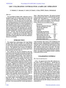
ARCHITECTURE OF THE LHC COLLIMATOR CONTROLS The proposed architecture of the LHC collimator control system [2] is shown in Fig.1. The system consists of three distinct levels [2, 3, 4]: 06 Instrumentation, Controls, Feedback & Operational Aspects
344
Figure 1: Architecture of the LHC collimator controls. 1. The lowest level [3] consists of Motor Driver Control, Position Readout and Survey and Environmental Surveillance units. The real-time control will be based on two distinct PXI platforms by National Instrument for the driver control and for the collimator surveillance. These units will be installed in underground low radiation areas at distances of up to 1.5 km from the collimators. Each unit will also be linked to the LHC beam interlock system to trigger beam dumps if measurements of jaw positions, collimator gaps or temperature will go beyond specified safe limit functions or in case of system faults. 2. A Collimator Supervisor System (CSS) is used at the middle level to control and supervise up to 40 collimators, grouped depending on their location in the ring (1 server will be installed per straight section). This middle tier will be implemented in terms of the FESA (Front-End Server Architecture) server, which is a standard software framework used in LHC, and will be used to orchestrate the synchronized movements of all motor controllers and to present the current position information in a standardized format. The CSS has also interfaces to the LHC beam loss monitoring for the implementation of automated algorithms for beam-based collimator optimization. 3. A central collimation application software is used to provide a coherent interface to all collimators of LHC ring and injection lines. This application will be used from the control room to generate the settings and interlock functions of each collimator and to control and optimize the overall system from the control room. T04 Accelerator/Storage Ring Control Systems
c 1-4244-0917-9/07/$25.00 2007 IEEE
Proceedings of PAC07, Albuquerque, New Mexico, USA
MOPAN081
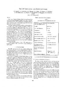
2.0 BLM 1 BLM 2 BLM 3 BLM 4
Beam loss signal [ a.u. ]
1.6
1.2
0.8
0.4
0.0 0
Figure 2: Architecture of the top-level collimator controls.
10
20
30
40 50 Time [ ms ]
60
70
80
Figure 3: Transient beam loss signals synchronized to a jaw movement. Buffers of 32 points at sampling times of 2.58 ms were saved for each movement request. 350
BEAM TEST SET-UP The proposed controls architecture has been partially assessed in real accelerator environments with beam tests performed in 2006 at the CERN Super Proton Synchrotron (SPS). The beam experiments included (1) tests with circulating proton beams at the SPS, performed with the full scale collimator prototype already used in 2004 [7], and (2) tests with extracted LHC-type beams in the TT40 line during a collimator material robustness experiment. The full three-tier controls architecture was deployed for the experiment (1) with circulating beam and allows to asses the validity of the control choices and the main functionalities provided by the control application. More details are discussed in a companion paper [8]. The position sensors of the SPS collimator could not be upgraded to the LHC-type LVDT’s. On the other hand, the final sensors and electronics could be tested in the TT40 robustness test (2) on a special collimator prototype (single jaw, special tank design, dedicated local control system). This allowed testing the final configuration in an accelerator environment. Four LHC-type ionization chambers and electronics were used for the SPS tests with circulating beams [8]. The on-line display of the 1.3 s integrated losses induced by collimator movements were used for the beam-based tuning of 06 Instrumentation, Controls, Feedback & Operational Aspects
c 1-4244-0917-9/07/$25.00 2007 IEEE
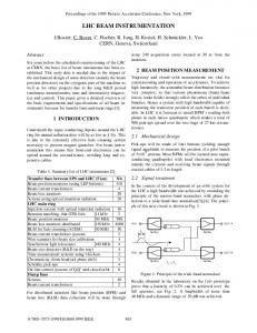
Avergage Minimum Maximum Ideal (2 mm/s) Difference to ideal
300 Execution time [ ms ]
More details of the top-level control application are shown in Fig. 2 [4]. The collimator application will rely on various packages developed within the LHC Software Application (LSA) [5] such as the LSA-TRIM, the setting generation and drive hardware functionality. Appropriate collimator tables will be defined in existing LSA databases. Critical collimator parameters will be handled in a secure way by the MCS (Management of Critical Settings) [6]. In order to ease the collimator operation, settings in unit of beam sigma will be possible from the top-level and appropriate function editors will be provided to generate and edit functions for the settings and for the interlock limits (which will be under the responsibility of authenticated expect collimator operators). The application will also provide the online display of the relevant collimator parameters from the surveillance units and of other required beam measurements (beam losses, orbit, experiment background, ...).
250 200 150 100 50 0
0
0.1 0.2 0.3 0.4 0.5 Requested displacement [ mm ]
0.6
Figure 4: Elapsed time between CSS motion requests and acknowledgment of motion execution from motor drive controller for different requested displacement sizes. the collimator position. In addition, the acquisition of integrated losses over 2.58 ms was also tested. These fast acquisitions were triggered by a synchronization signal sent from the CSS to the BLM post-mortem acquisition buffer (40 μs sampling rate). An example for to a jaw movement of 50 μm is shown in Fig.3. Further studies are needed to optimize the acquisition parameters in view of the implementation of automatic optimization procedures.
RESULTS FROM BEAM TEST The performance of the control system deployed for the beam tests was in general very satisfactory. The system was up and running during the whole beam time and provided the expected functionalities for single collimator controls [8]. Occasionally performance issues were experienced at the top-level, probably induced by a graphical package used for display purposes. These problems are under further investigation. The available controls advanced significantly the performance achieved during the 2004 tests. The proposed technical choices, in particular the PXI platforms for the low-level and the LVDT for the jaw position survey, were validated and will be adopted for the LHC. Figure 4 shows the response time of the overall lowlevel controls for movement requests of different amplitudes. This is calculated as the delay between the request sent by the CSS server and the “motion completed” acknowledgment from the motor controller (signal transmission through normal network, does not apply to data from T04 Accelerator/Storage Ring Control Systems
345
Proceedings of PAC07, Albuquerque, New Mexico, USA 4015
0.02 Jaw position [ μm ]
+10 μm 0.01 0 -10 μm
3995
Settings Measurements
55
5
Figure 5: Reproducibility of the jaw position as measured with the LVDT sensor during 36 calibration sets. post-mortem buffer). By correcting for the finite motor speed of 2 mm/s one can see that the total average delays are in average below 20 ms (red line). This is considered sufficient for the LHC requirements. Occasionally the response time was larger, up to 50 ms (green dashed line). The impact of these delays is under investigation. Figure 5 shows an example of LVDT calibration done remotely during the TT40 test with LHC-type sensors. The jaw is moved in steps of 1 mm from the outside of the jaw (-30 mm) to the full in position (+5 mm) across the nominal beam centre (0 mm). This procedure was repeated for 36 times from the low radiation underground area, with no human intervention on the collimator. The results are summarized in Fig. 5. It is shown that the absolute reproducibility of the jaw positioning is well within the ±10μm level, which is specified as LHC tolerance (20 μm correspond to about a tenth of a typical beam sigma at 7 TeV). The larger error at the out position (-30 mm) is determined by the mechanical plays, which will be measured for each jaw motor during hardware commissioning and thus it will be possible to compensate for them in operation. Figure 6 shows the jaw position and temperature during the TT40 robustness test. The jaw was kept into the beam path and hit by several beam shots (up to 3 × 10 12 p at 450 GeV). Each spike in the temperature signal corresponds to a direct beam impact on the Carbon jaw. Shifts of the jaw position were also induced. The noise level of the LVDT is of the order of 1-2 μm and is not significantly affected by the temperature variations. The good performance of the LVDT’s is also confirmed by the measurements carried out during several hours after the last impact, see Fig.7. While the jaw is cooled, the measured signal varies by at most 5 μm in more than 10 hours for temperature variations of about 20 degrees. This is a cumulative effect of real jaw deformations and sensor response to temperature variations. The sensor temperature will actually be monitored at the LHC and compensations of temperature effects on the sensor readout will be possible.
CONCLUSIONS We presented the architecture of the LHC collimator control system and the main results from controls prototyping in real accelerator environments (SPS ring and LHC transfer line). Several important components of the proposed design were assessed and approved. The implemen06 Instrumentation, Controls, Feedback & Operational Aspects
346
4000
50
45
40
2.2
2.4
2.6 Time [ s ]
2.8
3
3.2
Figure 6: Jaw position (top) and temperature (bottom) during consecutive beam impacts at the TT40 robustness test. 6
6 Upstream Downstream
Upstream Downstream
4
4 Jaw Position [ μm ]
-20 -10 0 Collomator jaw position [ mm ]
4005
3990
-0.02 -0.03 -30
4010
Jaw temperature [ deg ]
-0.01
Jaw Position [ μm ]
Error of set position [ mm ]
MOPAN081
2
0
-2
-4 0
2
0
-2
5
10
15
-4 25
Time [ h ]
30 35 40 Jaw temperature [ deg ]
45
Figure 7: Position of upstream and downstream jaw sides versus time (left) and temperature (right) at TT40. tation into the LHC has started. However, various other important milestones have to be achieved. In particular, next studies will be focused on the consolidation of the components tested so far, on the implementation of function driven collimator movements and threshold limit functions and on the extension of the system to achieve a synchronized control of the LHC multi collimator system. The authors would like to acknowledge many colleagues who contributed to the beam test, in particular C. Zamantzas and S. Jackson from the BLM team and the SPS operation crew, the LSA team, J. Wenninger, D. Jacquet, A. Brielmann, M. Donze e J. Lendaro. The LVDT’s were designed for our application by Schaevitz [10].
REFERENCES [1] R. Assmann et al., “Collimators and beam absorbers for cleaning and protection,” Chamonix workshop (2005). [2] M. Jonker et al., ”The control architecture for the LHC collimation system,” ICALEPCS2005 (2005). [3] A. Masi and R. Losito, “LHC Collimator Lower Level Control System,” 15th IEEE NPSS Real Time Conference 2007. [4] S. Redaelli et al. CERN EDMS doc. no. 826861 (2007). [5] http://ab-project-lsa.web.cern.ch/ab-project-lsa
[6] V. Kain et al. CERN EDMS LHC-CI-ES-0003 (2006). [7] R. Aßmann et al., “LHC collimation: design and results from prototyping and beam tests,” PAC05. [8] T. Weiler et al., these proceedings. [9] C. Zamantzas et al., CERN-AB-2007-010 BI (2007). [10] http://www.meas-spec.com/myMeas/MEAS download/ ApplicationNotes/Position/SchaevitzCernWP 0507.pdf
T04 Accelerator/Storage Ring Control Systems
c 1-4244-0917-9/07/$25.00 2007 IEEE