LASER INTERFEROMETER GRAVITATIONAL WAVE OBSERVATORY - LIGO – CALIFORNIA INSTITUTE OF TECHNOLOGY MASSACHUSETTS INSTITUTE OF TECHNOLOGY Document Type publication
DCC Number LIGO-P010035-00-D
Date 30th of October 2001
The Linear Variable Differential Transformer (LVDT) position sensor for Gravitational Wave Interferometer low-frequency controls. HareemTariq, Akiteru Takamori, Chenyang Wang, Riccardo DeSalvo, Alberto Gennai, Lee Holloway, Giovanni Losurdo, Szabolcs Márka, Federico Paoletti, Diego Passuello, Virginio Sannibale, Ruggero Stanga
Distribution of this draft: TBD Paper submitted to Nuclear Instruments and Methods California Institute of Technology Massachusetts Institute of Technology LIGO Laboratory - MS 18-34 LIGO Laboratory - MS 16NW-145 Pasadena CA 91125 Cambridge, MA 01239 Phone (626) 395-212 Phone (617) 253-4824 Fax (626) 304-9834 Fax (617) 253-7014 E-mail:
[email protected] E-mail:
[email protected] www: http://www.ligo.caltech.edu/
1
The Linear Variable Differential Transformer (LVDT) position sensor For Gravitational Wave Interferometer low-frequency controls.
HareemTariq(a,b), Akiteru Takamori(a,c), Flavio Vetrano(f,j), Chenyang Wang(a), Alessandro Bertolini(a,g), Giovanni Calamai(f,i), Riccardo DeSalvo(a), Alberto Gennai(d), Lee Holloway(e,d), Giovanni Losurdo(f), Szabolcs Márka(a), Massimo Mazzoni(f,h), Federico Paoletti(d), Diego Passuello(d), Virginio Sannibale(a), Ruggero Stanga(f,h).
a) b) c) d) e) f) g) h) i) j) (*)
LIGO project, California Institute of Technology, 1200 E. California Bl., Pasadena, CA, 91125, USA Florida Institute of Technology, 150 W. University Bl., Melbourne, FL, 32901, USA Department of Physics, University of Tokyo, 7-3-1 Hongo, Bunkyo-ku, Tokyo 113-0033, Japan INFN Sezione di Pisa, via Livornese 1291, S. Piero a Grado, 56100 Pisa, Italy Dept. Of Physics, University of Illinois at Urbana-Champaign, 901 West Illinois Street, Urbana, IL 61801 INFN Sezione di Firenze, via G. Sansone 1, 50019 Sesto Fiorentino, Firenze, Italy Dipartimento di Fisica, Universita’ di Pisa, via F. Buonarroti, 4, 56100 Pisa, Italy Dip. di Astronomia e Scienze dello Spazio, Universita' di Firenze, Largo E. Fermi 2, 51125 Firenze, Italy Osservatorio di Arcetri, Largo E. Fermi 4, 51125 Firenze, Italy Istituto di Fisica, Universita di Urbino, via S. Chiara 27, 61019 Urbino, Italy Corresponding authors,
[email protected] and
[email protected]
Abstract Low-power, Ultra-High-Vacuum compatible, non-contacting position sensors with nanometer resolution and centimeter dynamic range have been developed, built and tested. They have been designed at Virgo as sensor for low frequency modal damping of Seismic Attenuation System chains in Gravitational Wave interferometers and sub-micron absolute mirror positioning. One type of these LVDT’s has been designed to be also insensitive to transversal displacement thus allowing 3D movement of the sensor head while still precisely reading its position along the sensitivity axis. A second LVDT geometry has been designed to measure the displacement of the vertical seismic attenuation filters from their nominal position. Unlike the commercial LVDTs, mostly based on magnetic nuclei, the LVDTs described here exert no force on the measured structure.
Introduction One of the most simple and effective Seismic noise Attenuation Systems for Gravitational Wave Detection interferometers1,2,3 is a chain of pendula4,5,6,7,8 suspended from a very low frequency stage called Inverted Pendulum (IP). The IP 9,10 has the triple function of, • Pre-filtering low frequency seismic noise to diminish the excitation of the rigid body motion resonance of the attenuation chain; • Provide a suitable platform to damp the above mentioned resonance; • Provide the mechanical compliance to allow precision positioning of the mirror suspended from the chain using small forces. The attenuation chains provide seismic attenuation in the frequency region of interest for gravitational wave detection and are capable of delivering the required seismic attenuation factors (~10-10) above 5 to 10 Hz, depending on the pendula lengths. The IP is composed of three flex joints, each supporting a leg. At the top, the three legs are connected to a rigid table by means of small flexures.
The IP has two
translational modes and one torsional mode. A triplet of accelerometers11,12 is mounted at 120o, in pinwheel geometry, at the periphery of the IP top table. It is designed to detect the acceleration in the IP’s three degrees of freedom. Their signal is fed to actuators13 to damp the rigid body resonant modes of the chain14,15,16, and hence reduce the mirror r.m.s. residual motion of the suspended mirror to a few tens of nanometers in the frequency band between 10 mHz and 5 Hz.
The accelerometers are inertial sensors, totally insensitive to velocity, and cannot provide positioning of the IP table (and of the mirror suspended from it) with respect to a local frame. Additionally, at low frequency (typically below 100 Hz, depending on the mechanics precision and ground stability) inertial sensors can be more sensitive to tilts than to real accelerations.
In order to take full advantage of the accelerometer
performance it is necessary to complement them with a set of high precision position sensors. The specifications of these position sensors are as follows: • Linearity within 1% over +/-10 mm, to match the typical IPs dynamic range • Position resolution ~ 10 nm r.m.s. to allow the reduction of mirror residual motion • Insensitivity to movements in the directions orthogonal to the sensing axis, to allow for free movements of the IP on the horizontal plane and not to re-inject seismic signals from the orthogonal directions in the feed back loop • Force-free and contact-free, to avoid short circuiting of the seismic excitation to the IP table • Only passive components inside the vacuum system, for reliability reasons • Fully UHV compatible, to prevent contamination of the vacuum conditions.
Special LVDT position transducers have been designed for the GW interferometer VIRGO, to satisfy all the above requirements. Note, also, that all the electronic circuitry is placed outside the vacuum enclosure to satisfy the passive instrument requirement. The LVDT are driven and read-out at the end of 20 or more meters of twisted shielded cable without loss of resolution. They turned out to be so versatile that a modified, smaller version (that has been defined as a “second type”) has been designed, which is
being used in several other locations of the GW interferometer seismic attenuation systems, as a sensor for all the Virgo superattanuator filter vertical working point, in the TAMA MGASF top filter, and as generic precision position sensor in mechanics R&D17.
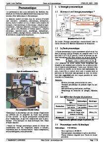
The LVDT working principle The LVDT is composed of three coils whose cross section is shown in Figure 118. The central emitter coil, driven with a sinusoidal signal at a frequency between 10 and 20 kHz, mounted between two larger receiver coils; the two receiver coils are identical, counter-wound and connected either in series or in parallel. The emitter is mounted on the IP table while the two receivers are attached on a reference structure; when the emitter is exactly in the mid point between the twin receiver coils, no net signal is induced. When the table movements move the emitter coil in a direction, a sinusoidal signal appears on the receiver coils. This signal has amplitude roughly proportional to the displacement from the center position. If the coil is moved in the opposite direction the sign of the induced sinusoid is changed. By a careful choice of the coil geometry it was possible to get better than one percent linearity over 25 mm of movement range with less than a percent sensitivity to transversal movements. Also the sophisticated design of the lock in amplifier circuit allowed for better than 10 nm r.m.s. position resolution over the afore mentioned range. The coils are made of Kapton-coated copper wire, wound around glass or Peek supports, and are therefore completely UHV compatible.
Although the coils were
accurately spooled, the lumped coil of this design makes it quite insensitive to the spooling precision.
Unlike conventional magnetic core LVDTs19, this arrangement has no ferromagnetic components and does not generate to unwanted forces when exposed to external magnetic fields
Figure 1: Schematic view, sectioned along the symmetry axis, of a LVDT position transducer. The three coils appear as the six darkly shaded rectangles. The coil spools are made of either glass or Peek, the coil supports are made of slotted and mutually isolated aluminum parts to avoid eddy current loops.
No effort is made to make thermally
compensated supports because they are intended for use in a thermally stabilized vacuum envelope.
The one percent linearity and transversal motion insensitivity are obtained by using two simple circular coils wired in series and placed in a Maxwell Pair (MP) configuration. The MP configuration is related to the better-known Helmoltz Coils (HC) configuration. The HC coil is optimized to deliver a magnetic field intensity as uniform as possible over a volume as large as possible at the center of the pair. The MP is designed to deliver a maximally uniform field gradient over the same volume. The MP configuration is slightly less compact than the HC one; in the MP the coil separation s is s=r 3
where r is the coil radius
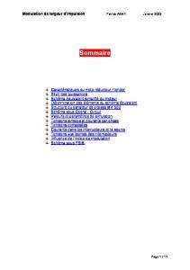
The MP pairs also differ from the HC because the current flows in opposite directions in the two receiver coils to generate the linear position signal of the LVDT. If the two MP coils had parallel and same direction field, the emitter coil would induce a signal insensitive to position. Opposite current flow in the windings induces null signal at the central position while a remarkably linear signal is obtained along the displacement when the emitter coil moves along the MP symmetry axis. The instrument remains insensitive to movements along other two axis. The MP has a reasonably large sweet spot (~20% of the volume). As long as the emitter coil remains in the sweet spot, good linearity and insensitivity to transversal motion is achieved. An example of the calculated linearity is shown in Figure 2.
percentage deviation from constant gradient
0.2
0
-0.2
-0.4
-0.6
-0.8
-1 -15
-10
-5
0
5
10
15
displacement (mm)
Figure 2: Percentage deviation of the magnetic field gradient along the sensitive axis of the LVDT.
LVDT measured performances The LVDT is expected to be linear well below a percent over a range of 30 mm and it is quite insensitive to movements in the other two orthogonal directions. The expected linearity is confirmed by the calibration of the actual instruments. The emitter coil is moved along the LVDT axis with the help of a micrometric positioning stage.
A
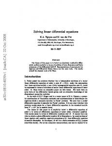
calibration constant of about 500 mV/mm was obtained as shown in Figure 3 (top), with less than +/-1% deviation from the linearity; Figure 3 (bottom). The very symmetric and
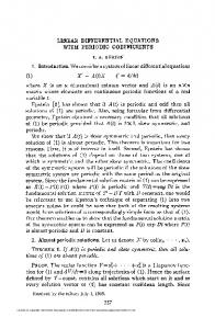
almost sinusoidal residuals seem to point to geometrical effects due to the non-negligible thickness of the three coils or to the imperfect spacing of the two receiver coils. Alignment errors of the emitting coil with the receiving coils’ symmetry axis affect the LVDT sensitivity only to the second order and may introduce some unwanted sensitivity to transversal motions. The insensitivity of the LVDT to transversal motion is shown in Figure 4. Only the trend of the measured distribution is important. The dispersion of the measurement points is due to a small wobble of the micrometric sled in the magnetic field gradient direction, because the equations of magnetic field in vacuum require smoothness of the LVDT response. The flat trend of the measurement proves that the actual sensitivity of the LVDT to transversal movements is very small up to a radial distance of 12 mm.
readout (mm)
15
10
5
0
-5
-10
-15
residuals (mm)
-15
-10
-5
0
5
10
15
5
10
15
0.3 0.2 0.1 0 -0.1 -0.2 -15
-10
-5
0
displacement (mm)
Figure 3: Calibration measurement of an IP LVDT (top) and its residuals from a linear fit (bottom).
readout variation (mm)
0.015
0.01
0.005
0
-0.005
-0.01
-0.015 0
2
4
6
8
10
12
14
transversal displacement (mm)
Figure 4: Sensitivity of a LVTD to transversal motion.
In principle the LVDT position resolution is only limited by the electronics noise. The electronics noise is kept low by using a simple phase locked signal detection technique. The signal sent to the emitter coil is also used to synchronize a low noise, double input linear gate. The amplified signal of the receiver coils and its opposite are sent to the two alternate gate inputs. For a more detailed discussion of the electronics see ref.20. The actual circuit can be found in ref.21.
In the IP configuration of the LVDTs, described above, a resolution of 20 nm was achieved, as shown in Figure 5. Further electronics noise improvements have led to LVDT resolution twice as good as what is shown in Figure 5; it is less than 10 nm r.m.s..
Other applications of LVDTs Smaller versions of the LVDTs, with a different geometry, shown in Figure 6,
22
have been used to generate diagnostics of passive filters of the attenuation chains in the Virgo superattenuators4 and position feedback signals in the top filter both in the superattenuators and in the TAMA-SAS23. They have been used also as position sensor in R&D creep measurements17.
displacement noise [nm/Hz-1/2]
100
10
1
0.1 0.1
1
10
100
1000
Frequency [Hz] Figure 5: Spectral r.m.s. position resolution of the LVDT. The apparent drop off of the residual noise above 50 Hz is generated by the low pass filters after the demodulation and it is not an indicator of improved sensitivity.
These smaller LVDTs have a simpler, monolithic geometry and rely on a different geometry to achieve good linearity. They are made with long, thin, uniformly wound cylindrical coils rather than with short, lumped, loop-like coils. Similarly good linearity is achieved by choosing the right coil aspect ratios (Fig. 6). While mechanically much simpler and self-supporting, a feature quite useful for small geometries, these coils are more sensitive to the smoothness of the coiling of the wire around the spool. Even small imperfections of coiling are easily detectable as local perturbations on the linearity of the response. The LVDTs are obviously very sensitive to the coil spool stability. In a creep measurement where nylon spools were used, the creep signal was actually dominated by the spool shrinking while it itself progressively dried up in the dry thermally stabilized measured chamber24. Ceramics or Peek coil spools have been successfully used as a replacement to avoid this problem and to achieve the desired signal stability17. While the linear dynamic range of these smaller LVDTs is similar to that of the bigger LVDT versions (Figure 7), they do not allow much of a lateral movement and are used only where the mechanics demands a purely linear response. These small LVDTs are routinely used with higher gain (in part obtained with more coil layers in the emitter and in part electronically) to drive their position resolution below nm level. This is obtained at the price of a dynamic range reduced to a few mm only.
Figure 6: Geometry of a small LVDT. The emitter coil is 9 mm in diameter and 18 mm long. The receiver coils are continuously wound on a spool 24 mm in diameter, 28 mm long; the first 14 mm are wound in one direction and the remaining 14 mm are counterwound; in the drawing a gap is shown in the center to show where the winding direction changes. The receiver coils are wound in a single layer without any space between each wire turn. In the emitter more than one layer is often wound to improve the sensitivity.
readout (mm)
20
15
10
5
0 0
5
10
15
20
Displacement (mm)
residuals (mm)
0.06 0.04 0.02 0 -0.02 -0.04 -0.06 0
5
10
15
20
Displacement (mm)
Figure 7: Linearity performance of the small LVDT of Figure 6.
Problems due to electronics The LVDT drivers are sensitive to variation of amplitude of the excitation signal. Special care was in designing the LVDT driver card in order to generate a suitably stable excitation signal. These internal frequency generators of the LVDT drivers are perfectly adequate when absolute positioning resolution is not an issue, like for example in mode damping feedback circuits, where drifts