International Archives of the Photogrammetry, Remote Sensing and Spatial Information Sciences, Volume XXXVIII-1/C22, 2011 ISPRS Zurich 2011 Workshop, 14-16 September 2011, Zurich, Switzerland
THE PIXHAWK OPEN-SOURCE COMPUTER VISION FRAMEWORK FOR MAVS Lorenz Meier and Petri Tanskanen and Friedrich Fraundorfer and Marc Pollefeys Institute for Visual Computing, Computer Vision and Geometry Lab Swiss Federal Institute of Technology / ETH Zurich CAB G 86.3, Universitaetstrasse 6, 8092 Zurich
[email protected],
[email protected],
[email protected],
[email protected] http://www.cvg.ethz.ch
KEY WORDS: UAVs, MAVs, computer vision, open source, middleware, hardware
ABSTRACT: Unmanned aerial vehicles (UAV) and micro air vehicles (MAV) are already intensively used in geodetic applications. State of the art autonomous systems are however geared towards the application area in safe and obstacle-free altitudes greater than 30 meters. Applications at lower altitudes still require a human pilot. A new application field will be the reconstruction of structures and buildings, including the facades and roofs, with semi-autonomous MAVs. Ongoing research in the MAV robotics field is focusing on enabling this system class to operate at lower altitudes in proximity to nearby obstacles and humans. PIXHAWK is an open source and open hardware toolkit for this purpose. The quadrotor design is optimized for onboard computer vision and can connect up to four cameras to its onboard computer. The validity of the system design is shown with a fully autonomous capture flight along a building. 1
INTRODUCTION
problems of autonomous flight, however small scale MAVs also allow indoor operation (e.g. for as built documentations of facilities) and for such applications different methodologies than GPS need to be developed. This applies also to outdoor applications where fully autonomous or semi-autonomous data capturing is necessary, but GPS reception is weak (Irschara et al., 2010).
Already today UAVs and MAVs play a big role in photogrammetric and geodetic applications (Eisenbeiss, 2009, Eisenbeiss et al., 2005). While the larger Unmanned Air Vehicles are typically used in environments in the square kilometer range, Micro Air Vehicles are more suitable for smaller areas or urban environments. One of the main applications is the generation of aerial imagery for digital elevation model (DEM) generation, orthophoto generation and 3D reconstruction and modeling. Compared to standard aerial imaging these small-scale flying vehicles offer new and unconventional camera viewpoints and more closeup views. This makes it easier to fuse street-level imagery and aerial-imagery to use both sources to create complete 3D models of buildings. In addition to these well known photogrammetric application new industrial applications start to emerge as well. MAVs can provide easy access for visual inspections of high rising industrial structures and plants. Road inspection and traffic analysis are other application fields that are also well suited for UAVs or MAVs (Zhang, 2008, Mori et al., 1996). Environmental monitoring in general holds big application areas for UAVs and MAVs. In particular if the UAVs fly autonomously and are able to perform the monitoring fully automatic. One big application area to come is the use of UAVs and MAVs to aid in emergency response (Choi et al., 2009, Haarbrink and Koers, 2006). They could provide aerial views of the catastrophe scene which allows the first responders to efficiently manage their efforts. This however would require fully autonomous MAVs that are easy to handle and do not require trained operators. Autonomous flight would be most beneficial for all the other application areas as well. The need for trained operators limits the application areas severely and thus this should be one of the top priorities of MAV research. Many application areas would already heavily benefit from semi-automatic flight, such that not trained personnel can fly the MAVs. Such semi-automatic MAVs would at least be able to hover on spot without input, perform a safe landing autonomously and are able to detect obstacles to prevent the operator from crashing the MAV. One such example are archeological applications where the system would be operated by non-trained personnel (Oczipka et al., 2009, Sauerbier and Eisenbeiss, 2010). For applications in open areas GPS can be used to solve many
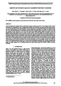
Optimal MAV Altitude
Airspace
Rooflevel
Streetlevel
Figure 1: Optimal MAV operational altitude between street level and roof level. This range is not accesible for UAVs or hand-held cameras. 1.1
MAV specific capabilities
In contrast to larger UAVs, MAVs can operate in a lower altitude range and closer to buildings and installations. On the operational level, their substantially reduced weight and kinetic energy in case of system or operator failures is a very important property for the use of this system class in urban environments. This allows these systems to relatively easily cover the street-to-roof altitude range, as shown in Fig. 1. Current systems however require a very skilled pilot to be able to operate safely in urban environments. Adding onboard processing capabilities and stereo vision to the system allows it to not only fly a predefined course, but to also autonomously detect and avoid obstacles. This will be a critical step to enable full autonomous data capture by untrained operators. Autonomous MAVs will allow the efficient, low-cost and high-
13
International Archives of the Photogrammetry, Remote Sensing and Spatial Information Sciences, Volume XXXVIII-1/C22, 2011 ISPRS Zurich 2011 Workshop, 14-16 September 2011, Zurich, Switzerland
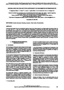
resolution 3D reconstruction of individual buildings and eventually of whole cities. Any ground-based capturing device would not be fast and flexible enough for this task and UAVs cannot reach the required view points. Fig. 2 shows the output of a MAV flight in the street-to-roof altitude range. The reconstruction includes the facade and roof at high resolution.
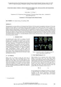
Captured Object
Evaded Obstacle
Landing Pad with Markers
Figure 3: Concept showing MAV performing a semi-autonomous capture flight with user-defined trajectory, starting / landing aids and autonomous obstacle avoidance during flight. (Jensen et al., 2008). Although the software can be run also on Linux, the toolkit is however geared towards the flight control of the UAV and does not provide any image processing or mapping infrastructure. The OpenPilot project 1 is a relatively new open source toolkit for micro air vehicles, currently solely used on microcontrollers without any computer-connection option. Ground robotics toolkits offer a very wide range of sensor drivers and computer vision and simultaneous localization and mapping (SLAM) packages. Their communication infrastructure does however require all components to support either TCP/IP or UDP connections. CLARAty (Volpe et al., 2001) and shortly after CARMEN (Montemerlo et al., 2003) were very early toolkits paving the way for standardization in robotics. Since ROS (Quigley et al., 2009) was released more recently, their use has declined. ROS has been adopted on micro air vehicles. It requires however bridge processes for the communication to the onboard autopilot and external radio modems.
Figure 2: Sparse 3D reconstruction from flight images. Note that for the reconstruction of the facade and roof a MAV is necessary, as UAVs or ground-based cameras cannot reach these viewpoints. 1.2
3
OPEN SOURCE SYSTEM DESIGN
Towards semi-autonomous data capture The PIXHAWK MAV toolkit is geared towards computer-vision enabled MAVs. It facilitates the interfacing of cameras and autopilots and provides a graphical user interface for the ground control station. This setup allows to quickly develop computervision enabled systems handling up to four cameras in parallel. By synchronizing the cameras with a hardware-shutter to the inertial measurement unit, all camera images are available synchronized and annotated with inertial and GPS information. This allows to employ new localization algorithms which exploit the additional information in the image. As computer-vision-based localization techniques typically have a relatively long and varying processing time depending on the current image content, the position estimator has to account for this variable delay. The attitude sensors on the inertial measurement unit have however virtually zero delay and a constant processing time. All estimation and control software components are implemented on the lowlevel ARM7 autopilot and all computer vision algorithms on the high-level image processing computer. This design allows to use a standard GNU/Linux (Ubuntu) operating system on the highlevel computer, while the system does not lose any of its realtime properties. Our natural feature based monocular localization technique is able to determine the system position at about 10-15 Hz using only one of the two cores of the onboard computer.
The fully autonomous vision-based operation of a MAV is still ongoing research. With the availability of strong and lightweight onboard computers it became however feasible to add a certain level of autonomy to a MAV. Computer-vision based localization techniques outperform GPS at low altitudes and perform well in urban-canyon like scenarios where reflections lead to a reduced GPS accuracy. Even in the absence of sufficient visual cues and texture vision-based techniques can perform well, by placing a low quantity of artificial markers on the ground. Onboard stereo cameras help to evade nearby obstacles and can enable the MAV to autonomously adjust its surface distance to reach the desired image ground resolution. All these steps will allow MAVs to be used by untrained operators soon. Fig. 3 shows the concept of a semi-autonomous capture flight with an operator- defined trajectory. The MAV performs autonomous obstacle avoidance to recover from suboptimal user input. Additional aids in form of artificial visual markers can be provided in challenging environments and critical flight phases, such as during takeoff and landing. 2
RELATED WORK
Several open source frameworks exist for micro air vehicles and ground robots. While the MAV frameworks are focused mostly on flight control and do not provide any significant robotics infrastructure, the ground robot toolkits assume an Ethernet-based connection to all onboard components. The Paparazzi project was already used in photogrammetry to capture data sets on MAVs
3.1
Data synchronization and time stamping
If vision data is used the position estimation and control steps cannot rely on a fixed time interval between the position updates. 1 http://www.openpilot.org
14
International Archives of the Photogrammetry, Remote Sensing and Spatial Information Sciences, Volume XXXVIII-1/C22, 2011 ISPRS Zurich 2011 Workshop, 14-16 September 2011, Zurich, Switzerland
BlueFOX-MLC cameras. The core module is a custom baseboard in the COMExpress form factor for the Core2Duo / i7 module with interfaces needed on a MAV. As the baseboard has an industry standard etxExpress interface the onboard computer can be upgraded to newer hardware as soon as a new computer modules are released. All the IMU sensors and the flight controller are on an additional custom designed unit board, the IMU. Figures 5 and 6 show an overview of all the components. Due to the small size and weight of all components the hardware modules can be easily lifted with other kinds of UAVs as well.
Instead the system has to be able to cope with substantially differing intervals and should be able to measure the delay between image capture to localization output. Therefore the system timestamps all measurements and synchronizes them with microseconds resolution. This includes images from multiple cameras, data from the inertial measurement unit (system attitude, acceleration, barometric pressure) and GPS position. As a result of the precise time-stamping and the following synchronization of the different data sources every image taken by the system is extended with the full state at the very moment of image capture as meta data. This allows for new computer vision algorithms exploiting this information, i.e. making use of the known direction of the gravity vector. This allows to speed up some calculation steps for localization and triangulation and to make them more robust. 3.2
Harddisk S-ATA II solid-state
S-ATA
Image Processing Unit Intel Core 2 / i7 1.86- 2.00 GHz, 2-8 GB RAM pxCOMex Module Ubuntu Linux
USB
USB Wifi 802.11n Stick
USB 1x-4x Point Grey FireFly MV
Mechanical Structure and Flight Time
UART
Trigger
The custom mechanical design (Fig. 4) effectively protects the onboard processing module in case of a system crash and the fixed mounting of the four cameras allows inter-camera and cameraIMU calibration. As the focus of the frame design is on a large payload, the overall system structure has been optimized for low weight. It consists of lightweight sandwich material with composite plates and an inner layer made of Kevlar. Since all CAD files of the mechanical elements are available as open hardware designs, custom changes like wider stereo baselines or different camera mounts are easily possible. In the current design, the four motors with 10” propellers contribute a maximum of 600g thrust each, enabling the system to lift 1kg payload at a total system weight of 1.6 kg, including battery. The flight time in this configuration is typically 12 minutes. The propulsion consumes 280W for hovering, while the onboard computer consumes only 27 W peak. Therefore flight time is governed by the weight of the system.
XBee Radio Modem
UART + USB
Autopilot and IMU Module ARM7 60 MHz pxIMU Module
I2C
4x Brushless Motor Controller
Figure 6: Onboard sensors and avionics with electronic buses. 4
MAVLINK
The MAVLink open source communication protocol is designed to scale to different wireless and wired links from serial (UART) to UDP. It it used throughout the system, not only for wireless communication with the operator control unit but also serves as communication protocol between the flight computer (IMU) and the onboard main computer. It is able to use several links in parallel, allowing to use several redundant links, in this case longrange XBee radio modems and 802.11n WiFi (UDP); for even longer ranges it is possible to use GSM modems. The protocol uses only 8 bytes overhead per packet and has in-built packetdrop detection. Due to the low overhead and efficient encoding it allows to execute the protocol on low performance microcontrollers. As Fig. 7 and Fig. 8 show, MAVLink has been widely adopted in the open-source domain, with more than six different external autopilots and four different ground control stations supporting the protocol.
Figure 4: Overview of all hardware components. 3.3
Flight and Processing Electronics
Figure 7: Autopilots using MAVLink as protocol: ArduPilot Mega, UAV Dev Board, FlexiPilot, AutoQuad, PX2FMU, IMU, SLUGS autopilot (not shown). Figure 5: From left to right: Autopilot, image processing module, microETXExpress Core 2 DUO 1.86 GHz module.
The systems implementing MAVLink range from research platforms to commercial systems. IMU and QGroundControl represent the original pair of autopilot and ground control station used together, but now an arbitrary combination of autopilot and ground control station can be used with the protocol.
The electronics hardware consists partly of commercial off-theshelf products like the Core2Duo / i7 COMex processing module and four PointGrey Firefly MV USB 2.0 or MatrixVision
15
International Archives of the Photogrammetry, Remote Sensing and Spatial Information Sciences, Volume XXXVIII-1/C22, 2011 ISPRS Zurich 2011 Workshop, 14-16 September 2011, Zurich, Switzerland
used to send system states and control commands that are rather small, MAVCONN implements a convenient high-level programming interface (API) to a shared memory based image hub on the onboard computer. It allows to share the images of all cameras with an arbitrary number of Linux processes with the least overhead possible. Although LCM is used as base middleware it is possible to include ROS nodes into the system through the MAVCONN ROS-MAVLink bridge process that routes messages between both middlewares.
All MAVLink messages are generated from a XML protocol specification file. Currently code generators for C89-compatible C, Python and Java are available. The generated code contains all messages defined in the XML specification as well as functions for message packing and unpacking. This makes it very convenient to implement the protocol on different systems. Another important property of the protocol is its extensibility: Users can extend the default XML files and introduce their own custom messages. The code gets automatically generated and no manual coding is necessary.
5.1
QGroundControl
APM Planner
HK GCS
CopterControl
As a quadrotor is aerodynamically unstable, it will not stay at a given position without active attitude and position control. The current position is estimated using 2D-3D correspondences in the current camera frame combined with inertial measurements and a global map of previously mapped 3D points (Kukelova et al., 2011). The autopilot calculates the desired attitude and controls the attitude using its onboard inertial sensor suite. The system can additionally use its stereo cameras to recognize obstacles in the proximity of the helicopter. The obstacles are stored in a local map that holds all detected obstacles near the helicopters position. If the operator commanded the helicopter to take a path that crosses an obstacle the helicopter will recognize it and depending on the settings stop and hover or actively re-plan the flight path by taking the shortest path around the obstacle.
Figure 8: Ground control stations using MAVLink: QGroundControl (Win/Lin/Mac), APM Planner (Win), HK GCS (Win), CopterControl (Android phones). 5
Visual Position Control
6
OPERATOR CONTROL UNIT
AERIAL MIDDLEWARE
MAVCONN is a robotics toolkit tailored towards computer vision controlled autonomous lightweight MAVs. Most components are connected via serial links and USB. The main problem with the existing middleware toolkits is that they do not scale down to this kind of links since every packet has to be transcoded by bridge processes, increasing the transmission delay. This new architecture design can be transparently used on different hardware links and minimizes the system complexity. As shown in Figure 9, the PIXHAWK Linux middleware consists of several layered software components. This architecture allows to use the different base communication layers. The main communication layer uses LCM that outperforms ROS in terms of latency (Huang et al., 2010). An additional advantage is that LCM does not use any central server process for communication, directly increasing the robustness by eliminating the single point of failure when the central process crashes. Linux Vision Process
Memory
USB 2.0 Camera
USB
Linux Control Process
LCM/ROS
Image Bus (shared mem.)
LCM/ROS
Figure 10: Operator perspective using the 3D moving map with elevation data and city 3D models. The groundstation developed for the PIXHAWK platform is an open-source operator control unit and supports multiple autopilot types and can handle several airborne MAVs in parallel. QGroundControl has been implemented in C++ using the Nokia Qt toolkit. It is cross-platform and is available for Microsoft Windows, Mac OS X (10.5+) and GNU/Linux. The application supports the complete MAV lifecycle, starting from the development of onboard software and controllers over the actual mission control to post-mission data analysis and plotting. The application has three major user customizable perspectives: The operator, engineer and pilot views. Each of them consists of a number of user-interface elements (widgets), which can be freely positioned and resized by the user.
XBee Radio (Air)
UART
MAVLink broadcast (topic-filtered)
MAVLink
XBee Radio (Ground)
MAVCONN MIDDLEWARE UART
pxIMU Autopilot
WIFI/UDP
UART
QGroundControl GCS
Figure 9: MAVCONN Network showing different physical links using the MAVLink protocol.
Fig. 10 shows the 3D Google-Earth based mission view. This moving map allows to track a UAV flight path, to set and drag waypoints and to freely navigate the view around the globe. The data is provided by Google and, since it is cached on disk, the application can also be used without internet connection. The list
The MAVCONN middleware provides access to the different communication links to send MAVLink messages through out the system and to off-board nodes. While MAVLink messages are
16
International Archives of the Photogrammetry, Remote Sensing and Spatial Information Sciences, Volume XXXVIII-1/C22, 2011 ISPRS Zurich 2011 Workshop, 14-16 September 2011, Zurich, Switzerland
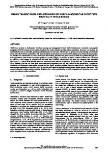
cores. The update rate is in the 10-15 Hz range. The experiment has been performed in a Vicon capture space to be able to compare the camera-based localization with ground-truth measurements. The Vicon motion capturing provides a localization accuracy with a position error < 1mm. Fig. 12 shows that the visual localization provides accurate results with a position error in most cases below 1 cm. The system can also employ optical flow for computer vision based localization and flight control.
below the 3D view shows the current mission, consisting of different waypoint elements. The same waypoints are shown in the 3D view. The status of the MAV is shown in the top right corner, which summarizes the battery level, position and internal state. The horizontal situation indicator (HSI) instrument below shows nearby obstacles, in this case the space is free. The crossed-out element indicates that no information is available for the infrared distance sensor. The head up display (HUD) with the artificial horizon indicated the current flight attitude of the system.
Fig. 13 shows a 3D map based on an autonomous wall-following flight without GPS support. This approach is already suited for autonomous capture flight along building structures. The system stabilizes its flight using optical flow and an ultrasonic altitude sensor while calculating the desired flight direction based on the stereo depth map. All image processing and flight control is onboard, allowing the quadrotor to operate autonomously.
Figure 11: Operator perspective using the 2D moving map for mission planning and control. Although the 3D interface allows to intuitively track the vehicle position and gives a good idea about the terrain elevation, the mission planning during flight operations is more convenient in the 2D map shown in Fig. 11. The map displays the current mission and shows also the type of waypoint (simple pass-through waypoints, circle loiter waypoints, liftoff and land). These waypoints represent the waypoint types in the MAVLink mission language. 7
Figure 13: Real-time and online 3D reconstruction from a fully autonomous flight where the quadrotor followed the wall to capture the building. The yellow ball is calculated based on the current depthmap and indicates the next position the system should fly to.
RESULTS AND DISCUSSION
Fig. 14 shows the flight trajectory as estimated by the system. Since it is an odometry implementation, it involves a bearing error at the 90 degree angle turn. As the flight direction is however depending only on the structure the system is capturing, this does not result in a position error with respect to the capture object. The quadrotor always keeps the same distance to the object and follows it contour. The obtained odometry from the flight control pipeline can later be used as initialization to a global optimization scheme, such as bundle adjustment.
The results presented here show two different localization techniques. Fig. 12 shows a global localization technique using natural features and IMU information to localize from two correspondences. Vicon ground truth 2pt visual localization
Z position (meter)
Odometry Flight Trajectory
1.5 1
10
0.5 0 8
Y Position (m)
−1 −0.8 −0.4 −0.6 −0.8
−0.6 −0.4 −0.2 0 X position (meter)
0.2
−1 −1.2 −1.4 −1.6 Y position (meter)
6
4
2
Figure 12: Trajectory of an autonomous flight using natural feature based localization. It is accurately following the Vicon ground truth.
-10
-5
0
X Position (m)
5
10
Figure 14: Flight trajectory from the wall following experiment computed by the online onboard odometry. The trajectory is not globally correct but it can be used as an initialization for global optimization.
The quadrotor is hovering above an aerial texture using a natural feature based localization. The position is computed completely onboard and consumes only one of the two available CPU
17
International Archives of the Photogrammetry, Remote Sensing and Spatial Information Sciences, Volume XXXVIII-1/C22, 2011 ISPRS Zurich 2011 Workshop, 14-16 September 2011, Zurich, Switzerland
8
CONCLUSIONS AND FUTURE WORK
Kukelova, Z., Bujnak, M. and Pajdla, T., 2011. Closed-form solutions to minimal absolute pose problems with known vertical direction. Computer Vision–ACCV 2010.
This work presented an open source platform for computer vision based MAVs for geodetic applications. The overall design of the system is geared towards the needs of vision based flight, such as precise time-stamping of IMU and visual measurements. The modular architecture of the middleware allows to easily implement additional software components or include new hardware sensors. The results include autonomous computer vision based indoor and outdoor flight, including an autonomous approach to follow building structures and create datasets for 3D reconstruction. Although the onboard-navigation does not globally optimize the map, it is suitable for large-scale autonomous data collection as only the local distance and bearing to the capture object is relevant. Global consistency can be obtained in an off-board mapping step.
Montemerlo, M., Roy, N. and Thrun, S., 2003. Perspectives on standardization in mobile robot programming: the carnegie mellon navigation (carmen) toolkit. In: Intelligent Robots and Systems, 2003. (IROS 2003). Proceedings. 2003 IEEE/RSJ International Conference on, Vol. 3, pp. 2436 – 2441 vol.3. Mori, M., Masahiro, S., Akamatsu, Y., Yamana, R. and Yahara, T., 1996. Discussion on the automatic measurement of traffic flow by video camera mounted on balloon. In: International Archives of Photogrammetry, Remote Sensing and Spatial Information Sciences. Oczipka, M., Bemman, J., Piezonka, H., Munkabayar, J., Ahrens, B., Achtelik, M. and Lehmann, F., 2009. Small drones for geoarcheology in the steppes: locating and documenting the archeological heritage of the orkhon valley in mongolia. In: Remote Sensing f. Environmtl. Monitoring, GIS Applications, and Geololgy IX, Vol. 7874, SPIE, pp. 787406–1.
Future work will include the refinement of the autonomous capture such that the camera viewpoints are well suited for 3D reconstruction while flying a minimal time or distance to obtain the dataset.
Quigley, M., Gerkey, B., Conley, K., Faust, J., Foote, T., Leibs, J., Berger, E., Wheeler, R. and Ng, A., 2009. Ros: An open-source robot operating system.
ACKNOWLEDGEMENTS
Sauerbier, M. and Eisenbeiss, H., 2010. Uavs for the documentation of archaeological excavations. In: International Archives of Photogrammetry, Remote Sensing and Spatial Information Sciences.
We would like to thank our students Laurens Mackay and Tobias N¨ageli for their contributions on optical flow based flight control and the students of the previous semesters for the foundations they provided. This work was supported in part by the European Communitys Seventh Framework Programme (FP7/2007-2013) under grant #231855 (sFly) and by the Swiss National Science Foundation (SNF) under grant #200021-125017.
Volpe, R., Nesnas, I., Estlin, T., Mutz, D., Petras, R. and Das, H., 2001. The claraty architecture for robotic autonomy. In: Aerospace Conference, 2001, IEEE Proceedings., Vol. 1, pp. 1/121 –1/132 vol.1. Zhang, C., 2008. An uav-based photogrammetric mapping system for road condition assessment. In: International Archives of Photogrammetry, Remote Sensing and Spatial Information Sciences.
REFERENCES Choi, K., Lee, I., Hong, J., Oh, T. and Shin, S. W., 2009. Developing a uav-based rapid mapping system for emergency response. Vol. 7332, SPIE, p. 733209. Eisenbeiss, H., 2009. UAV Photogrammetry. PhD thesis, ETH Zurich. Eisenbeiss, H., Lambers, K., Sauerbier, M. and Li, Z., 2005. Photogrammetric documentation of an archaeological site (palpa, peru) using an autonomous model helicopter. In: Proc. CIPA XX International Symposium, pp. 238–243. Haarbrink, R. B. and Koers, E., 2006. Helicopter uav for photogrammetry and rapid response. In: International Archives of Photogrammetry, Remote Sensing and Spatial Information Sciences. Huang, A., Olson, E. and Moore, D., 2010. LCM: Lightweight Communications and Marshalling. In: Intelligent Robots and Systems (IROS), 2010 IEEE/RSJ International Conference on, pp. 4057–4062. Irschara, A., Kaufmann, V., Klopschitz, M., Bischof, H. and Leberl, F., 2010. Towards fully automatic photogrammetric reconstruction using digital images taken from uavs. In: Proceedings International Society for Photogrammetry and Remote Sensing Symposium, 100 Years ISPRS - Advancing Remote Sensing Science. Jensen, A., Baumann, M. and Chen, Y., 2008. Low-cost multispectral aerial imaging using autonomous runway-free small flying wing vehicles. In: Geoscience and Remote Sensing Symposium, 2008. IGARSS 2008. IEEE International, Vol. 5, pp. V –506 –V –509.
18