all the different elements and protocols that were implemented .... 1 Samsung Transparent LCD. Each vehicle is equipped with a laptop running Ubuntu.
The See-Through System: From Implementation to Test-Drive Pedro Gomes, Fausto Vieira, Michel Ferreira Instituto de Telecomunicac¸o˜ es, DCC, Faculdade de Ciˆencias da Universidade do Porto, Rua Campo Alegre, 1021/1055, 4169-007 Porto, Portugal Email: {prg, fvieira, michel}@dcc.fc.up.pt
Abstract—Cooperative awareness in vehicular networks is probably the killer application for vehicle-to-vehicle (V2V) communications that cannot be matched by infrastructure-based alternatives even when disregarding communication costs. New and improved driver assistance systems can be introduced by extending their reach to sensors residing in neighboring vehicles, such as windshield-installed cameras. In previous work, we defined theoretical foundations for a driver assistance system that leverages on V2V communication and windshield-installed cameras to transform vision-obstructing vehicles into transparent tubular objects. We now present an implementation of the actual See-Through System (STS), where we combine the communication aspects with the control and augmented reality components of the system. We present a validation methodology and test the system with multiple vehicles on a closed road segment. This evaluation shows that the STS is able to increase the visibility of drivers intending to overtake, thus increasing the safety of such critical maneuvers. It also shows that Dedicated Short Range Communication (DSRC) provides the required latency for this delay-critical inter-vehicle communication, which could hardly be guaranteed with infrastructure-based communication technologies. Index Terms—Cooperative advanced driver assistance systems, V2V communication, V2V video-streaming, augmented reality
I. I NTRODUCTION Road traffic injuries are usually tolerated as an inherent risk of driving, even though road traffic crashes caused over 1.27 million deaths in 2004 [1]. This problem is not confined to developed countries but it rather has become a global health and development problem of epidemic proportions. In the United States (US), the Fatal Analysis Reporting System (FARS) provides a breakdown of accidents, where types of crashes and fatalities can be analysed. There were 3,986 fatal head-on crashes in 2003, killing 5,063 people [2], which almost guarantees that 2 persons will die from every headon crash. The FARS indicates that the vast majority of these crashes occurs on rural, undivided, two-lane roads, which is to be expected since urban scenarios do not usually provide scenarios for head-on crashes but rather side crashes. These head-on crashes are the result of either deliberate an action such as executing a passing maneuver [3] or an inadvertent action causing a run-off-road. The latter is already addressed by modern driver assistance technologies such as Lane-KeepingSystem (LKS), which is an efficient approach to mitigate the This work was supported in part by the Fundac¸a˜ o para a Ciˆencia e Tecnologia (FCT), under the projects DRIVE-IN (CMU-PT/NGN/0052/2008) and VTL (PTDC/EIAC-CCO/118114/2010).
head-on crashes caused by the inadvertent actions of drivers. However, regarding passing maneuvers there are no available systems that help drivers on the decision of whether it is safe to engage on such maneuvers. A passing maneuver is a dynamic situation that provides a difficult safety assessment, particularly when the vehicle in front has no transparent surfaces to allow the driver to see through it and perceive incoming traffic. Trucks and buses are especially hazardous to overtake since they constitute large vision blocking surfaces besides presenting a length that increases even more the risk in overtaking them. We present an implementation of a cooperative driver assistance system for the passing of vision-obstructing vehicles which combines several technologies that are available for next-generation vehicles, namely windshield cameras, computer vision, vehicle-to-vehicle communication and visual information projection onto windshields. The concept was initially proposed in [4] and the original idea was based on a common situation where truck drivers can signal vehicles travelling behind when it is safe to overtake them. From this basic concept of relying on technology rather than a leap-of-faith, the system was further developed in [5] by being able to transform large and vision-blocking vehicles into transparent objects that simplify the driver’s task of evaluating the safety of a passing maneuver. Dedicated Short Range Communication (DSRC) provides the required low latency for this delay-critical video-streaming application that otherwise would not be possible with other vehicle-to-vehicle (V2V) communication technologies. We first introduce the augmented reality in vehicular environment and then describe the system, in terms of its architecture and communication protocols, its hardware and software components and especially its computer vision blocks. We then present the experimentation setup and the system validation methodology. Finally, we present the evaluation results in a real world scenario and the conclusions from this work. II. AUGMENTED R EALITY IN V EHICULAR E NVIRONMENT Modern cars are already converging to the concept of a virtualized windshield. A basic approach is found in the replication of roadside traffic signs into in-vehicle virtual traffic signs, either projected on the windshield or displayed on LCD screens in the dashboard.
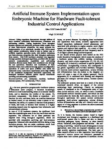
The earliest example of in-vehicle road signs only appeared in the 1990s with the introduction of GPS-based navigation systems. Digital road maps that powered such navigation devices included information about the speed limit of each road, which was displayed as a digital, in-vehicle traffic sign on the screen of the navigation device. The in-vehicle representation and the awareness of the speed sign also allowed to check the current speed of the vehicle against the enforced speed limit, warning the driver about the violation. More sophisticated in-vehicle representations of roadside traffic signs resort to vehicular sensors other than the GPS and the associated digital cartography. For example, in-vehicle radar-based systems are able to determine the distance to the preceding vehicle and warn the driver if the 2-second distance rule is violated. The ubiquity and speed-awareness of the in-vehicle approach has obvious advantages compared to the traditional representation. Windshield camera-based systems are another novel trend for the in-vehicle display of traffic signs. Such systems replace the vision sense of the driver using computer vision techniques that are able to recognize roadside traffic signs and automatically duplicate them on in-vehicle displays. Compared to mapbased systems, the computer vision approach is able to detect transitory changes on the posted speed due to, for instance, temporary road works. Computer vision in the context of vehicles has been a very active topic in ITS for the last two decades [6]. Most of the in-vehicle displaying systems for traffic signs described above are merely duplicating traffic information found on existing road signs. A recent proposal for virtualized in-vehicle traffic signs has been presented in [7], in the context of intelligent intersection control based on virtual traffic lights, solely supported by V2V communications. The basic principle is replacing physical roadside infrastructures by a temporary and virtualized infrastructure that is implemented by a stopped vehicle at the intersection. Such leading vehicle assumes the task of creating a virtual traffic light and broadcasts traffic control messages to the vehicles in the different approaches of the intersection. An interface that uses the windshield to display such virtual traffic lights was introduced in [8]. Another area where the virtualization of the windshield can already be observed is that of navigational information. In Figure 1 we display three examples of the evolution of GPS navigators. From the traditional portable navigation devices (PND) shown in frame A, the displaying of navigational information has evolved to become more embedded on the windshield, as displayed in frame C, which shows the navigational output of the new Series 5 BMW. An intermediate step is shown in frame B, displaying the innovative Blaupunkt Travel Pilot, which merges a video stream captured by a forward facing camera on the device with pictographic content created digitally, conveying navigational instruction in an augmented reality fashion. We introduced a new paradigm in the virtualization of the windshield in [5], an overtaking assistance system that superimposes the video streaming that comes from the preceding vehicle on its rear by projecting it on the windshield.
Fig. 1.
GPS navigators.
III. S YSTEM D ESCRIPTION The STS is a real-time system for providing a cooperative video-based Advanced Driver Assistance System (ADAS). Therefore, the system design was driven by safety requirements. In this section we present the system architecture and all the different elements and protocols that were implemented in the STS system.
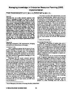
Fig. 2.
STS Architecture.
A. Architecture and protocols The STS system is comprised of three main subsystems: the unidirectional video-streaming chain, the bi-directional control module and the computer vision and human-machine interfaces. The Figure 2 shows the architecture of the STS. 1) Unidirectional video-streaming: The video-streaming chain was designed to provide low latency video streaming based on DSRC communications. Therefore, we employ the Smoke video codec that is a low latency video codec. This codec is a plug-in of the Gstreamer Linux framework [9]. The video-streaming packets must be carried in a typical RTP/UDP/IP real-time protocol stack. The Real Time Protocol (RTP) introduces timestamps that ensure timeliness of the packets. Packets that arrive beyond the delay threshold can
simply be discarded without having to be processed by the higher layers. The packets are transported over UDP/IPv6 that simply is an unreliable connectionless protocol, which has a very low overhead and does not require establishing any prior connection. The DSRC radios are equipped with a single antenna WAVE/802.11p and implement the IPv6/802.11p dualprotocol stack. The latter carries the video-streaming over one of the several 802.11p 10MHz service channels. 2) Bi-directional control module: This subsystem provides the cooperative capabilities of this ADAS system, since it is responsible for establishing the connection, monitoring the operations and assuring the safety of the takeover maneuver. The control module receives the different inputs from the vehicle sensors, the geographical and car awereness from the DSRC radio and the visual awareness from the windshield camera. After determining that all safety requirements are met, it initiates a connection with the vehicle in front and negotiates the establishment of the video-streaming connection. The vehicle in front transmits static information on the vehicle characteristics, e.g. vehicle dimensions, and but also information on the vehicle dynamics, e.g., speed, braking, acceleration. It also monitors the reliability and the timestamps of the received packets and disengages the system if the safety requirements are not met. 3) Computer vision and human-machine interfaces: These interfaces are constituted by the following elements: frontfacing windshield camera, transparent LCD monitor, dashboard interfaces. The camera has two roles: provide road signs detection; visually detect the edges of the preceding vehicle. The computer vision modules process the visual information and cue the control module relative to the detected road signs, such as speed limits or overtaking forbidden signs. Furthermore, this module also uses the vehicle dimensions information provided by the control module to match these to the image obtained with the camera in order to detect the vehicle edges. It also calculates the 3D-looking frame that provides the depth perception that matches the driver’s perspective with the camera of the vehicle in front. The incoming vehicle detection is also part of the computer vision module. Optimally, this should be located in the vehicle in front, before the video encoding in order to minimize the image noise levels. This information would be streamed in parallel with the video. The transparent LCD monitor is mounted on the windshield, allowing the video streaming image to be correctly superimposed on the driver’s field-ofview, as well as the visual bracketting information of incoming vehicles. Finally, the dashboard interfaces allows the driver to activate the STS, which could be a dedicated or multi-function button on the steering wheel. Alternatively, it could also be activated with a set of conditions, including the activation of turn signal lights. B. Communication Protocol The STS communication protocol is described in the Fig. 3. The flowchart covers all the phases of the interaction between vehicles during the overtaking maneuver. The two vehicles periodically send beacons which typically carry information with the location, heading and speed of the
Fig. 3. Flowchart describing the communication protocol between vehicles A and B.
beaconing vehicle. If the vehicle intending to overtake (A in Fig. 3) receives the “STS enabled” beacon and is within a pre-defined distance of vehicle B (for this implementation, 50 meters), then a “STS Available” sign is displayed to its driver. If the driver decides to activate the STS system, the cooperative protocol between the two vehicles is initiated, with vehicle A asking vehicle B for its relevant dimensions (length, height and width) and camera parameters (mounting point and viewing angles). Vehicle B retrieves this data to vehicle A, which then computes the best video resolution, accounting as well with the distance to vehicle B. In this implementation, the video streaming is based on two levels of resolution which are associated with two distance intervals. The degradation of the wireless links performance as a function of the inter-vehicle distance is thus balanced through a reduction on the bandwidth requirements for streaming video with a resolution that reduces as the inter-vehicle distance increases. Vehicle A then asks vehicle B for the video streaming with a specific resolution and updates this resolution request if the inter-vehicle distance changes to a different interval. During this stage of the STS protocol, vehicle B just sends the video streaming with the required resolution.
The STS communication protocol can be automatically terminated, based on the relative position and heading of the vehicles, or manually deactivated by the driver of vehicle A. C. Hardware The hardware used in the implementation of the STS comprises: • • • • • • •
2 vehicles 2 laptops 2 GPS receivers 2 DSRC radios 2 high gain antennas Mobile Mark ECOM6-5500 (56dBi) 2 high-resolution Logitech C270 webcams 1 Samsung Transparent LCD
Each vehicle is equipped with a laptop running Ubuntu Linux 12.04, a high-resolution webcam, a GPS receiver and a DSRC radio equipped with a high gain antenna. We used 802.11p compliant radios [10]. These radios implement the WAVE standard [11]. The overtaking vehicle is also equipped with a transparent LCD to provide the augmented reality apparatus needed by the STS. The preceding vehicle must be a truck or an equivalent vision-obstruction vehicle. A magnetic coloured board is attached to the rear of this vehicle, in order to its detection by the overtaking vehicle can be fast and accurate. D. Software The software implementation of the STS is designed to deliver the user with a reliable and intuitive system. Due to the nature of this system and its criticalness, we chose C++ as the main programming language. Its low memory usage, speed and the possibility to integrate with all type of frameworks, were the main choice factors. The GStreamer framework [9] was used to provide the real-time video streaming between the two vehicles. Specifically, its C++ and OpenGL plugins that make it possible to directly integrate with the rest of the software. 1) Computer Vision: Computer vision allow to correctly super-impose the video-streaming that comes from the in front vehicle over its rear. We employed the Open Source Computer Vision Library (OpenCV) [12], which provides all the functions needed to perform the vehicle detection and aims to real-time detection. As the STS needs to quickly detect the magnetic board attached to the preceding vehicle’s rear, the segmentation technique is used. Generally, the detection is done in two steps. First, we perform the color segmentation based on a predefined color range. Figure 4 displays the result of applying this technique to the frame captured by the webcam placed on the overtaking vehicle’s windshield. The white area represents the coloured areas that are within the predefined color range. Second, we detect the contours that the resulted image has, and we test if those contours match a rectangle. If a match is found, those contours are used as bounds of the 3D-looking image with the video-streaming embedded.
Fig. 4.
Image representing the color segmentation technique applied.
2) Frame Generation: The frame generation of a 3Dlooking image that merges the video with a computed frame occurs immediately after the in front vehicle has been detected. Several variables, such as inter-vehicle distance, intervehicle angles and vehicle dimensions, are used for the computation of the 3D-looking frame that will be super-imposed over the rear of the truck seen through the windshield. The description of these variables can be found in the Table I. The vehicle that intends to pursue with the overtaking maneuver is represented as vehicle A and the preceding vehicle as vehicle B. The 3D-looking image grounds on two elements: the videostreaming and the shape of the transparent tubular object. The angles α and β allow us to compute the distance at which the camera can see the road, e. Adding the computed e and the length of vehicle B, l, we can generate a tubular object with a more realistic length that reflects a more accurate distance at which the objects are captured by the camera. We can thus provide the driver with a better depth perception of the video-
TABLE I D ESCRIPTION OF THE VARIABLES USED FOR FRAMING THE VIDEO Variable (x1 , y1 ) (x2 , y2 ) d e h, l, w α β ω ρ
Description position of the driver’s eye point position of the camera distance between vehicles distance from camera to the ground capturing point height, length, width of the vehicle B horizontal view angle of the camera of the vehicle B vertical view angle of the camera of the vehicle B horizontal angle between the cameras positions vertical angle between the cameras positions
streaming transmitted by vehicle B. Furthermore, the image conveyed to the driver needs not only to give a real depth perception of the real distance of the objects in the videostreaming, but also to exhibit possible limitations that can arise from this system, such as the blind-spot. This limitation emerges as a consequence of the fact that the video-streaming only displays the view beyond the distance at which the camera starts to capture the road. Figure 5 shows the schematics of the computed image representing the 3D-looking frame on which the video-streaming is super-imposed, where we can observe two distinct visual areas. First, the outside frame that overlays the rear of the preceding vehicle. Second, the inside frame which reproduces the front view of the tubular object, by rendering the videostreaming. Using the previously calculated width/height (w0 ,h0 ) obtained by computer vision and the real width/height of the in front vehicle (w, h), we can compute the ratio between this values. (1) illustrates this computation. This ratio will continuously reflect the current distance, not only to the rear of the in front vehicle (d), but also to the camera’s ground capturing point (d + l + e). (2) and (3) reflect the computation of the inside frame (wi , hi ). Moreover, this image changes according to the relative position between the driver and the camera, given by the angles ω and ρ. This will not affect the size of both frames, it just shifts the inside frame horizontally (ω) or vertically (ρ). However, if these angles are too wide, the inside frame needs to be cropped in order to fit the outside frame. Finally, we link the correspondent vertex of each frame, resulting in a 3D-looking image that displays the video-streaming of the preceding vehicle with a realistic depth perception. r=
h h0
d0
h (d + l + e) ∗ r w wi = (d + l + e) ∗ r hi =
(1) (2) (3)
IV. E XPERIMENTATION AND VALIDATION A. Experimentation setup As the STS is focused on providing a video-based ADAS that could cause life-threatening situations, we chose to held it in a closed road in order to ensure safety while doing the
Fig. 5. Schematics of the computed image representing the 3D-looking frame on which the video-streaming is super-imposed.
experiment. This road was similar to the country roads for which this system is primarily designed to. For creating the scenarios that make possible to validate this system, several vehicles were used to simulate the normal traffic that we can find in a normal situation in this type of roads. During the experiment, the distance between the overtaking and preceding vehicles was kept within a 50 meters range. Considering the link quality between the radios, the video resolution was adjusted to ensure that all the video frames were displayed in the overtaking vehicle. All the experimentation setup parameters are described in Table II. TABLE II E XPERIMENTATION S ETUP PARAMETERS Scenario Setup Road Topology Two-way road Lanes Single Lane Road Scenario Country road Distance between vehicles ≤ 50 meters Legal speed limit 90 Km/h Preceding Vehicle Model Volkswagen Transporter Length 529 cm Width 190 cm Height 199 cm Streaming Video Codec smoke Video Resolution 640x480/340x240 Frames per second 30 Application Frame Display Frequency 30 Hz Vehicle Detection Frequency 20 Hz Position Update Frequency 1 Hz
B. Validation methodology This experimentation setup was designed not only to demonstrate the implementation of the STS but also to validate it as an efficient and reliable system. Therefore, the validation methodology focuses on achieving two goals: show that the Quality-of-Experience (QoE) of the video-streaming meets the safety requirements in terms of end-to-end delay and image quality as perceived by the driver; show that the blind spot visual representation corresponds to its physical characteristics. For the first goal, we analyze the different contributions to the end-to-end delay. Furthermore, we insert visual timestamps into the video-stream and compare them in a split screen image. We also analyze the video capture delay by recording the image of the timestamp clock and comparing it with the raw stream obtained from the camera. With this methodology, we also extend it to analyze the encoding and decoding delay of the codec, by providing a local playback of the encoded stream. For the second goal, we analyze a static and a dynamic scenario. In the static scenario, we position the vehicles on the road segment and take different photographs and screen captures in order to guarantee that the blind spot representation is accurate. In the dynamic scenario, we use an incoming vehicle to pass at different speeds, while recording the received video-stream as well as a video capture from the driver’s pointof-view. Both video-streaming have timestamps in order to measure the time that it takes an incoming vehicle to cross the blind spot. The absolute speed of the incoming vehicle must be high in order to obtain a realistic relative speed of traffic travelling in opposite road lanes. Finally, we test the system as operating in a normal road scenario and obtain the different analytical measurements as well as personal experience from using this system while driving. V. R ESULTS A. Expected results The expected results in terms of delay depend on the individual delay contributions associated to the application and network layers. 1) Application layer delay: The STS consists of several modules in which each one introduces a delay that tends to be constant. This was considered during the implementation phase. Nevertheless, both hardware and software where the STS runs will also affect the application layer delay. The frame capture delay depends on the webcam used, on the capacity of the operating system to process the raw data that comes from the device, and the performance of the library used. This delay tends to overcome the frame display delay, which depends on the frame rate of both application and monitor. Furthermore, the vehicle detection introduces a negligible delay and the application was designed to perform the detection in parallel with the frame display. Considering the overall delay, the application layer delay will be substantial, though this can be easily improved in the future with the hardware and software evolution.
2) Network delay: The WAVE/802.11p protocol stack includes the Enhanced Distributed Channel Access (EDCA) that provides a probabilistic mechanism for traffic prioritization in terms of channel access. This allows for the transmission of high-priority traffic such as real-time video-streaming in the presence of low-priority traffic. The stack also defines a Service Channel (SCH) and a Control Channel (CCH), where the latter must be monitored by all devices for exchanging safety-related data. In order to support single radio DSRC devices, it is mandatory to support channel switching between CCH and SCH, with sinchronization provided by the UTC clock from the GPS signal. Therefore, the network delay will be mostly due to channel switching, usually defined in 50ms time-slots, which bounds the channel access delay to 50-60ms, when considering all the guard times and different transmission rates. However, this assumes that all the packet queueing and scheduling mechanisms are properly implemented and that there are no other high-priority data transmissions. B. Obtained results The obtained results include the delay of both application and network layers, and the real implementation of the STS. 1) Delay: During the experimentation, the 802.11p radio devices provided a low-delay and stable transmission. The results in the Figure 6 show that we obtained a network delay of an average of 65ms during the STS activation range, 50 meters. The overall delay of the STS also comprises the application layer delay. The process of capturing a single video frame from the webcam, encoding, decoding and display such frame takes aproximately 100ms. Adding the frame display frequency (see Table II), the delay increases to 133ms. As we expected, the delay of the application layer was significant. Combining both network and application delays we have a delay near to 200ms. Nevertheless, in the worst scenario with a combined velocity of 180Km/h, the overall delay will create a visual gap of 10 meters, which for the STS is almost negligible.
Fig. 6.
Delay versus distance.
Fig. 7. STS being activated in a country road scenario. The generated frame, containing the video-streaming, super-imposes the rear of the preceding vehicle.
2) STS Implementation: The final result of the STS implementation is shown in the Figure 7. This image illustrates the process of super-imposing, on the rear of the in front vehicle, the video streaming that it transmits. We can observe the video streaming embedded in the frame generated using the method described in Section III-D2. The transparent LCD provided the best apparatus for implementing the STS. However, due to this LCD being a prototype, it lacks the ability to completely block the background, which results in a magenta tinted image as a result of the coloured panel attached to the rear of the preceding vehicle. Thus, the coloured background that appears on the image in the Fig. 7. The STS demands that the video streaming is real-time and that its quality provides the driver a perfect representation of what the preceding vehicle sees. The smoke codec of the Gstreamer framework allowed us to transmit in real-time without almost any delay (see Section V-B1). We analysed the quality of the frames received in the overtaking vehicle to ensure that the video streaming is up to the demands of this system. The peak signal-to-noise ratio (PSNR) is a simple analytical method for measuring the video quality, which provides a basic understanding of the QoE especially when the main focus in on measuring the quality in a wireless environment. Figure 8 shows the computed PSNR values between the captured and displayed video sequences. During the first 40 meters, these video sequences were almost undistinguishable (PSNR greater than 36 dB). And, between 40 and 50 meters the PSNR was above 30 dB, which corresponds to acceptable visual quality. Another issue addressed in the STS implementation was the evaluation of the blind spot that this system has. These blind spots are specially significant for long vehicles. Due to logistics, we were not able to perform the experimentation with such long vehicles. Hence, it was used a Volkswagen Transporter, which is a much smaller vision-obstruction equivalent. We created a scenario with a vision-obstruction vehicle, an overtaking vehicle and an oncoming vehicle on the opposite lane. The objective was to observe and detect the possibility of a blind spot in the STS. Considering that the blind spot occurs mostly when the distance between vehicles is reduced, the overtaking vehicle was placed a few meters behind the preceding vehicle. In the Figure 9, we can depict a small blind spot, where the oncoming vehicle does not appear on the video
Fig. 8.
PSNR versus distance.
streaming, and we can only see part of it. This blind spot would be more significant, if a longer vehicle was used as the preceding vehicle. With such vehicle, for instance a semitrailer truck, we would not be able to see the oncoming vehicle both on the video streaming and the point of view of the driver.
Fig. 9.
Blindspot generated by the STS.
VI. C ONCLUSIONS The implementation and testing of the STS in a realistic environment showed that this cooperative ADAS system performs as expected and it meets tight safety requirements. We showed that the latency introduced by the system is already quite low even when considering that several components are software-based and were not especifically designed to provide very low latency. We also showed that the augmented reality aspect of the STS is indeed representative of the overtaking scenario physical characteristics, in order to provide an intuitive driver assistance system with an actual depiction of the blind-spots. Finally, we are able to validate the STS and its implementation as a valid ADAS system that takes advantage of V2V communications to improve the safety of overtaking maneuvers by improving the visibility in the presence of large and vision-obstructing vehicles.
R EFERENCES [1] “Global status report on road safety,” 2009, http://www.who.int/violenceinjuryprevention/roadsafetystatus/2009/en/. [2] AASHTO, “Strategic Highway Safety Plan: A Comprehensive Plan to Substantially Reduce Vehicle-Related Fatalities and Injuries on the Nations Highways,” American Association of State Highway and Transportation Officials, Washington, DC, 2005. [3] T. Neuman, R. Pfefer, K. Slack, K. Hardy, H. McGee, L. Prothe, K. Eccles, and F. Council, “NCHRP Report 500: Guidance for Implementation of the AASHTO Strategic Highway Safety Plan. Volume 4: A Guide for Addressing Head-On Collisions,” Transportation Research Board of the National Academies, Washington, DC, 2003. [4] C. Olaverri-Monreal, P. Gomes, R. Fernandes, F. Vieira, and M. Ferreira, “The see-through system: A vanet-enabled assistant for overtaking maneuvers,” in Intelligent Vehicles Symposium (IV), 2010 IEEE, june 2010, pp. 123 –128. [5] P. Gomes, C. Olaverri-Monreal, and M. Ferreira, “Making vehicles transparent through v2v video streaming,” IEEE Transactions on Intelligent Transportation Systems, vol. 13, no. 2, p. 930, 2012. [6] M. Bertozzi, A. Broggi, and A. Fascioli, “Vision-based intelligent vehicles: State of the art and perspectives,” Robotics and Autonomous systems, vol. 32, no. 1, pp. 1–16, 2000. [7] M. Ferreira, R. Fernandes, H. Conceic¸a˜ o, W. Viriyasitavat, and O. Tonguz, “Self-organized traffic control,” in Proceedings of the seventh ACM international workshop on VehiculAr InterNETworking. ACM, 2010, pp. 85–90. [8] C. Olaverri-Monreal, P. Gomes, M. Kruger Silv´eria, and M. Ferreira, “Invehicle virtual traffic lights: a graphical user interface,” in CISTI’2012. IEEE, 2012. [9] “Gstreamer open source multimedia framework,” http://gstreamer.freedesktop.org/. [10] C. Ameixieira, J. Matos, R. Moreira, A. Cardote, A. Oliveira, and S. Sargento, “An ieee 802.11p/wave implementation with synchronous channel switching for seamless dual-channel access,” in Vehicular Networking Conference (VNC), 2011 IEEE, nov. 2011, pp. 214 –221. [11] “IEEE 802.11p-2010: Wireless LAN Medium Access Control (MAC) and Physical Layer (PHY) Specifications Amendment 6: Wireless Access in Vehicular Environments, IEEE Standards Association, 2010. ,” 2010. [12] “Opencv - open source computer vision library,” http://opencv.org/.