if (xk(i, j; t) = 1) ∩ (xk(i, j; t − Δt) = 1). (2). The charge value at pixel (i, j) is discharged down to vdis when no motion is detected, is saturated to vsat when motion is ...
The Underlying Formal Model of Algorithmic Lateral Inhibition in Motion Detection Jos´e Mira1 , Ana E. Delgado1 , Antonio Fern´ andez-Caballero2, 2 andez2 Mar´ıa T. L´ opez , and Miguel A. Fern´ 1
Universidad Nacional de Educaci´ on a Distancia E.T.S.I. Inform´ atica, 28040 - Madrid, Spain {jmira,adelgado}@dia.uned.es 2 Universidad de Castilla-La Mancha Instituto de Investigaci´ on en Inform´ atica (I3A) and Escuela Polit´ecnica Superior de Albacete, 02071 - Albacete, Spain {caballer,mlopez,miki}@dsi.uclm.es
Abstract. Many researchers have explored the relationship between recurrent neural networks and finite state machines. Finite state machines constitute the best characterized computational model, whereas artificial neural networks have become a very successful tool for modeling and problem solving. Recently, the neurally-inspired algorithmic lateral inhibition (ALI) method and its application to the motion detection task have been introduced. The article shows how to implement the tasks directly related to ALI in motion detection by means of a formal model described as finite state machines. Automata modeling is the first step towards real-time implementation by FPGAs and programming of ”intelligent” camera processors.
1
Introduction
Recently the algorithmic lateral inhibition (ALI) method and its application to the motion detection task have been introduced [1]-[5]. And, currently our research team is involved in implementing the method into real-time in order to provide efficient response time in visual surveillance applications [6]-[7]. In recent years, many researchers have explored the relation between discretetime recurrent neural networks and finite state machines, either by showing their computational equivalence or by training them to perform as finite state recognizers from example [8]. The relationship between discrete-time recurrent neural networks and finite state machines has very deep roots [9]-[11]. The early papers mentioned show the equivalence of these neural networks with threshold linear units, having step-like transfer functions, and some classes of finite state machines. More recently, some researchers have studied the close relationships more in detail [12]-[13], as well as the combination of connectionist and finite state models into hybrid techniques [14]-[15]. During the last decades specialized algorithms even have extracted finite state machines from the dynamics of discrete-time recurrent neural networks [16]-[19]. ´ J. Mira and J.R. Alvarez (Eds.): IWINAC 2007, Part II, LNCS 4528, pp. 119–129, 2007. c Springer-Verlag Berlin Heidelberg 2007 �
120
J. Mira et al.
The article shows how to implement the tasks directly related to ALI in motion detection and introduced by means of a formal model described finite state machines, and the subsequent implementation in hardware, as automata modeling may be considered as the first step towards real-time implementation by field programmable gate arrays (FPGAs) [20] and programming of ”intelligent” camera processors.
2
ALI in Motion Detection
The operationalization of the ALI method for the motion detection application has led to the so-called lateral interaction in accumulative computation [2],[4]. From [2],[4] we cite and reformulate the most important concepts and equations. Temporal Motion Detection firstly covers the need to segment each input image I into a preset group of gray level bands (N ), according to equation 1. � xk (i, j; t) =
1, if I(i, j; t) ∈ [ 256 N · k, 0, otherwise
256 N
· (k + 1) − 1]
(1)
This formula assigns pixel (i, j) to gray level band k. Then, the accumulated charge value related to motion detection at each input image pixel is obtained, as shown in formula 2: ⎧ v , if xk (i, j; t) = 0 ⎪ ⎨ dis vsat , if (xk (i, j; t) = 1) ∩ (xk (i, j; t − Δt) = 0) yk (i, j; t) = ⎪ ⎩ max[xk (i, j; t − Δt) − vdm , vdis ], if (xk (i, j; t) = 1) ∩ (xk (i, j; t − Δt) = 1)
(2)
The charge value at pixel (i, j) is discharged down to vdis when no motion is detected, is saturated to vsat when motion is detected at t, and, is decremented by a value vdm when motion goes on being detected in consecutive intervals t and t − Δt. Spatial-Temporal Recharging is thought to reactivate the charge values of those pixels partially loaded (charge different from vdis and vsat ) and that are directly or indirectly connected to saturated pixels (whose charge is equal to vsat ). Values zk are initialized to yk . Formula 3 explains these issues, where vrv is precisely the recharge value. ⎧ v , if zk (i, j; t + (l − 1) · Δτ ) = vdis ⎪ ⎨ dis vsat , if zk (i, j; t + (l − 1) · Δτ ) = vsat zk (i, j; t + l · Δτ ) = ⎪ ⎩ min[zk (i, j; t + (l − 1) · Δτ ) + vrv , vsat ], if vdis < zk (i, j; t + (l − 1) · Δτ ) < vsat
(3)
This step occurs in an iterative way in a different space of time τ � t. The value of Δτ will determine the number of times the mean value is calculated. Spatial-Temporal Homogenization aims in distributing the charge among all connected neighbors holding a minimum charge (greater than vdis ) - now, Ok is initialized to zk . This occurs according to the following equation.
The Underlying Formal Model of ALI in Motion Detection Ok (i, j; t + m · Δτ ) =
121
1 1 + δi−1,j + δi+1,j + δi,j−1 + δi,j+1 ×[Ok (i, j; t + (m − 1) · Δτ ) +
δi−1,j · Ok (i − 1, j; t + (m − 1) · Δτ ) + δi+1,j · Ok (i + 1, j; t + (m − 1) · Δτ ) +
(4)
δi,j−1 · Ok (i, j − 1; t + (m − 1) · Δτ ) + δi,j+1 · Ok (i, j + 1; t + (m − 1) · Δτ )] �
where ∀(α, β) ∈ [i ± 1, j ± 1], δα,β =
1, if Ok (α, β; t + (m − 1) · Δτ ) > vdis 0, otherwise
(5)
Lastly, we take the maximum value of all outputs of the k gray level bands to show the silhouette of a moving object: O(i, j; t) = arg max Ok (i, j; t) k
3
(6)
Formal Model for ALI in Motion Detection
The control knowledge is described in extensive by means of a finite automaton in which the state space is constituted from the set of distinguishable situations in the state of accumulated charge in a local memory [5]. Thus, we distinguish N + 1 states S0 , S1 , ..., SN , where S0 is the state corresponding to the totally discharged local memory (vdis ; in general vdis = 0), SN is the state of complete charge (vsat = 7) and the rest are the N − 1 intermediate charge states between vdis and vsat . Let us suppose, without loss of generality, that it is enough to distinguish eight levels of accumulated charge (N = 8) and, consequently, that we can use as a formal model of the control underlying the inferential scheme that describes the data flow corresponding to the calculation of this subtask an 8 states automaton (S0 , S1 , ..., S7 ), where S0 corresponds to vdis and S7 to vsat . Let us also suppose that discharge (vdm = 2) and recharge (vrv = 1) initially take the values corresponding to the descent of two states and to the ascent of one state. This way, the state transition diagram corresponds to a particular kind of reversible counter (“up-down”) controlled by the result of the lateral inhibition (dialogue among neighbors). To complete the description of the states, together with the accumulated charge value, v (vdis ≤ v ≤ vsat ), it is necessary to include come binary signals, AP and AC = 0, 1. When AP = 1, a pixel tells its neighbors that it has detected a mobile, or that some neighbor has told him to have detected a mobile. AC indicates that motion has been detected on the pixel. 3.1
ALI Temporal Motion Detecting
The task firstly gets as input data the values of the 256 gray level input pixels and generates N = 8 binary images, xk (i, j; t). The output space has a FIFO
122
J. Mira et al.
memory structure with two levels, one for the current value and another one for the previous instant value. Thus, for N bands, there are 2N = 16 binary values for each input pixel; at each band there is the current value xk (i, j; t) and the previous value xk (i, j; t − Δt), such that: � xk (i, j; t) =
1, if I(i, j; t) ∈ [32 · k, 32 · (k + 1) − 1] 0, otherwise
(7)
Thus, a pair of binarised values at each band, xk (i, j; t) and xk (i, j; t − Δt), constitutes the input space of the temporal non recurrent ALI. The output space is the result of the individual calculus phase in each calculus element. The inputs are observables xk (i, j; t) and xk (i, j; t − Δt) and the current charge value that initially is at state S0 . It also receives the comparison rule and the numerical coding of the different discrepancy classes (D1, D2, D3). The output is the class of discrepancy selected at this time, D(t). ⎧ ⎨ D2, if (xk (i, j; t) = 1) ∩ (xk (i, j; t − Δt) = 0) D3, if (xk (i, j; t) = 1) ∩ (xk (i, j; t − Δt) = 1) D(t) = ⎩ D1, otherwise
(8)
This class is now an input in charge of filtering a specific charge value (before dialogue) from a set of potential values. These potential values are vdis , vsat and max[xk (i, j; t − Δt) − vdm , vdis ]. The output of subtask ALI Temporal Motion Detecting constitutes the accumulated charge value, yk (i, j; t), complemented by label AC . Remember that AC = 1 denotes the fact that a movement has been locally detected by this pixel. � AC =
1, if D(t) = D2 0, otherwise
⎧ if D(t) = D1 ⎨ vdis , if D(t) = D2 vsat , yk (i, j; t) = ⎩ max[x (i, j; t − Δt) − v , v ], if D(t) = D3 k dm dis
(9)
(10)
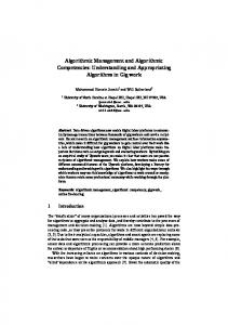
The following situations can be observed in Fig. 1 (see discrepancy class D): 1. xk (i, j; t − Δt) = 0, 1, xk (i, j; t) = 0 (corresponding to discrepancy class D1) In this case the calculation element (i, j) has not detected any contrast with respect to the input of a mobile in that band (xk (i, j; t) = 0). It may have detected it (or not) in the previous interval (xk (i, j; t − Δt) = 1, xk (i, j; t) = 0). In any case, the element passes to state S0 [v = vdis , AC = 0], the state of complete discharge, independently of which was the initial state. 2. xk (i, j; t − Δt) = 0, xk (i, j; t) = 1 (corresponding to discrepancy class D2) The calculation element has detected in t a contrast in its band (xk (i, j; t) = 1), and it did not in the previous interval (xk (i, j; t − Δt) = 0). It passes to state S7 [v = vsat , AC = 1], the state of total charge, independently of which was the previous state. Also AC passes to 1, in order to tell its potential dialogue neighbors that this pixel has detected a mobile. 3. xk (i, j; t − Δt) = 1, xk (i, j; t) = 1 (corresponding to discrepancy class D3). The calculation element has detected the presence of an object in its band (xk (i, j; t) = 1), and it had also detected it in the previous interval (xk (i, j; t − Δt) = 1). In this case, it diminishes its charge value
The Underlying Formal Model of ALI in Motion Detection 01
123
TOTAL CHARGE
S0 [vdis, AC=0]
S7 [vsat, AC=1]
00,10 10 TOTAL DISCHARGE 10
PARTIAL DISCHARGE
Sint [vint, AC(t)]
11
11
Fig. 1. Control automaton that receives inputs xk (i, j; t − Δt) and xk (i, j; t), and produces three outputs, coincident with its three distinguishable charge states (S0 = vdis , S7 = vsat , and vint )
in a certain value, vdm . This discharge - partial discharge - can proceed from an initial state of saturation S7 [vsat , AC = 1], or from some intermediate state (S6 , ..., S1 ). This partial discharge due to the persistence of the object in that position and in that band, is described by means of a transition from S7 to an intermediate state, Sint [vint , AC = 0, 1], without arriving to the discharge, S0 [vdis , AC = 0]. The descent in the element’s state is equivalent to the descent in the pixel’s charge, such that (as you may appreciate on Fig. 1) only the following transitions are allowed: S7 → S5 , S6 → S4 , S5 → S3 , S4 → S2 , S3 → S1 , S2 → S0 , and S1 → S0 . 3.2
ALI Spatial-Temporal Recharging
In the previous task the individual “opinion” of each computation element has been obtained. But, our aim is also to consider the “opinions” of the neighbors. The reason is that an element individually should stop paying attention to motion detected in the past, but before making that decision there has to be a communication in form of lateral inhibition with its neighbors to see if any of them is in state S7 (vsat , maximum charge). Otherwise, it will be discharging down to S0 (vdis , minimum charge), because that pixel is not bound to a pixel that has detected motion. The output is formed after dialogue processing with neighboring pixels by the so called permanency value, zk (i, j; t). The values of charge accumulated before dialogue are written in the central part of the output space of each pixel (C ∗ ) that now enters in the dialogue phase. The data in the periphery of receptive field in the output space of each pixel (P ∗ ) contains now the individual calculi of the neighbors. Let vC (t) = yk (i, j; t) be the initial charge value at this subtask. Each pixel takes into account the set of individual calculus, vC (t + k · Δτ ), Aj , by means of the logical union of the labels: AP ∗ (τ ) =
� j
Aj (τ )
(11)
124
J. Mira et al.
This result, AP ∗ , is now compared with AC , giving rise to one of two discrepancy classes (recharge or stand-by). D(t + l · Δτ ) =
⎧ ⎨ stand − by(vdis ), if vC (t + l · Δτ ) = vdis stand − by(vsat ), if vC (t + l · Δτ ) = vsat ⎩ recharge, if (v dis < vC (t + l · Δτ ) < vsat ) ∩ (AP ∗ = 1)
(12)
Subsequently, the class activated plays the role of selection criteria to output the new consensus charge value after dialogue, zk (i, j; t + Δt), with Δt = k · Δτ , being k the number of iterations in the dialogue phase, a function of the size of the receptive field. Notice that τ is a parameter that only depends on the size of the objects we want to detect from their motion. So, the purpose of this inference is to fix a minimum object size in each gray level band. The whole dialogue process is executed with clock τ , during k intervals Δτ . It starts when clock t detects the configuration yk (i, j; t − Δt) = yk (i, j; t) = 1 and ends at the end of t, when a new image appears. � AC =
1, if D(t + l · Δτ ) = {stand − by(vsat ) ∪ recharge} 0, otherwise
(13)
⎧ v , if D(t + l · Δτ ) = stand − by(vdis ) ⎪ ⎨ dis vsat , if D(t + l · Δτ ) = stand − by(vsat ) v(t + l · Δτ ) = ⎪ ⎩ min[v(t + (l − 1) · Δτ ) + vrv , vsat ], if (D(t + l · Δτ ) = recharge
(14)
AC = 0, if D(t + (l − 1) · Δτ ) = {stand − by(vsat ) ∪ recharge}
(15)
In each dialogue phase (in other words, in each interval of clock Δτ ), the calculation element only takes into account values yk (i, j; t − Δt), yk (i, j; t) and AC (t) present in that moment in its receptive field. To diffuse or to use more distant information, new dialogue phases are necessary. That is to say, new inhibitions in l · Δτ (1 < l ≤ k) are required. This only affects to state variable AC (τ ), as yk (i, j; t − Δt) and yk (i, j; t) values remain constant during the intervals used to diffuse τ and to consensus the different partial results obtained by the calculation elements. Notice that the recharge may only be performed once during the whole dialogue phase. That is why AC = 0, when a recharge takes place. Lastly, the output will be: zk (i, j; t + Δt) = vC (t + Δt)
(16)
In the corresponding state transition diagram the following situations have to be distinguished: 1. yk (i, j; t − Δt) = 0, 1, yk (i, j; t) = 0 In any case, independently of the pixel’s dialogue with the neighbors, at the end of Δt the pixel passes to state S0 [v = vdis , AC = 0]. 2. yk (i, j; t − Δt) = 0, yk (i, j; t) = 1 Again, independently of the dialogue phase, the pixel’s state will be S7 [v = vsat , AC = 1]. 3. yk (i, j; t − Δt) = 1, yk (i, j; t) = 1 (a) Local memory is in S0 [vdis , AC = 0]. Pixels in state S0 are not affected by lateral recharge due motion detection in their periphery. Thus, the pixel maintains the same state S0 .
The Underlying Formal Model of ALI in Motion Detection
125
IJ