create a global deformable or rigid object, this property and its inverse, i.e. .... of a behavioral animation, it is almost impossible (as in a theatrical scene) to.
THE USE OF FINITE ELEMENT THEORY FOR SIMULATING OBJECT AND HUMAN BODY DEFORMATIONS AND CONTACTS
Jean-Paul Gourret MIRALab, University of Montreal, Canada Nadia Magnenat-Thalmann MIRALab, Centre Universitaire d'Informatique CH 1207 Geneva, Switzerland Daniel Thalmann Computer Graphics Lab. Swiss Federal Institute of Technology CH 1015 Lausanne, Switzerland
This paper presents a method for combining image synthesis and modeling based on a finite element method (FEM) to get realistic intelligent images. FEM is used for modeling both elastically and plastically deformations of objects, and impacts with or without penetration between deformable objects. The concept of deformable objects is applied to human flesh to improve the behavior of synthetic human grasping and walking. The paper also discusses the introduction of this method in an animation system based on the concept of "intelligent" synthetic actors with automatic motion control performed using A.I. and robotics techniques. In particular, motion is planned at a task level and computed using physical laws.
1. INTRODUCTION More realism and interactivity in flight simulators, land vehicle simulators, and 3D animation in computational science or advertising, are among the goals of Scientific Visualization [1]. The pilot trainee, scientist or designer must be considered as both an actor and an animator. He or she must be fully involved in the scene being visualized or created, and must be able to control the simulated environment or a part of it. Image modeling can help to improve scene understanding in the same way that modeling can help measurement interpretation. For example, in the modeling of semiconductor devices, surface charges can be estimated based on a correct modelling of volume and surface properties of materials [2]. This type of measure is attractive because it does not disturb the component. With images generated using numerical methods for solving the physical equations, it is possible to compare the results to the reality. This approach is interesting in moving scene analysis or in robotics environment for predictions.
the notion of control must be extended to the realistic and automatic displacement of bones and skin. Image processing is a classical way for scene improvement and understanding. Basic 2D digital image processing is used in many fields, based on a few basic algorithms working in space or frequency domain [3]. In scanner imagery, 2D slices of pixels are combined to build a voxel-based cube. Improvements of these 3D images are performed using 3D digital image processing algorithms [4] and permit display of surfaces from volume data made of mixed materials. Voxels architectures for visualization of these 3D data are also studied [5]. A package combining 3D image processing, 3D image synthesis and 3D image modeling would be a essential tool for actor-animators, as defined earlier. Combination would permit digital image processing of virtual images to be compared with image processed from reality, or virtual image calculations to be compared with reality. Problems of contact modeling [6] combined with flight simulator tools or forces transducers with retroactive feedback used in computer animation [7] would be also of great interest in telemanipulation modeling for design of a person-computer interface. For this purpose, virtual experimentation should incorporate person in modeling. In this paper, we give a possible method for combining image synthesis and image modeling to get intelligent images. It is based on finite element theory to model both the shape of objects in agreement with physical laws, and the deformations of human flesh resulting from contact with objects. The following two arguments support the use of the same method for modeling the deformation of objects and human flesh. First, we want to develop a method which will be able to deal with penetrating impacts and true contacts. Simulation of impact with penetration can be used to model the grasping of ductile objects or to model ballistic problems, and needs decomposition of objects into small geometrically simple objects. Second, when a deformable object is in contact with human body, we expect reacting forces resulting from deformation of object and flesh provide significant information about the object and more generally about the environment of the synthetic human body. The contact problem involved in a grasping task is described in another paper [6]. The exchange of information using acting and reacting forces is significant for a realistic grip and can influence the behavior of the skeleton. For grip, interacting information is as important as that supplied by tactile sensors in a robot manipulator. This is a well known, yet unresolved, problem of robotics called "compliant motion control" which consists of taking into account the external force values to command the joints and links of the fingers using inverse kinematic or dynamic controls. Formerly, authors dealing with kinematic and dynamic animation models oriented to automatic animation control [8] [ 9] [ 10] [ 11], have often referred to works in robotics [12] [ 13] [ 14]. In the same way, we believe that CAD methods may be used to improve synthetic human animation control.
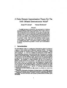
In this paper, we do not describe the theory of finite element analysis. A comprehensive study of the finite element theory is given in Bathe [15] and Zienkiewicz [ 16]. A summary of the theory of elasticity can be found in Timoshenko and Goodier [17]. Two characteristics of FEM are interesting in computer animation and will be described in the next sections. 2.1 Compatibility of FEM with visual realism Three-dimensional object shapes are defined using simple or complex volume elements which ensure zero order continuity between vertices. As with surface patches, it is possible to ensure a higher order continuity between elements. However, this procedure is expensive in terms of memory space and CPU time. So, our calculations are based on linear elements with zero order continuity. However, the use of complex elements and continuity of higher order allows to get the same visual effects than surface patches. Indeed, elements in FEM are parametric volumes (called reference volumes) and the boundary object surface in an image synthesis system is a parametric surface.
Fig.1 a. linear element with zero order continuity (polygon-based surface) b. cubic element with zero order continuity (Coons surface) c. cubic element with zero order continuity (Coons surface with Hermite interpolation polynomials) So, when an element flushes an object surface, it leads to the same realism obtained with an image synthesis system. We show in Figure 1 assemblages of linear elements with zero order continuity, cubic element with zero order continuity and cubic element with first order continuity.
In the HUMAN FACTORY system, objects and envelop of human body are defined with polygons. To keep the compatibility with the image synthesis system, we use linear elements with zero order continuity. Our three-dimensional model uses elements with eight nodes and NOF = 3 degrees of freedom by node. These elements can be easily modified to prismatic or tetrahedral elements to approximate most existing 3D shapes. The composition of NBEL elements with 8 points give NBP points and NB = NBP*NOF equations.
2.2 Decomposition of a global deformable object into two or multiple sub-objects Since the process used in the finite element method consists of a composition of elements to create a global deformable or rigid object, this property and its inverse, i.e. decomposition of a global deformable object into two or multiple sub-objects, should be used in computer animation. The decomposition is very easy to implement because in the numerical method the constitutive properties of each element and inter element forces are memorized and are taken into account during calculations. It is possible for example to create a global object constituted of different sub-objects, each sub-object having its own constitutive properties and being constituted by one or more elements. There are several ways to exploit the intrinsic properties of the finite element method: - The decomposition approach can be exploited for modeling penetrating shocks between two or more deformable objects. Each object is subdivided in many deformable sub-objects able themselves to interact each other in their turn because each of them brought with him its own properties. - The composition approach can be used for modeling contacts without penetration between two or more objects. Here, objects can be considered as sub-objects evolving independently until a contact is detected and a global object is composed after contact. This process works if we consider the contact forces, that prevent overlapping, into the problem [18]. However, these non linear effects are not so easy to implement. As pointed out by Terzopoulos and Witkin [19] non linear formulation can lead to difficulties in the numerical implementation. Even if an efficient FEM code, developed for CAD, is available, problems can happen or can greatly increase the computational time. We used a formulation in small strains, a classical engineering stress measure (Cauchy stress) and a linear constitutive law. The relation between internal stresses and strains in the Hooke law [19] that is applicable in small strains because Poisson's modulus and Young's modulus which define it are only valid for small deformations. This formulation is simple but gives; good visual results without necessitating long calculations. In computer animation, visual effects must often be emphasized. Large displacements, rotations and strains must be modeled. When force is acting on the top of an object, inflation of the edges
the object, but edges stay unchanged. Among non linear inelastic materials, the modeling of elasto-plasticity is important for the simulation of penetrating contacts. This type of material does not return to the rest position if a critical internal stress threshold is overrun.
3. EXAMPLE OF CONTACTS To show how the physical modeling of deformable objects can contribute to human animation, we present in this section an example of a contact problem dealing with the pressing of a ball. Starting with the envelopes of ball and fingers obtained using SABRINA [21], we meshed the objects to create full 3D bodies or shell bodies depending on the application. After 3D finite element solving, the deformed envelopes are extracted from the data base used in our calculations and restored to SABRINA for visualization. In this way, visual realism is always ensured by the image synthesis system. The ball can be modeled by a shell with internal pressure, or can be fully meshed in its volume. Figure 2 shows component elements and nodal points of a ball.
Fig. 2 Component elements Fig.3. Finger tissue and bones and nodal points of the ball Figure 3 shows a finger used in our calculations. The finger tissue is meshed in a volume around the bones. Bones are connected to the link and joint skeleton and the degrees of freedom of nodal points situated on bones are prescribed. A more realistic skeleton associated with hand envelope is shown in Figure 4. The hand is presented at rest, joint articulations of bones can be linked to hand skeleton segments as defined by Magnenat-Thalmann et al.[22].
Fig. 4. Hand and bones Relation (6) of appendix is valid in static equilibrium and in pseudo-static equilibrium at instants ti. Instants ti are considered as variables which represent different load intensities. In this paper, we do not deal with dynamics when loads are applied rapidly. Here, true time, inertia and damping, displacement velocity and acceleration must be added to (6). Contact modeling is not easy because the equilibrium equations (6) are obtained on the assumption that the boundary conditions stay unchanged during each time ti. Two kinds of boundary conditions exist: geometric boundary conditions corresponding to prescribed displacements, and force boundary conditions corresponding to prescribed boundary tractions. We cannot control a single degree of freedom in both position and force, no more than one can specify both voltage and current across a resistor. So, the unknown displacement will correspond to known prescribed force and conversely known prescribed displacement will correspond to unknown force. Boundary conditions can change during grasping and pressing when the prescribed forces Rk are enough significant to strongly deform the ball. This situation creates other contact points. So, the calculations are more complicated because the number of unknown displacements Uu and reacting forces Ru will vary depending on the number of contact points which prescribe Rk. We show in Figure 5 the surface contact appearance between a finger and a ball. Ball nodes are always maintained outside the finger. The overlap suppression creates reaction forces on the ball surface, which are applied to the skin. At equilibrium, these forces maintain compatible surface
finger
A D
B
E
C
ball ball node A,B,C are ball nodes repelled on surface finger finger node
D,E are finger nodes inside the ball
Fig.5 surface contact appearance between a finger and a ball
4.
THE ROLE OF FINITE-ELEMENT-BASED ANIMATION SYSTEM
DEFORMATIONS
IN
THE
4.1 Animation of human beings conscious of their environment This research is part of a large project dedicated to the development of an integrated animation system for the creation and animation of three-dimensional scenes involving human beings conscious of their environment. Such a system should be based on an interdisciplinary approach and integrate aspects and methods from animation, mechanics, robotics, physiology, psychology, and artificial intelligence. The system should complete the following goals: - automatically produce computer-generated human beings with natural behavior - improve the complexity and the realism of motion; realism of motion needs being improved not only from the joint point-of-view as for robots, but also in relation to the deformations of bodies, hands and faces during animation. - reduce the complexity of motion description The first part of the project, developed at MIRALab, University of Montreal was the HUMAN FACTORY System [23] [24], which allows users to recreate any human being in any setting by giving certain commands to the computer. This system led to the production of the films Eglantine and Rendez-vous à Montréal. Rendez-vous à Montréal is a seven-minute film which brings Marilyn Monroe and Humphrey Bogart back to life. It was produced for celebrating 100 years of engineering in Canada. In the second part of the project, the animation system is based on the concept of "intelligent" synthetic actors [25]. Motion control is automatically performed using A.I. and robotics techniques. In particular, motion is planned at a task level and computed using physical laws. In such a system there are five steps to automatic motion control: Step 1: positional constraints and inverse kinematics In a typical animation system based on inverse kinematics, the animator specifies discrete positions and motions for end parts; then the system computes the necessary joint angles and orientations for other parts of the body to put the specified parts in the wished positions and through the wished motions. To make a synthetic actor sit down on a chair, for example, it is necessary to specify the relevant constraints on the feet, on the pelvis and on the hands. A simple algorithm solving the positional constraint problem has been implemented in our system [26]. The animator may impose constraints at the hands, the feet and the pelvis levels. The position and orientation of the hand or the feet may be specified in the local coordinate system attached to the limb, or in the actor system or the world system. A constraint may be a fixed position/orientation or a 6D trajectory. Tools are available for building constraints as functions of the actor environment and his envelop. Step 2: motion control using dynamics A more complex, but more realistic approach is based on dynamics. The motion of a synthetic actor is governed by forces and torques applied to limbs. Our mechanical approach [27] treats open and closed chains indifferently and it is based on the principle of virtual work [28]. To save a lot of CPU time, most calculations (Jacobian matrix) are performed using a symbolical way in
Step 3: impact of the environment Adaptive motion control of an actor means that the environment has an impact on the actor motion and conversely. Informations about the environment and the actor must be available during the control process. The purpose of adaptive control motion is to decrease the amount of information entered into the computer by the animator. This is done by using existing informations about the scene and the actor. The system should also have an efficient representation of the geometry of the objects to automatically plan tasks and prevent collisions. We are currently work on the problem of walking without collision among obstacles. A 2D trajectory for the actor is obtained by projecting the octagonal cylinders surrounding the obstacles on the floor and building the visibility graph using the Lozano-Perez algorithm [29]. Then, the obstacles are grown according to a selected projection of the actor. The result trajectory is then used as input to a positional constraint solver based on inverse kinematics. As already discussed at the beginning of this paper, when a deformable object is in contact with human body, we expect reacting forces resulting from deformation of object and flesh provide significant information about the object and more generally about the environment of the synthetic human body. This is a typical case of impact of environment. The way of introducing this into the animation system is discussed in the next section. Step 4: task planning Task planning is a major problem in robotics and artificial intelligence. The problem complexity is directly dependent on the generality of the actor micro world. Given a task description, the problem consists of decomposing the task in a sequence of elementary movements. In our new animation system, three kinds of tasks will be supported: walking: To generate the motion corresponding to the task "WALK from A to B", the task-level system should integrate the following elements: obstacle avoidance, locomotion on rough terrains, trajectory planning, kinematics and dynamics. grasping: To generate the motion corresponding to the task "PICK UP the object A and PUT it on the object B", the task-level system should integrate the following elements: path planning, obstacle avoidance, stability and contact determination, deformations because of contacts (FEM), kinematics and dynamics. talking: To generate the motion corresponding to the task "SAY THE SENTENCE s ", the task-level system should integrate the following elements: phonemes detection, choice of facial expression selections, handling of facial parameters, animation generation. Step 5: behavioral animation Behavioral animation [30] corresponds to modeling the behavior of characters, from a path planning to complex emotional interactions between characters. The animator is responsible for the design of these behaviors; " his job is somewhat like a theatrical director: the character's performance is the indirect result of the director's instructions to the actor." Because of the personality of the character, his reactions may sometimes make surprises. In an ideal implementation of a behavioral animation, it is almost impossible (as in a theatrical scene) to exactly play the same scene twice. You cannot walk exactly the same way from the same bar to home twice. One current experiment is the design of an animation scene consisting of a small group of people walking together. The problem mainly consists of finding trajectories and using them as inputs to a positional constraint solver based on inverse kinematics.
This section briefly discusses how animation of deformable objects and human bodies has been added to the HUMAN FACTORY system. For animation of rigid objects, the HUMAN FACTORY system already contained animation procedures for simple physical movements applied to material points, such as movement of pendulum, circular movement with acceleration, projectile with initial velocity and basic animation laws. These physical or empirical laws were applied to animated variables or state variables. In this way, during the specified interval, state variables were automatically updated to the next value according to the evolution law [31]. Moreover, these state variables drive actor transformations. Association of state variables and actor transformations allows a complex animation of actors. Animation of a physically deformable object are simply supported in the HUMAN FACTORY system by defining prescribed displacements called Uk in the preceding sections as new state variables. When the three degrees of freedom of a point are prescribed, state variables of VECTOR type are enough to define the movement of prescribed points. When less than three degrees of freedom are prescribed, a new type of state variable has been defined. With such an approach deformable bodies are processed as actors. Object points are not only submitted to translations and rotations but automatically follow the prescribed degrees of freedom according to their constitutive law and other potential constraints such as body forces and surface forces. In the HUMAN FACTORY system, the skeleton is made up of rigid segments linked at joints and the skeleton animation is based on joint angle definition. With our numerical approach, a realistic skeleton can be linked to skeleton segments and prescribed degrees of freedom can be fixed on bone surfaces. Without environmental contact, prescribed degrees of freedom must be displacement U k. When a contact is realized these same prescribed degrees of freedom must be forces Rk and displacements are driven by contact forces.
CONCLUSION A finite element method in three dimensions has been introduced to model both object deformations and synthetic human flesh deformations. By doing this, the method gives information about the synthetic environment of the human. This environment is made up of physical objects, which should act as it would if they had a mind. They should react to applied forces such as gravity, pressure and contact. This approach provides a significant contribution to automatic motion control in 3D character animation. We believe that it can be used to improve the behavior of human grasp and human gait and more generally to improve synthetic human behavior in the synthetic environment.
ACKNOWLEDGMENTS The research was supported by the Natural Sciences and Engineering Council of Canada, the FCAR foundation, le Fonds National Suisse pour la Recherche Scientifique and the Institut National de la Recherche en Informatique et Automatique (France).
REFERENCES
3 4
5
6
7
8
9
10
11
12
13
14
15 16 17
18
19
20
21
22
23
24
25
26
Gonzales and Wintz, Digital Image processing, Wyley, 1986 Drebin R.A., Carpenter, L., and Hanrahan, P., Volume Rendering, Proc. SIGGRAPH '88, pp.65-74 Kaufman, A. and Bakalash R., Memory and Processing Architecture for 3D Voxel-based imagery, IEEE Computer Graphics and Applications, Nov. 1988, pp.10-23. Gourret, J.P., Magnenat Thalmann, N. and Thalmann, D. Simulation of Object and Human Skin Deformations in a Grasping Task, Proc. SIGGRAPH '89 Luciani A. Un outil informatique de création d'images animées: modèles d'objets, langage, controle gestuel en temps réel. Le système ANIMA. These Docteur-Ing. INP Grenoble 1985 Wilhelms, J., Toward automatic motion control, IEEE Computer Graphics and applications, Vol 7 No 4, pp 11-22 Armstrong, W.W. and Green, M.W., The dynamics of articulated rigid bodies for purpose of animation, The Visual Computer, Vol 1 (1985) pp 231-240 Calvert, T.W., Chapman, J. and Patla, A., Aspects of the kinematic simulation of human movement, IEEE Computer Graphics and applications, (nov 1982) pp 41-52 Zeltzer, D., Motor control techniques for figure animation, IEEE Computer Graphics and Applications, Vol 2 No 9 (1982) pp 53-59 Paul, R.P., Robot manipulators: mathematics, programming and control, The MIT Press, Cambridge, Mass., (1981) Lee, C.S.G., Gonzales, R.C. and Fu, K.S., Tutorial on robotics, IEEE Comp. Soc. Press, Silver Spring, Md, (1983) Hollerbach, J.M., A recursive Lagrangian formulation of manipulator dynamics and a comparative study of dynamics formulation, IEEE Trans. on systems, man and cyber., SMC10 No 11 (1980) pp 730-736 Bathe, K.J. "Finite element procedures in engineering analysis", Prentice Hall, Inc., (1982) Zienkiewicz, O.C., The finite element method, Third edition, McGraw-Hill, London, (1977) Timoshenko, S. and Goodier, J.N., Theory of elasticity, 3rd. ed., Mc Graw-Hill Book Company, New-York, (1970) Bohm, J., A comparison of different contact algorithms with applications, Comp. Structures, Vol 26 No 1-2 pp 207-221 (1987) Terzopoulos, D. and Witkin, A., Physically-based models with rigid and deformable components, Proc. Graphics Interface '88, pp.146-154 Peeken, H., Dopper, R., Orschall, B., A 3D rubber material model verified in a user-supplied subroutine, Comp. Structures, Vol 26 No 1-2 pp 181-189 (1987) Magnenat-Thalmann, N. and Thalmann, D., Image synthesis: Theory and Practice, Springer, Tokyo, (1987) Magnenat-Thalmann, N., Laperrière, R. and Thalmann, D., Joint-Dependent Local Deformations for Hand Animation and Object Grasping, Proc. Graphics Interface '88, Edmonton, Canada Magnenat-Thalmann N, Thalmann D (1983) The Direction of Synthetic Actors in the film Rendez-vous à Montréal, IEEE Computer Graphics and Applications, Vol. 7, No 12 Magnenat-Thalmann N, Thalmann D, Construction and Animation of a Synthetic Actress, Proc. EUROGRAPHICS '88, Nice, France, 1988, pp. 55-66. Thalmann, D., Magnenat Thalmann, N., Wyvill, B. and Zeltzer, D., Synthetic actors: the Impact of A.I. and Robotics on Animation, SIGGRAPH '88 Course Notes. Boisvert D, Magnenat-Thalmann N, Thalmann D (1989) An Integrated View of Synthetic Actors, Proc. Computer Graphics International '89, Springer, Tokyo
28
29
30
31
Arnaldi B (1988) Conception du Noyau d'un Système d'Animation de Scènes 3D intégrant les Lois de la Mécanique, PhD thesis, University of Rennes I Lozano-Perez T and Wesley MA (1979) An Algorithm for Planning Collision-Free Paths Among Polyhedral Obstacles, Comm.ACM, Vol.22, No10, pp. 560-570. Reynolds C (1987) Flocks, Herds, and Schools: A Distributed Behavioral Model, Proc.SIGGRAPH '87, Computer Graphics, Vol.21, No4, pp.25-34 Magnenat-Thalmann N and Thalmann D. 3D Computer Animation: More an Evolution Problem than a Motion Problem, IEEE Computer Graphics and Applications, Vol. 5, No 10, 1985, pp.47-57.
APPENDIX Following Bathe [17], we give the main relations used in implementation of the finite element method. Vectors are underlined once and matrices twice. The principle of virtual displacements applied to a continuum body states that at equilibrium, the internal virtual work is equal to the external virtual work. ⌠ ⌡εTτ dV = ⌠ ⌡ uT fb dV + ⌠ ⌡ usT fs dS + ∑ uiT Fi V
where:
V
S
(1)
i
ε is the strain vector corresponding to virtual displacements u τ is the stress vector corresponding to strains fs are surface tractions fb are body forces Fi are concentrated forces V and S are volume and surface of the body where forces are acting.
The equilibrium relation (1) can be written for each particle or element of the continuum body and the whole body is obtained by composing all elements: ⌠ ε T τ dV NBEL ⌡ e e e el=1 Ve ∑
=
⌠ u T f dV NBEL ⌡ e Be e el=1 Ve ∑
+
⌠ u T f dS NBEL⌡ Se Se e el=1 VSe ∑
NBP
+
∑ uiT Fi
(2)
node=1
where Ve and Se are volume and surface of each element. For each element we can define - a discretization ue = H _e U where H _ e is an interpolation function and U is the displacement at nodes.
(3)
τe = C _ e εe
(4)
- a relation between internal strains and displacements εe = B _e U
(5)
Using relations (3),(4) and (5) in (2) we get the relation K _ U=R
(6)
where K _ is the [NB*NB] stiffness matrix, a function of material and flesh constitution, R is the [NB*1] load vector including the effects of the body forces, surface tractions and initial stresses, and U is the [NB*1] displacement vector from the unloaded configuration. In dynamic treatment, not used in images in this paper, relation (6) becomes .. . M U + D U (7) _ _ +M _ U= R .. . where U and U are respectively nodal points velocity and acceleration, M _ is the mass matrix ⌠ ⌡Η M _ = NBEL _ eT ρeΗ _ eI dVe el=1 ∑
(8)
Ve
ρe is the mass density of each element, D _ is the damping matrix ⌠Η ⌡ D _ = NBEL _ eT deΗ _ e dVe el=1 ∑
(9)
Ve
de is the damping property of each element. Time integration of (9) can use explicit method of resolution as central difference or implicit method as Newmark's method.