scheme for microgrids based on a suitable designed third-order sliding mode ...... chattering-free second-order sliding mode control,â IEEE Trans. Au- tomat.
Third Order Sliding Mode Voltage Control in Microgrids Michele Cucuzzella, Gian Paolo Incremona and Antonella Ferrara
Abstract— In this paper, we propose a robust voltage control scheme for microgrids based on a suitable designed third-order sliding mode (3-SM) controller. The use of 3-SM allows to reject matched disturbances and unmodeled dynamics, due to the presence of a voltage-sourced-converter (VSC) as interface with the main grid. The motivation for using a 3-SM control approach, apart from its property of providing robustness to the scheme in front of a significant class of uncertainties, is also given by its capability of enforcing sliding modes of the controlled system with chattering alleviation. The microgrid system controlled via the proposed 3-SM approach proves to exhibit appreciable stability properties. Specifically, the voltage error with respect to the required reference is steered to zero in a finite time. The comparison with respect to second order sliding mode (SOSM) and PI controllers shows the beneficial effects of the proposed strategy, and simulation results confirm that our control law provides closed-loop performance complying with the IEEE recommendations for power systems.
I. I NTRODUCTION Nowadays, the continuously growing demand of energy and the need of efficient power plants for a sustainable generation and distribution have caused the diffusion of the concept of “smart grid” [1]. A smart grid is an advanced networked system with some intelligent capabilities in terms of energy generation and metering, so as to manage electricity demand and distribution in an efficient and economically convenient manner. The key-point of a smart-grid is the widely use of renewable energy sources, which are geographically distributed and produce several beneficial effects in terms of reduction of carbon dioxide emissions and pollutants. The introduction of smart grid implies a significant renovation of the current electrical system, which would present several distributed generation units (DGus), each one able to independently fulfill the owner energy demand, while guaranteeing the requirements imposed by the integration with the main grid [2]–[5]. Note that, a set of multiple mutual connected DGus is regarded as a “microgrid” in the literature [6]–[8]. Moreover, the discontinuous nature of renewable energy sources makes mandatory the introduction of robust control strategies to regulate voltage, fault detection, reliability, and power losses, which are among the issues to solve in order to integrate DGus into the distribution network [9]. In the literature, several control strategies have been proposed to stabilize a DGu in spite of the presence of some uncertainties. The majority of them use traditional PI controllers and integral oscillators to control the voltage and the frequency in the socalled islanded operation mode (IOM) [10]–[12]. Furthermore, This is the final version of the accepted paper submitted for inclusion in the Proceedings of the European Control Conference, Jul., 2015.
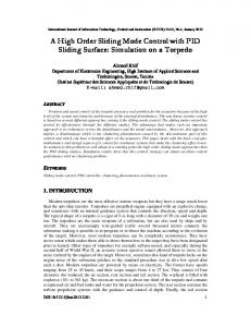
master-slave configurations [12] and Plug-and-Play (PnP) decentralized algorithms [13] have been proposed to manage the generation in a large scalable meshed microgrid. One of the crucial problems in DGus is the presence of the voltage-sourced-converter (VSC) as interface with the main grid. The VSC can be viewed as a source of modelling uncertainty and disturbances. This fact makes the adoption of a robust control design methodology mandatory. Sliding mode (SM) control [14], [15] is a very well-known control approach, particularly appreciated for its robustness properties. Yet, SM control requires the use of discontinuous control laws, which can enforce the so-called chattering effect [16]–[18]. An effective way to perform chattering alleviation is to increase the order of the sliding mode enforced by the controller. This is the reason why higher order sliding mode (HOSM) controllers [19], and, in particular, second order sliding mode (SOSM) controllers [20]–[23] have been developed in the last two decades. In this paper, a model of a DGu is first formulated. It is observed that its natural relative degree is equal to 2. Thus, the use of 3-SM control is proposed to obtain, at the same time disturbance rejection, robustness versus matched uncertainty and chattering alleviation. The validation and verification of the proposed approach have been carried out in simulation, relying on a model of a microgrid in IOM with three DGus in a master-slave configuration. Satisfactory performances have been obtained by the comparison of 3-SM with respect to a SOSM controller and a PI traditional controller. Note that the use of SOSM control laws to solve the control problem in question has been addressed in details in [24]. The present paper is organized as follows. In Section II the DGu architecture is introduced, while in Section III the control problem is formulated. The proposed 3-SM control strategy is reported in Section IV, while the stability analysis is discussed in Section V. Simulation results are presented in Section VI, and some conclusions (Section VII) end the paper. II. P RELIMINARIES In this section, for the readers’ convenience, a brief description of the so-called DGu architecture is presented, along with the main operation modes. In Fig. 1 the schematic electrical single-line diagram of a typical DGu is illustrated. The basic element of a DGu is typically an energy source of renewable type, which can be represented by a direct current (dc) voltage source (Vdc ). The latter is interfaced to the main grid through two components: a voltage-sourcedconverter (VSC) and a filter. Specifically, the first component is a pulse width modulation (PWM) inverter, which converts
dc to alternate current (ac), while the second component is a resistive-inductive (Rt Lt ) filter, able to extract the fundamental frequency of the VSC output voltage. The DGu and the main grid are coupled at the so-called point of common coupling (PCC) where a local three-phase parallel resistiveinductive-capacitive (RLC) load is connected. The main grid
the errors which are sent to the voltage controller in order to generate the control variables Udq , which dimensionally are voltages. The latter are transformed back into the stationary abc-frame according to the inverse Park’s transformation, and used by the PWM, to generate the modulating signals (see Fig. 1). In IOM the Park’s transformation angle θ is provided by an internal oscillator set to the rated angular frequency, namely ω0 = 2π f0 . III. P ROBLEM F ORMULATION
Fig. 1.
Single-line diagram of the considered DGu.
is represented by a resistive-inductive (Rs Ls ) line impedance and by an ac voltage source. The single DGu can work in gridconnected operation mode (GCOM) and in IOM. Note that in this paper only this second operation mode is considered, since in GCOM the PCC voltage magnitude and frequency are mainly imposed by the main grid. A. Operation Modes In GCOM, the system is forced to operate in stiff synchronization with the grid by using the so-called phaselocked-loop (PLL), which provides the reference phase-angle θ for the Park’s transformation [25]. In order to achieve the lock with the main grid, the PCC quadrature voltage component Vq is steered to zero by using a proportionalintegral (PI) controller. In such a case, the DGu operates in current control mode in order to supply the active and reactive power references Pre f , Qre f , which are proportional to the direct and quadrature current component, respectively. In IOM, i.e. when the circuit breaker (named SW in Fig. 1) is open, the PCC voltage and frequency could vary significantly with respect to the rated values, due to the power mismatch between the DGu and the load. Then, the DGu has to provide the voltage and frequency control in order to keep the load voltage magnitude and frequency constant to the corresponding rated values. Since the microgrid is controlled by adopting the masterslave configuration, then only the Master DGu (DGuM ) switches to the voltage control mode and has the task of maintaining the microgrid voltage constant with respect to the required reference, while all the other DGus regulate their own active and reactive power with the conventional dq-components current control loop [12]. According to the Park’s transformation, the ac output voltages generated by the VSC are referred to the synchronous rotating dq-frame. Then, the direct and quadrature components are compared with the corresponding references to compute
Consider the scheme of the DGu in Fig. 1 and assume the system to be symmetric and balanced. Applying the Kirchhoff’s current (KCL) and voltage (KVL) laws, according to the abc-frame, the governing equations for the DGu in IOM, are dvabc 1 it,abc = R vabc + iL,abc +C dt dit,abc (1) vt,abc = Lt dt + Rt it,abc + vabc diL,abc vabc = L dt + Rl iL,abc where it,abc , vabc , iL,abc and vt,abc are 3 × 1 vectors, elements of which are the corresponding quantities of each phase. These latter represent the currents delivered by the DGu, the load voltages, the currents fed into the load inductance (L) and the VSC output voltages, respectively. Note that, for the sake of simplicity, the dependence of all the variables on time t is omitted when obvious. Each three-phase variable sabc of (1) can be transferred to the synchronous rotating dq-frame by applying the Clarke’s and Park’s transformations as follows sαβ = sa e j0 + sb e j
2π 3
+ sc e j
Sdq = (Sd + jSq ) = sαβ e
4π 3
− jθ
(2) (3)
with s ∈ {it , v, iL , vt } and S ∈ {It ,V, IL ,Vt }. Then, the so-called state-space representation of (1) results in being 1 1 1 x˙1 (t) = − RC x1 (t) + ω0 x2 (t) + C x3 (t) − C x5 (t) 1 1 1 x˙2 (t) = −ω0 x1 (t) − RC x2 (t) + C x4 (t) − C x6 (t) R 1 1 t x˙3 (t) = − Lt x1 (t) − Lt x3 (t) + ω0 x4 (t) + Lt u1 (t) R x˙4 (t) = − L1t x2 (t) − ω0 x3 (t) − Ltt x4 (t) + L1t u2 (t) (4) x˙5 (t) = 1 x1 (t) − Rl x5 (t) + ω0 x6 (t) L L x˙6 (t) = L1 x2 (t) − ω0 x5 (t) − RLl x6 (t) y (t) = x1 (t) 1 y2 (t) = x2 (t) where x = [Vd Vq Itd Itq ILd ILq ]T ∈ X ⊂ R6 is the state variables vector, u = [Vtd Vtq ]T ∈ U ⊂ R2 is the input vector and y = [Vd Vq ]T ∈ R2 is the output vector. The control objective consists in designing a robust control for microgrids working in IOM, i.e. after an islanded event has occurred, so as to guarantee that the controlled voltage follows the corresponding reference, while ensuring satisfactory closed-loop performance even in presence of uncertainties. IV. C ONTROL S TRATEGY In this section a higher order sliding mode (HOSM) control approach is adopted to solve the aforementioned control problem. In particular a 3-SM control law is designed.
Consider the islanded state-space model (4) and select the so-called “sliding variables” σ1 (t) = y1,re f −y1 (t) and σ2 (t) = y2,re f − y2 (t), respectively. Since the relative degree r of the system (i.e. the minimum order r of the time derivative σ (r) , of the sliding variable in which the control u explicitly appears) is equal to 2, a SOSM control naturally applies [20], [21]. However, in order to attenuate the chattering phenomenon, i.e. high frequency oscillations of the controlled variable, which can be dangerous in terms of harmonics affecting the electrical signals, the procedure suggested in [20], consisting in artificially increasing the system relative degree, can be applied. Inspired by [19], in this paper we propose a 3-SM control approach to solve the microgrid voltage control problem in question. According to the HOSM control theory, we need to define the so-called auxiliary variables ξ1,1 (t) = σ1 (t) and ξ2,1 (t) = σ2 (t) such that the corresponding augmented auxiliary systems can be expressed as ˙ ξi,1 (t) = ξi,2 (t) ˙ ξi,2 (t) = ξi,3 (t) i = 1, 2 (5) ξ˙ (t) = ϕi (x(t)) + γi wi (t) i,3 u˙i (t) = wi (t) where ϕ1 (x(t)) =
1 1 1 0 ˙1 (t) + 2ω (ω02 − (RC) 2 + Lt C + LC )x RC x˙2 (t)+ 0 +( RC1 2 + LRt Ct )x˙3 (t) − 2ω C x˙4 (t)+ Rl 2ω0 1 −( RC2 + LC )x˙5 (t) + C x˙6 (t)
1 1 1 2 0 ϕ2 (x(t)) = − 2ω RC x˙1 (t) + (ω0 − (RC)2 + Lt C + LC )x˙2 (t)+
γi =
1 Lt C
Rt 1 0 + 2ω C x˙3 (t) + ( RC2 + Lt C )x˙4 (t)+ Rl 1 0 − 2ω C x˙5 (t) − ( RC2 + LC )x˙6 (t)
(6) are allowed to be uncertain with known bounds, i.e. |ϕi (·)| ≤ Φi
(7)
Γi,m ≤ |γi | ≤ Γi,M
(8)
with Φi , Γi,m and Γi,M being positive known constants. Note that the existence of these bounds is true in practice due to the fact that ϕi (·), γi are linear combinations of the electrical signals related to the finite power of the system. The control law proposed to steer ξi,1 (t), ξi,2 (t) and ξi,3 (t), i = 1, 2 to zero in a finite time in spite of the uncertainties, can be written as follows σ¯ i ∈ Mi,1 /Mi,0 wi,1 = sgn (σ¨ i ), 2 σ¨ i wi,1 wi (σ¯ i ) = −αi wi,2 = sgn (σ˙ i + 2α ), σ¯ i ∈ Mi,2 /Mi,1 (9) i,r w = sgn (s (σ¯ )), else i
i,3
where σ¯ i = (σi , σ˙ i , σ¨ i si (σ¯ i ) = σi +
)T
and "
σ¨ i3 +wi,2 2 3αi,r
i
� �3 1 σ¨ 2 2 σ˙ i σ¨ i wi,2 σ˙ i + i + √ αi,r 2αi,r αi,r
αi,r being the reduced control amplitude, such that αi,r = αi Γi,m − Φi > 0
In (9), (10) there are no parameters to be tuned, except for the control amplitude αi . In (9) the manifolds Mi,0 , Mi,1 , Mi,2 are defined as Mi,0 = {�σ¯ i ∈ R3 :
σi = σ˙ i = σ¨ i = 0} σ¨ i3 2 6αi,r
Mi,1 = σ¯ i
∈ R3
:
σi −
Mi,2 = {σ¯ i
∈ R3
:
si (σ¯ i ) = 0}
= 0, σ˙ i +
σ¨ i |σ¨ i | 2αi,r
� =0
(11)
Note that, in this case, the 3-SM algorithm requires that (3) the discontinuous control is wi (t), which only affects σi , but not σ¨ i , so that the control actually fed into the plant is continuous and the chattering is alleviated. V. S TABILITY A NALYSIS With reference to the proposed 3-SM control, the following results can be proved. Theorem 1: In the IOM case, by applying the control law (9) with constraints (7)-(8) and (10), the sliding variables σ1 (t) and σ2 (t) are steered to zero in a finite time. Now, let e = [e1 , e2 , e3 , e4 , e5 , e6 ]T denote the state of the error system, with e j = x j,re f − x j , j = 1, . . . , 6, x j being the state variables of (4). By virtue of Theorem 1, the following result can be proved. Theorem 2: Consider system (4) in IOM and variables σ1 and σ2 , controlled via the 3-SM algorithm in (9). ∀t ≥ tr , tr being the time instant when σ1 , σ˙ 1 , σ¨ 1 , σ2 , σ˙ 2 , σ¨ 2 are identically zero (i.e. the controlled system features a 3-SM), ∀ x(tr ) ∈ X , then, the origin of the error system state-space is a finite time stable equilibrium point. By using the 3-SM control approach, the designed control system turns out to be naturally robust with respect to any uncertainty included in ϕi (·), i = 1, 2, while guaranteeing some beneficial effects in terms of chattering alleviation. It is also worth analyzing the robustness of the 3-SM control approach with respect to matched disturbances or uncertainties, i.e. captured by the signal udV SC (t) which acts on the same channel of the control variable, due to the presence of the VSC in the DGu. To this end, let us consider the perturbed version of system (4), i.e. x(t) ˙ = Ax(t) + Bu(t) + udV SC (t)
(12)
where, we assume that udV SC (t) = B hV SC (t), with khV SC (t)k∞ ≤ hV SCmax
(13)
where hV SCmax is a known positive constant. Note that, the term hV SC,i (t), hV SC,i (t) being the i-th component of vector hV SC (t), can be included into ϕi in the auxiliary system. Then ϕi (·) is replaced with ϕ¯ i (·), i = 1, 2, with bound ¯i |ϕ¯ i (·)| ≤ Φ
#
(10)
(14)
¯ i being a positive constant assumed to be known. Now, the Φ following result can be proved.
TABLE I E LECTRICAL PARAMETERS OF THE DG U IN F IG . 1
C u rr e nt s d e l i v e r e d by Mas t e r D G u 100
Description
Vdc fc Rt Lt R L C Rs f0 Vn Vd,re f Vq,re f
1000 V 10 kHz 40 mΩ 10 mH 4.33 Ω 100 mH 1 pF 0.1 Ω 60 Hz 120 V 169.7 V 0V
DC voltage source PWM carrier frequency VSC filter resistance VSC filter inductance Load resistance Load inductance Load capacity Grid resistance Nominal grid frequency Nominal grid phase-voltage (RMS) d-component of voltage reference q-component of voltage reference
0
−50
−100 0.1
0.12
0.14
0.16
0.18
0.2
0.22
0.24
0.26
0.28
0.3
0.24
0.26
0.28
0.3
t i me ( s ) L oad Vol t age s 200
100
v a b c ( V)
Value
i a b c , M ( A)
50
Quantity
0
−100
−200 0.1
0.12
0.14
0.16
0.18
0.2
0.22
t i me ( s )
Theorem 3: System (12), controlled by applying (9), with bounds as in (8) and (14), and the reduce control amplitude α¯ i,r such that ¯i>0 α¯ i,r = αi Γi,m − Φ
Fig. 2. From the top: instantaneous currents delivered by DGuM and three-phase load voltage in presence of parameter uncertainties (balanced load conditions).
(15)
∀t ≥ tr and ∀ x(tr ) ∈ X , is robust with respect to the uncertain term hV SC . VI. S IMULATIONS In this section the proposed control strategy is verified and simulation results, performed by implementing the masterslave model of a microgrid composed of three DGus, are discussed. When the microgrid is in IOM, various conditions, such as unknown load dynamics, unbalanced and nonlinear load, are considered. The electrical parameters of the single DGu considered in this paper (see Fig. 1) are reported in Table I, while in Table II the 3-SM controller parameters are indicated. Note that the chosen parameters of the single DGu are selected in analogy with a realistic case (see for instance [26]), while the 3-SM control parameters amplitudes have been correctly sized , to avoid excessive conservatism, through dominating the uncertain terms. Note that, when three DGus are considered, we introduce an additional load, which absorbs an active and reactive power equal to P = 25 kW and Q = 1.5 kvar, respectively. For all the following simulation tests the sampling time is equal to Ts = 1 × 10⁻⁶ s. TABLE II 3-SM PARAMETERS Quantity
Value
¯1 Φ ¯2 Φ Γ1 Γ2 α αr
4.0 × 10¹⁵ 5.0 × 10¹³ 1.0 × 10⁸ 1.0 × 10⁸ 5 × 10⁷ 1 × 10¹⁵
A. Parameter Uncertainties In order to evaluate the robustness of the proposed control law with respect to unknown load dynamics, consider the
islanded system balanced. Then, from t = 0.15 s to t = 0.25 s a purely resistive load, which absorbs an active power of 3 kW, is equally added in the three phases, such that the resulting load is still balanced. Fig. 2 shows that during the load variation, the DGuM increases the delivered current to supply the added load, while keeping the load voltage equal to its reference value despite of load parameter uncertainties. B. Imbalances In this case study the robustness of the proposed controller in presence of unbalanced loads is evaluated. Consider the islanded microgrid initially operating in balanced load conditions, then at t = 0.15 s RL loads are added, such that the resulting load becomes unbalanced. The relative values of the additional loads with respect to the nominal three-phase parallel RLC load are given in Table III. Fig. 3 shows that the VSC of DGuM injects unbalanced currents in order to contain the imbalance of PCC voltage. Moreover, in order to verify that the proposed controllers comply with IEEE recommendations, the voltage imbalance ratio Vn /Vp , where Vn and Vp are the magnitudes of negative and positive sequence components of load voltage, is calculated with the approximate formula proposed in [27] q 82 v2abe + v2bce + v2cae % voltage unbalance = (16) v¯ where vabe , vbce , vcae are the difference between the line volatges vab , vbc , vca and v¯ = (va + vb + vc )/3. Fig. 3 shows that, when the 3-SM is applied, the voltage imbalance ratio settles to a value approximately equal to 2.5%, which is less than the maximum admissible value (3%) defined by IEEE [28]. On the other hand, by using PI controllers the imbalance ratio results almost equal to 3.9%, which is greater than the maximum admissible value. However, the proposed 3SM control strategy cannot necessarily face more unbalanced
C u rr e nt s d e l i v e r e d by Mas t e r D G u i a b c , M ( A)
100 50 0 −50 −100 0.1
0.12
0.14
0.16
0.18
0.2
0.22
0.24
0.26
0.28
0.3
0.24
0.26
0.28
0.3
t i me ( s ) L oad Vol t age s v a b c ( V)
200 100 0 −100 −200 0.1
0.12
0.14
0.16
0.18
0.2
0.22
t i me ( s ) Vol t age i mb al an c e r at i o V N /V P ( %)
6 4 T OSM PI (VN/VP)max
2 0 0.15
0.2
0.25
0.3
t i me ( s )
Fig. 3. Unbalanced load conditions. From the top: instantaneous currents delivered by DGuM ; three-phase load voltage and imbalance voltage ratio by applying PI and 3-SM controllers.
consider the microgrid in IOM. Then, from t = 0.1 s to t = 0.2 s a three-phase six-pulse diode-bridge rectifier, feeding a purely resistive load with R = 80 Ω, is connected to the PCC. In Fig. 4 the instantaneous currents fed into the nonlinear load and the three-phase load voltage are reported, showing the robust stability of the proposed controller in spite of the nonlinearities due to the rectifier. Furthermore, in order to verify that the proposed controllers comply with IEEE recommendations, the Total Harmonic Distortion (THD) has been calculated. Fig. 4 shows that, when the 3-SM is applied, the THD settles to a value approximately equal to 1% in both transient and steady state conditions, which is less than the maximum permissible value (5%) recommended by IEEE [28]. On the other hand, by using PI controllers, the THD reaches values greater than the maximum permissible during transients. Yet, the proposed 3-SM control strategy cannot necessarily face highly nonlinear load conditions, but it always results more performant than the PI control, during transients. D. Comparative Analysis
load conditions, but it always results more performant than the PI control. Note that the gains of PI controllers have been tuned relying on the standard Ziegler-Nichols method to obtain a satisfactory behavior, given the type of control, of the controlled system. TABLE III U NBALANCED LOAD PARAMETERS Phase a
Phase b
Phase c
5R -
4R -
2R L
R (Ω) L (mH)
C. Nonlinearities In order to evaluate the robustness of the proposed control strategy also with respect to the presence of nonlinear loads,
i a b c , M ( A)
0
−5 0.1
0.11
0.12
0.13
0.14
0.15
0.16
0.17
0.18
0.19
0.2
0.17
0.18
0.19
0.2
t i me ( s ) L oad Vol t age s 200
v a b c ( V)
where ek is the k-th element of the controlled variable error vector, i.e. the sliding variables σ1 , σ2 . In Table IV we report the root mean square errors (expressed in %) of the controlled variable Vd and Vq under different conditions, including parameter uncertainties, imbalances and nonlinearities, respectively. The error is evaluated when the microgrid is in IOM by applying PI and 3-SM control. TABLE IV RMS VALUES OF VOLTAGES ERROR
L oad C u r r e nt s
5
In this section the tracking performance of 3-SM and PI control is evaluated. In Fig. 5 the error of the load voltage, under unbalanced load conditions is shown and the 3-SM results in being resolutely better. Then, in order to make an objective comparative analysis between the different behaviors of the controlled system, we use the Root Mean Square (RMS) value, calculated as s 1 N 2 eRMS = ∑ ek N k=1
100
Case
PI
3-SM
Standard Balanced Unbalanced Nonlinear
100% 100% 100% 100%
21.3% 21.9% 23.3% 27.2%
0 −100 −200 0.1
0.11
0.12
0.13
0.14
0.15
0.16
t i me ( s ) Vol t age T HD T HD ( %)
8 T OSM PI T HDma x
6 4 2 0 0.1
0.11
0.12
0.13
0.14
0.15
0.16
0.17
0.18
0.19
0.2
t i me ( s )
Finally, in Table V the zero crossings number (expressed in %) of the sliding variables σ1 and σ2 are indicated. The results show that the 3-SM control strategy is better than the fSOSM one in terms of chattering alleviation in all the studied cases: standard, balanced, unbalanced, and nonlinear load conditions. VII. C ONCLUSIONS
Fig. 4. Nonlinear load conditions. From the top: instantaneous load currents; three-phase load voltage and THD value by applying PI and 3-SM controllers.
In this paper a third order sliding mode control strategy for microgrid in islanded operation mode has been proposed. By
E rr or of l oad v ol t age d i r e c t c omp on e nt 40
e V d ( V)
30 20 10 0 −10 −20 0.1
T OSM PI
0.12
0.14
0.16
0.18
0.2
0.22
0.24
0.26
0.28
0.3
t i me ( s ) E r r or of l oad v ol t age q u ad r at u r e c omp on e nt 20
eV q ( V)
10
0
−10 T OSM PI
−20 0.1
0.12
0.14
0.16
0.18
0.2
0.22
0.24
0.26
0.28
0.3
t i me ( s )
Fig. 5. Tracking performance evaluation of 3-SM and PI control, comparing the direct and quadrature components error of the load voltages, under unbalanced load conditions. TABLE V Z ERO CROSSINGS OF SLIDING VARIABLES Case
fSOSM
3-SM
Standard Balanced Unbalanced Nonlinear
100% 100% 100% 100%
89.8% 91.1% 88.7% 85.9%
virtue of the fact that the natural relative degree of the system is equal to 2, significant beneficial effect can be obtained in term of robustness and chattering alleviation. The stability analysis has been carried out, and satisfactory performances have been obtained in simulation relying on a three degreeof-freedoms microgrid with master-slave architecture. The proposed 3-SM control strategy ensures closed-loop performance complying with the IEEE recommendations for power systems and results in being more robust than traditional PI control, as well as more effective in reducing chattering than a SOSM control law made continuous by suitable filtering. R EFERENCES [1] S. Amin and B. Wollenberg, “Toward a smart grid: power delivery for the 21st century,” IEEE Power Energy Mag., vol. 3, no. 5, pp. 34–41, Sep. 2005. [2] H. B. Puttgen, P. MacGregor, and F. Lambert, “Distributed generation: Semantic hype or the dawn of a new era?” Power and Energy Magazine, IEEE, vol. 1, no. 1, pp. 22–29, Jan 2003. [3] R. Lasseter and P. Paigi, “Microgrid: a conceptual solution,” in Proc. 35th IEEE Power Electron. Specialists Conf., vol. 6, June 2004, pp. 4285–4290 Vol.6. [4] J. Guerrero, P. C. Loh, T.-L. Lee, and M. Chandorkar, “Advanced control architectures for intelligent microgrids - part ii: Power quality, energy storage, and ac/dc microgrids,” IEEE Trans. Ind. Electron., vol. 60, no. 4, pp. 1263–1270, Apr. 2013.
[5] F. Katiraei, M. Iravani, and P. Lehn, “Micro-grid autonomous operation during and subsequent to islanding process,” IEEE Trans. Power Del., vol. 20, no. 1, pp. 248–257, Jan. 2005. [6] R. Lasseter, “Microgrids,” in Power Engineering Society Winter Meeting, 2002. IEEE, vol. 1, 2002, pp. 305–308 vol.1. [7] E. Planas, A. G. de Muro, J. Andreu, I. Kortabarria, and I. M. de Alegría, “General aspects, hierarchical controls and droop methods in microgrids: A review,” Renewable and Sustainable Energy Reviews, vol. 17, no. 0, pp. 147 – 159, 2013. [8] O. Palizban, K. Kauhaniemi, and J. M. Guerrero, “Microgrids in active network management—part i: Hierarchical control, energy storage, virtual power plants, and market participation,” Renewable and Sustainable Energy Reviews, vol. 36, no. 0, pp. 428 – 439, 2014. [9] P. Piagi and R. Lasseter, “Autonomous control of microgrids,” in Power Eng. Society General Meeting, 2006, p. 8. [10] H. Karimi, H. Nikkhajoei, and R. Iravani, “Control of an electronicallycoupled distributed resource unit subsequent to an islanding event,” IEEE Trans. Power Del., vol. 23, no. 1, pp. 493–501, Jan. 2008. [11] H. Karimi, E. Davison, and R. Iravani, “Multivariable servomechanism controller for autonomous operation of a distributed generation unit: Design and performance evaluation,” IEEE Trans. Power Syst., vol. 25, no. 2, pp. 853–865, May 2010. [12] M. Babazadeh and H. Karimi, “A robust two-degree-of-freedom control strategy for an islanded microgrid,” IEEE Trans. Power Del., vol. 28, no. 3, pp. 1339–1347, Jul. 2013. [13] S. Riverso, F. Sarzo, and G. Ferrari-Trecate, “Plug-and-play voltage and frequency control of islanded microgrids with meshed topology,” CoRR, vol. abs/1405.2421, 2014. [14] V. I. Utkin, Sliding Modes in Optimization and Control Problems. New York: Springer Verlag, 1992. [15] C. Edwards and S. K. Spurgen, Sliding Mode Control: Theory and Applications. London, UK: Taylor and Francis, 1998. [16] L. Fridman, “Singularly perturbed analysis of chattering in relay control systems,” IEEE Trans. Automat. Control, vol. 47, no. 12, pp. 2079 – 2084, Dec. 2002. [17] I. Boiko, L. Fridman, A. Pisano, and E. Usai, “Analysis of chattering in systems with second-order sliding modes,” IEEE Trans. Automat. Control, vol. 52, no. 11, pp. 2085 –2102, Nov. 2007. [18] A. Levant, “Chattering analysis,” IEEE Trans. Automat. Control, vol. 55, no. 6, pp. 1380 –1389, Jun. 2010. [19] F. Dinuzzo and A. Ferrara, “Higher order sliding mode controllers with optimal reaching,” IEEE Trans. Automat. Control, vol. 54, no. 9, pp. 2126 –2136, Sep. 2009. [20] G. Bartolini, A. Ferrara, and E. Usai, “Chattering avoidance by secondorder sliding mode control,” IEEE Trans. Automat. Control, vol. 43, no. 2, pp. 241–246, Feb. 1998. [21] ——, “Output tracking control of uncertain nonlinear second-order systems,” Automatica, vol. 33, no. 12, pp. 2203 – 2212, Dec. 1997. [22] G. Bartolini, A. Ferrara, E. Usai, and V. Utkin, “On multi-input chattering-free second-order sliding mode control,” IEEE Trans. Automat. Control, vol. 45, no. 9, pp. 1711–1717, Sep. 2000. [23] G. Bartolini, A. Ferrara, A. Levant, and E. Usai, On second order sliding mode controllers, ser. Lecture Notes in Control and Information. London, UK: Springer-Verlag, 1999, pp. 329–350. [24] M. Cucuzzella, G. P. Incremona, and A. Ferrara, “Master-slave second order sliding mode control for microgrids,” in Proc. IEEE American Control Conf. (ACC), Jul. 2015. [25] R. H. Park, “Two-reaction theory of synchronous machines - generalized method of analysis - part i,” Trans. American Instit. Electr. Eng., vol. 48, no. 3, pp. 716 – 727, 1929. [26] I. Balaguer, Q. Lei, S. Yang, U. Supatti, and F. Z. Peng, “Control for grid-connected and intentional islanding operations of distributed power generation,” IEEE Trans. Ind. Electron., vol. 58, no. 1, pp. 147–157, Jan. 2011. [27] P. Pillay and M. Manyage, “Definitions of voltage unbalance,” IEEE Power Engineering Review, vol. 21, no. 5, pp. 50–51, 2001. [28] IEEE, “Recommended practice for monitoring electric power quality,” IEEE Std 1159-2009 (Revision of IEEE Std 1159-1995), pp. c1–81, Jun. 2009.