PHYSICAL REVIEW E 69, 066302 (2004)
Three-dimensional simulation of square jets in cross-flow Amalendu Sau,1 Tony W. H. Sheu,2 Robert R. Hwang,1,3,* and W. C. Yang1 1
Institute of Physics, Academia Sinica, Taipei 11529, Taiwan Department of Engineering Science and Ocean Engineering, National Taiwan University, 73 Chou-Shan Road, Taipei, Taiwan, Republic of China 3 Department of System Engineering, National Taiwan Ocean University, Keelung, Taiwan (Received 15 July 2003; revised manuscript received 4 February 2004; published 4 June 2004; publisher error corrected 18 June 2004)
2
Direct numerical simulations are performed to predict the three-dimensional unsteady flow interactions in the near-field of a square jet issuing normal to a cross-flow. The simulated flow features reveal the formation of an upstream horseshoe vortex system, which is the result of an interaction between the oncoming channel floor shear layer and the transverse jet; the growth of a sequence of Kelvin-Helmholtz instability-induced vortical rollers in the mixing layer between the jet and the cross-flow, which wrap around the front side of the jet; and the inception process of the counter-rotating vortex pair (CVP), which is initiated through the folding of the lateral jet shear layers. It has been observed that for a square jet in cross-flow, the developed KelvinHelmholtz instability induced shear layer rollers do not form closed circumferential vortex rings. Along the downstream side of the jet, the extended tails of such rollers gradually join the locally evolving CVP. The very inception of the CVP is, however, observed to take place within the cross-flow-induced skewed lateral jet shear layers, and such inception was seen to occur slightly below the jet orifice. The simulated results also reveal the growth of the upright wake vortices from the topological singular points that developed on the cross-flow floor boundary layer. The accumulated floor vortices are seen to spiral around the critical points and subsequently leave the channel floor uprightly. During upward motion these vortices eventually get entrained into the CVP core. It has been made clear topologically that the unstable local surface excitations are the seeds from which upright vortices grow. Interestingly, such findings remain quite consistent with the existing experimental predictions for a round jet. Simulations were performed for two moderate values of the Reynolds number 225 and 300, based on the jet width and the average cross-flow inlet velocity, and for two different values of the jet to cross-stream velocity ratio, 2.5 and 3.5. DOI: 10.1103/PhysRevE.69.066302
PACS number(s): 47.15.⫺x, 47.27.Wg, 47.27.Vf, 47.20.Ft
I. INTRODUCTION
Vortical flow evolution around a jet in cross-flow (JICF) has been of considerable interest for some time and the subject of several investigations. This is mainly due to its wide application in the vast array of engineering problems and the complex mechanisms of interaction between the jet and the cross-stream, comprising a horseshoe vortex system that forms upstream of the jet, the developed Kelvin-Helmholtz shear-instability-induced vortical rollers around the front jet/ cross-flow interface, the counterrotating vortex pair (CVP), and the interacting unsteady downstream upright wake vortices. Over the years, the formation of a horseshoe-type vortex, around surface mounted obstacles in an uniform stream, is reported by several investigators (e.g., Baker [1], Thomas [2], Seal et al. [3], Sau et al. [4]). The presence of similar horseshoe-type vortices upstream of transverse jets, resulting from the interaction between the jet and the upstream crossflow boundary layer, has been experimentally observed by Andreopoulos [5], Krothapalli et al. [6], Kelso and Smits [7], Shang et al. [8] and Fric and Roshko [9]. The approaching cross-flow wall boundary layer, while encountering an adverse pressure gradient ahead of the jet, separates to form the
*Fax: 886-2-2783-4187. Email address:
[email protected] 1539-3755/2004/69(6)/066302(20)/$22.50
horseshoe vortices. The observations made by Kelso and Smits [7] further reveal that the behavior of a horseshoe system, which forms due to an interaction between the transverse jets and the laminar boundary layers, can be steady, oscillating, and coalescing, depending on a combination of values of the important flow parameters, such as the Reynolds number and the jet to cross-flow velocity ratio. Their results also suggest a strong connection between the unsteadiness in the horseshoe vortex system and the unsteady behavior of the upright vortices that develop in the wake. Among other near-field features of the developed flow, the growth of instability-induced leading edge shear layer hanging vortices along the jet/cross-flow interface is worth mentioning, as they continue to dominate the initial portion of the jet. Recent flow visualization studies conducted by Fric and Roshko [9], Kelso et al. [10], and Lim et al. [11] confirm the existence and growth of such shear layer vortices on the initial portion of the jet, both along the front side and the lee side. These vortices are generated due to the KelvinHelmholtz-like instability of the annular shear layer emanating from the jet orifice. Another important feature of the flow is the growth of a counter-rotating vortex pair, which begins to take form in the jet near field and becomes dominant in the far field, where they appear synonymous with the jet. Apparently the CVP is a manifestation of the mean flow as induced by the impulse of the vertical jet on the cross-flow. The trajectory of the jet is composed of (i) the transverse jet motion carrying it away
69 066302-1
©2004 The American Physical Society
PHYSICAL REVIEW E 69, 066302 (2004)
SAU et al.
from the wall, as initiated by the initial impulse of the jet, and (ii) the motion carrying the trajectory in the direction of the cross-flow. The latter is supposed to be the result of entrainment of the cross-flow fluid by the jet. This flow structure has been documented in a large number of experiments, and is believed to influence many of the complex interactions between the jet and the downstream boundary layer. Notably, a number of experimental investigations have been carried out to identify the origin of inception of the CVP. Andreopoulos [5], Perry and Lim [12], Broadwell and Breidenthal [13], Andreopoulos and Rodi [14], Coehlo and Hunt [15], and many others propose that the original source of the CVP is the vortex sheet which emanates from the jet shear layer; however, the related mechanism through which the vorticity realigns to form the CVP still remained unclear. In fact, upon visualizing the spatially close appearances of the CVP and the azimuthally oriented Kelvin-Helmholtz instabilityinduced shear layer rollers, many researchers assumed that the Kelvin-Helmholtz rollers form a sequence of upward tilted (at the back of the jet) closed circumferential vortex rings (similar to what occurs around free jets), one lying above another, and on the lateral edges of each vortex ring the vortices suitably reorient to form the CVP. On the other hand, Yuan et al. [16], in a recent large eddy simulation of a round jet in cross-flow, observed that the high streamwise velocities in the cross-flow, while interacting with the vertical velocity of the jet, create a skewed mixing layer on the lateral jet edges. According to them CVP originates from the quasi-steady vortices that form in the skewed mixing layer on each lateral edges of the jet. Furthermore, their observations also indicate the important fact that the vortices on the sides of the jet differ fundamentally from the vortex rings observed in free jets. However, the existing literature is still lacking clear evidence of the related physical flow evolution process and, therefore, a better understanding about the governing flow physics. Notably, recent experimental findings of Lim et al. [11] also indicate that as soon as the developed cylindrical vortex sheet emerges out of the jet pipe, in the presence of the cross-flow, it immediately gets folded up on both lateral edges to form the CVP. Importantly, Lim et al. [11] also did not observe any evidence of ring vortices surrounding the jet in its near field. Regarding the transient behavior of the CVP, it may be noted that in a recent experimental study dealing with the characterization of the organized large-eddy motions (coherent structures), Rivero et al. [17] observed that the CVP is not a steady feature of the jet in a cross-flow, rather the intensity of the two counterrotating vortices fluctuates strongly with time. On the other hand, with the advent of faster computers, attempts have been made to numerically simulate the flow development around a JICF (e.g., Coelho and Hunt [15], Sykes et al. [18], Rudman [19]), and made significant contribution in improving our understanding about the internal flow development. Among others, Claus and Vanka [20] used the k − ⑀ model and adopted a multigrid method to investigate the jet/cross-flow interaction. Demuren [21] solved the full Reynolds stress transport equations in his simulation, but the detailed view of the developed flow was not available due to low-resolution numerical results. However, a complete and accurate DNS study may provide a clear understanding about
the flow evolution process and the internal flow physics, which may appear difficult to extract from experimental measurements. In recent years, vortex methods have also been used to investigate the three-dimensional evolution of temporally growing jets (e.g., Martin and Meiburg [22,23], Dham et al. [24]) and the stability of the vortex rings. More recently, Cortelezzi and Karagozian [25] used the vortex method to simulate the generation of vortices and their evolution detail in the near field of a transverse jet. As far as the source of inception of the CVP is concerned, it appears the predictions made by Yuan et al. [16], who suggest that the CVP originates from the folded jet shear layers on its lateral edges, are quite appropriate. However, much is left to be done to reveal the actual inception process. Moreover, the exact physical process of evolution of other experimentally observed flow phenomena, such as unsteady flow interactions in the nearwake, which is initiated through the growth of upright vortices from the downstream channel floor critical points, and the process of merging of these upright vortices with the main jet body, as presented specially by Fric and Roshko [9] and Kelso et al. [10], by and large has been left for future investigation in greater detail. The above presented brief review of the existing literature reveals that while there exists numerous well studied recent experimental investigations dedicated to unfolding the complex interaction process of a jet with an oncoming cross-flow, the computational contribution to such findings remained very limited. This is probably due to the inherent complexity and the sensitive nature of the developed three-dimensional (3D) transient flow interaction process, which is difficult to simulate to its fullest detail without properly resolving the involved near-wall flow phenomena within the channel boundary layer. In addition, previous experimental findings suggest that proper care for facilitating the natural growth of boundary layers on the cross-flow channel floor (where the jet is injected) and on the surrounding jet walls is indispensable in the genesis and evolution of the coherent structures that develop downstream. On the other hand, a good numerical simulation can provide more complete information about the detailed flow interaction process. The purpose of the present DNS approach is to provide a complete and accurate simulation of the complex three-dimensional interaction process between a square jet and the oncoming cross-flow, and an in-depth analysis of the time-evolving flow structure, leading to significant improvement in our understanding about the governing flow physics. Adequate precautions, in terms of grid resolution and the accuracy of the employed numerical schemes, have been taken to capture all the possible flow phenomena that are reported in recent experiments. At this point we may mention that while most of the previous studies on the topic deal with round jets, the mechanism of evolution and the governing flow physics for the presently investigated square jet is expected to reveal some similarities, even though there may appear small quantitative differences in the local flow properties in the close vicinity of the jet orifice. In the present simulations, therefore, we intend to resolve (i) the structural evolution of the KelvinHelmholtz instability-induced shear layer rollers, particularly as they approach the lee side of the jet, (ii) the source of inception of the CVP, (iii) the process of growth of the up-
066302-2
PHYSICAL REVIEW E 69, 066302 (2004)
THREE-DIMENSIONAL SIMULATION OF SQUARE JETS…
the basic characteristics of a jet in cross-flow are primarily dependent on the ratio of the momentum flux at the jet inlet to that at the cross-flow inlet, the same was parametrically represented by the velocity ratio R of the jet to the cross-flow at their respective inlet sections. Simulations are performed for two different values of the velocity ratio R, namely 2.5 and 3.5, and for the Reynolds number (based on the jet width and the average cross-flow inlet velocity) 225 and 300. A total of 17⫻ 105 well refined uniform control volumes are used to discretize the domain, which are verified to be fine enough to capture the minute details of the flow physics involved. III. GOVERNING EQUATIONS AND BOUNDARY CONDITIONS
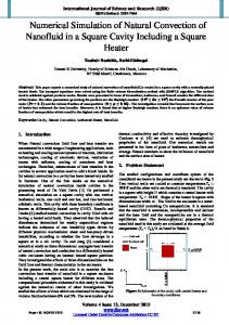
FIG. 1. Schematic diagram showing the known vortical structures of the jet in cross-flow.
right wake vortices from the cross-flow channel floor and their entrainment into the jet core; and (iv) the important topologically invariant flow features. An extensive investigation about the detailed flow evolution process from the developed topological critical points, and their connection to the rest of the flow, is intended to be presented here. II. DESCRIPTION OF THE PHYSICAL PROBLEM
Direct numerical simulations are conducted to investigate the vortical flow development around a square jet issuing normally into a cross-flow. The jet begins as a square sectioned pipe flow which issues into the flat plate cross-flow boundary layer through an orifice. The pipe supporting the jet is placed symmetrically (Fig. 1) with respect to the width of the cross-flow channel floor. We consider an orthogonal Cartesian coordinate system where the origin is at the center of the jet orifice, coinciding with the cross-flow channel floor, and x and y axes are directed along the two axes of symmetry of the orifice (Fig. 1), whereas the z axis is taken along the direction of the jet. Fully developed pipe flow profiles (e.g., White [26]) are used both at the jet-inlet and at the inlet section of the cross stream, and a unit length (when normalized by the jet width “d”) of the square-sectioned pipe supporting the jet is considered for the investigation. This allows the jet boundary layer to develop fully and naturally before it emerges into the cross-flow. The vertical (along the z direction) and the horizontal (along the y direction) lengths of the cross-flow channel have dimensions 9d and 6d, respectively, and its length upstream of the jet axis (z-axis) was taken as 4.5d. It may be noted that in order to capture the detailed 3D unsteady vortical interaction process associated with such flows (as reported in previous experimental findings), the growth of fully developed boundry layers both on the cross-flow channel floor and inside the jet pipe is quite essential, and the implementation of fully developed flow profiles at the jet and the cross-flow inlets ensures that. Moreover, the downstream channel exit was placed sufficiently far 共19.5d兲 away from the jet orifice. Notably, since
The predictions for three-dimensional unsteady interaction of a square jet with an oncoming cross-flow were obtained by numerically solving the following nondimensional 3D incompressible equations of continuity and momentum, D ⬅ ⵜគ · uគ = 0, uគ t + uគ · ⵜគ uគ = − ⵜគ p +
1 2 ⵜ uគ . Re
共1兲 共2兲
In the above nondimensional equations in primitive variables, uគ represents the velocity vector and p is the dynamic pressure. Here all lengths have been nondimensionalized with respect to the width d of the square jet. The velocities are normalized with respect to the average incoming velocity U at the cross-flow channel inlet, and the pressure is nondimensionalized with respect to U2. The Reynolds number is defined as Re= Ud / , where is the kinematic viscosity and ⵜគ is the spatial gradient operator. Boundary conditions
The nonslip wall boundary conditions, u = v = w = 0, are used in the present study. The requirement that there can be no tangential velocity component is responsible for the generation of vortices at the wall and the development of the viscous wall boundary layer. A zero gradient outflow condition was implemented at the downstream end of the cross-flow channel, and the exit was placed sufficiently far 共24d兲 away from the cross-flow inlet. At the exit we use, therefore,
u v w = = = 0. x x x At the inlet section of the jet we use the following fully developed axial inlet velocity profile (White [26]) uគ inlet = 关0 , 0 , w共x , y兲兴:
066302-3
w共x,y兲 =
48 共x,y兲, ␣3 ⬁
tanh 共兲 192d ␣=1− 5 , i5 i=1,3,5,. . .
兺
PHYSICAL REVIEW E 69, 066302 (2004)
SAU et al. ⬁
共x,y兲 =
兺 共− 1兲共i−1兲/2 i=1,3,5. . .
冉
1−
冊
cosh 关共2y − 1兲兴 cos 共2x兲 , cosh 共兲 i3
u
A similar fully developed axial flow profile uគ inlet = (u共y , z兲 , 0 , 0) was used (see White [26], p. 120) at the inlet section of the cross-flow channel. The implementation of such fully developed inlet profiles allowed us to shorten the inlet channel lengths without affecting the natural growth of the boundary layers both on the cross-flow channel floor upstream of the jet orifice and along the jet boundary. The other velocity components at the inlets are set to zero, so that any possible swirling at the inlets is ignored. IV. NUMERICAL METHODS
We employ a finite volume-based method to discretize and solve the set of Eqs. (1) and (2) in primitive variables, together with the boundary conditions specified above, on a high resolution uniform staggered grid system, which prevents the occurrence of pressure oscillation in the configuration. The numerical method employed here is an improved version of the marker-and-cell (MAC) finite difference method of Harlow and Welch [27]. In the interior of the computational domain, the convective terms in the momentum equations are discretized by using a third order accurate upwind scheme, and the viscous terms are discretized using a fourth order accurate central difference scheme. For example, for i 艌 3 the spatial derivatives in convective and viscous terms are approximated as below. For ui,j,k 艌 0, we use ui−2,j,k − 6ui−1,j,k + 3ui,j,k + 2ui+1,j,k u = ui,j,k , x 6␦x
for ui,j,k ⬍ 0 we use u
ui+1,j,k − ui−1,j,k u = ui,j,k , x 2␦x
for ui,j,k ⬍ 0 we use
i 共i兲 = . 2d
u
u
ui+2,j,k − 6ui+1,j,k + 3ui,j,k + 2ui−1,j,k u = − ui,j,k , x 6␦x
and a second order derivative in the diffusion term was approximated by
2u − ui−2,j,k + 16ui−1,j,k − 30ui,j,k + 16ui+1,j,k − ui+2,j,k = . x2 12共␦x兲2 The above numerical scheme is observed to produce time accurate results that are quite consistent with the existing experimental findings of Fric and Roshko [9] and Kelso et al.. [10] for a round jet, and a smooth flow transition was observed at the outflow boundary. In the neighborhood of the wall boundaries, where the flow is directed away from the wall for the discretization of the first order derivative in the convection terms, the third order upwind method was replaced by the second order central difference method instead of using the first order upwind method. For example, for i = 2 (i = 1 being the solid wall) we use second order accurate central difference schemes, i.e., for ui,j,k 艌 0 we use
ui−1,j,k − ui+1,j,k u = − ui,j,k , x 2␦x
and a second order derivative in the diffusion term was approximated by
2u ui−1,j,k − 2ui,j,k + ui+1,j,k = . x2 共␦x兲2 Most terms in the momentum equations were solved by using an explicit computational scheme, but the coupling between the pressure and the velocities was implicit. This semiimplicit formulation was solved using the successive overrelaxation (SOR) method to accelerate convergence. The above-mentioned numerical scheme has been used successfully by several investigators to solve various fluid dynamic problem. For example, among others, recently Peng et al. [28], Sau [29,30], and Chiang et al. [31] have efficiently implemented the scheme and the solution algorithm to study the onset of 3D-flow development through different complex geometries. In order to be sure about the correct choice of the computational scheme, we have run a series of test cases extending over several months with different fourth order and seventh order (e.g., Peng et al. [28]) accurate schemes in as many as seven Pentium IV processors; however, the present method was found to be efficient enough in correctly predicting the associated flow phenomena that are reported in a number of recent experimental findings. The twofold solutions of the velocity field were obtained as follows. First the velocity components are advanced explicitly using the previous state of the flow, having calculated the combined influence of convection, diffusion, and pressure gradients through a time step ␦t. The solution is then advanced in time using a semi-implicit scheme that is formally second-order accurate. The time step ␦t was so chosen that it always satisfies the CFL stability criteria. In the subsequent fold, the adjustment of pressure and velocity is done by an iterative process to ensure mass conservation in each cell. This iterative correction of the velocity field through the implicit continuity equation is equivalent to the solution of Poisson equation of pressure. The process is repeated successively until sum of D values for all the cells became 10−4. Computations are carried out on a system of PENTIUM IV processors. Most runs employed a spatial resolution of 100⫻ 71⫻ 244 grids. In addition to the main production runs, several short simulations were performed to examine the necessity of using different higher order discretization schemes for the convective terms in order to capture the possible presence of experimentally observed flow features known for round jets. It may be noted that each simulation performed here takes about 2500 h of CPU time in the above-mentioned computer system. A grid sensitivity study was performed at various stages of computation to verify the quantitative accuracy of the results presented in the next section and the optimum grid resolution was used. To preserve
066302-4
PHYSICAL REVIEW E 69, 066302 (2004)
THREE-DIMENSIONAL SIMULATION OF SQUARE JETS…
FIG. 2. Streamline pattern on the vertical symmetry plane 共y = 0兲 at t = 6.0. Re= 225, R = 2.5.
the essence of the realistic flow nature, we performed the very extensive and careful flow simulation in the full domain of the physical problem. In order to capture the important flow interaction along the jet/cross-flow interface and the growth of upright vortices from the downstream cross-flow floor shear layer, well resolved fine and uniform grids are particularly used in the computation, which efficiently reproduced the important flow features as experimentally observed by Fric and Roshko [9] and Kelso et al. [10]. In view of the sensitive nature of the flow interaction, the use of uniform grids was preferred to especially avoid any possible interpolation error that could arise out of the non uniformity of the grids. V. RESULTS AND DISCUSSION
In this section we present details of a three-dimensional unsteady flow interaction process around a square jet issuing normal to a cross-flow, as obtained by direct numerical simulations. Figure 2 serves as a representative plot exhibiting the symmetry plane flow characteristics (as induced by the jet/ cross-flow interaction), comprised of the presence of the upstream horseshoe vortex system, the Kelvin-Helmholtz instability-induced shear layer roller formation along the front jet/cross-flow interface, and the growth of unsteady wake vortices at an early stage 共t = 6兲 of the transient flow evolution process. These are reminiscent of previous experimental findings dealing with the interaction of a round jet with an oncoming cross-flow. Besides exploring the detailed flow mechanism, particular emphases have been made to improve our understanding about the physical process of inception and the subsequent growth of the CVP, the process of evolution of the Kelvin-Helmholtz rollers, and the mechanism of growth of the unsteady upright wake vortices from the channel floor boundary layer and their eventual merging with the jet. To avoid any possible confusion, here we may mention that because of some plotting difficulty, the portion of jet streamlines within the vertical pipe in some of the
figures (e.g., Figs. 2–4) was plotted separately and superimposed; however, others are drawn simultaneously. Horseshoe vortex system
The horseshoe vortex, which is usually seen to develop for flow over wall-mounted bluff bodies, is observed to form here (Figs. 2 and 3) and surround [Figs. 4(a) and 4(b)] the lateral jet edges, as the oncoming cross-flow near the channel floor 共z = 0兲 bifurcates laterally upon encountering with the emerging jet. The time-evolving upstream near-wall streamline patterns on the vertical symmetry plane (Figs. 2 and 3), together with the instantaneous streamlines surrounding the jet as presented in Figs. 4(a) and 4(b), reveal the structural evolution of the horseshoe vortex. Here we may mention that the jet orifice on the plane z = 0 covers the area 共−0.5艋 x 艋 0.5兲 ⫻ 共−0.5艋 y 艋 0.5兲. Due to the dominant unsteady nature of eruption of the near-wake vortices from the channel floor and their subsequent entrainment into the mainstream in the form of upright vortices (as it will gradually unfold), and because of spontaneous upward fluid motion from the downstream node (e.g., Figs. 2 and 3), two tails of the horseshoe vortex also experience an unsteady process [Figs. 4(a) and 4(b)] of growth during their downstream extension and while being entrained into the main stream. For example, sometimes [e.g., Fig. 4(a)] both the tails of the horseshoe vortex are seen to get lifted away from the channel floor and join the mainstream, and sometimes one tail gets lifted upward, whereas the other tail remained extended somewhat horizontally. As the presentation of the work progresses, further insight into the physical process of evolution of the horseshoe system may be obtained. Moreover, upon analyzing the data obtained from different higher orders (fourth and seventh orders), accurate schemes, and with much refined grids, we observed that the overall upstream structure of the horseshoe vortex (Figs. 2–4), for the presently investigated range of flow parameters, remained unchanged and it contained only one vortex loop.
066302-5
PHYSICAL REVIEW E 69, 066302 (2004)
SAU et al.
FIG. 3. Flow evolution pattern on the vertical symmetry plane 共y = 0兲 at t = 9.0. Re= 225, R = 2.5.
B. The jet shear layer instability
Notably, Figs. 2 and 3 indicate the process of growth of the shear layer rollers along the upstream jet interface, which are formed due to the Kelvin-Helmholtz-like instability of the jet/cross-flow mixing layer. Upon interacting with the oncoming cross-flow the jet is observed to quickly bend along the downstream direction just after exiting from the orifice. The sequential symmetry plane growth of such vortical rollers along the front side of the jet is also evident from the contours of y vortices as presented in Fig. 5(a), and they clearly demonstrate the unstable phase of the jet shear layer, as resulted due to the impact of the jet with the oncoming cross-flow. A more complete three-dimensional view revealing such a Kelvin-Helmholtz instability-induced roller formation has been presented in Fig. 5(b). The formation of such rollers, along the front jet interface, probably indicates their quasi-steady nature of growth in the region. However, as will be shown later, along the downstream side of the jet these instability-induced rollers exhibit their dominant unsteady characteristic. As far as the three-dimensional structural evolution details of such rollers are concerned, it has been observed (e.g., Fig. 7) that the Kelvin-Helmholtz rollers do not form closed circumferential vortex rings. In fact their open tails upon being entrained upward along the jet lee side eventually join the CVP. For the sake of completeness, in Fig. 6 we present the process of growth of the KelvinHelmholtz vortices for the velocity ratio R = 3.5 and Re = 225. Notably, with the increase in the velocity ratio, the Kelvin-Helmholtz vortices are seen to gain strength and even their numbers are also seen to increase. It may be noted that the growth of such Kelvin-Helmholtz vortices along the initial portion of a round jet has been experimentally predicted by Fric and Roshko [9] and Kelso et al. [10]. It appears that the over all basic mechanism and the nature of formation of such rollers remain similar, both for the round jet as well as for the presently investigated square jet. However, owing to initial curvature variation of
these jets at their entry, it is possible that there will be some quantitative difference in the local flow properties, such as relative differences in the strength and in the extent of spanwise shifting of the Kelvin-Helmholtz and the horseshoe vortex tails away from the jet. Notably for single jets, it has been observed that (e.g., Sau [29,30]) the azimuthal perturbation of a jet is basically controlled by the streamwise dynamics of the developed vortices. To be explicit, an asymmetric (rectangular or elliptic) jet, in absence of a cross-flow and upon entering into an expanded zone, suffers a sequence of azimuthal perturbation. During streamwise evolution, depending on the outflow or inflow type nature of the dynamics of the dominant streamwise vortices, one side of the jet gradually expands outward along a plane of symmetry while getting compressed on the other symmetry plane. As a consequence the initial upstream structure of the jet gets deformed in such a way that, at a downstream location the local jet structure switches its axes of orientation. Whereas a square jet is known to produce a 45° axis switching (e.g., Sau [29]). On the other hand, as it will gradually unfold, the governing flow physics for two mutually interacting jets is far more complex, but interesting. In order to explore the physical process of growth of the Kelvin-Helmholtz vortices as they approach the downstream side of the jet, in Fig. 7 we depict the detailed 3D evolution process of a Kelvin-Helmholtz roller. The streamlines in Fig. 7 are so chosen that they constitute a single roller. Such a figure definitely reveals the fact that the Kelvin-Helmholtz instability-induced rollers do not form closed vortex rings. In fact the open tails of such rollers, while approaching the downstream side of the jet, are continuously being entrained upward along the lee side. Moreover, the presence of a sequence of Kelvin-Helmholtz vortices along the front side of the jet and the absence of similar vortex loops at the lee side, as revealed by the y vorticity contours in Fig. 5(a), also justify the fact that the Kelvin-Helmholtz rollers do not form closed loops or rings. Notably, a similar 3D structural growth (e.g., Fig. 7) of the Kelvin-Helmholtz vortices were observed
066302-6
PHYSICAL REVIEW E 69, 066302 (2004)
THREE-DIMENSIONAL SIMULATION OF SQUARE JETS…
FIG. 4. (a) Instantaneous streamlines showing spatial evolution of the horseshoe vortex at t = 9.0. Re= 225, R = 2.5. (b) Instantaneous streamlines showing spatial evolution of the horseshoe vortex at t = 21.0. Re= 225, R = 2.5.
to take place at every instant of time, and the downstream extended tails of the Kelvin-Helmholtz rollers eventually joined the locally evolving CVP. C. Origin of the counter-rotating vortex pair
While the mechanism of formation of the CVP has been addressed in several recent experiments and simulations (e.g., Refs. [10,16–18,25,32]), the issue of the exact source of its inception remained debatable. To be specific, experimental findings of Kelso et al. [10] and their interpretations (in their Fig. 9) suggest that the shear instability-induced Kelvin-Helmholtz vortices (which form along the front and the lateral sides of the jet) while extending downstream, reorient themselves suitably to form the CVP. Cortelezzi and
Karagozian [25] also predict a similar roll-up and the folding processes of the jet shear layer, leading to the inception of the CVP. On the other hand, the recent numerical findings of Yuan et al. [16] suggest that the inception of the CVP takes place due to the twisting and folding of the jet shear layers that develop on the lateral side walls of the pipe supporting the jet, and not due to reorientation of the Kelvin-Helmholtz rollers. In view of these existing differences regarding the origin of inception of the CVP, in the present study we opted to investigate the issue in greater detail. At a glance, here (Fig. 8) we quickly present the topological arrangement of the developed shear layer critical points on the channel floor, including several foci, saddles; and nodes. Later we shall address how flow evolution from these topologically important critical points remains inseparably associated with the
066302-7
PHYSICAL REVIEW E 69, 066302 (2004)
SAU et al.
FIG. 5. (a) Contours of y vortices indicating the growth of Kelvin-Helmholtz rollers on the vertical symmetry plane 共y = 0兲 at t = 21. Re = 225, R = 2.5. (b) Development of KelvinHelmholtz rollers at t = 21, along the front jet interface as revealed by contours of y vortices. Re= 225, R = 2.5.
organized development of the downstream wake, and how the upward lifted vortices from various spiraling foci (Fig. 8) continue to support the streamwise growth of the CVP. To begin with, in Figs. 9(a) and 9(b) we plot the instantaneous streamlines with several different generic origins, broadly capturing the important physical aspects of the nearfield flow behavior. Notably, the blue streamlines in Fig. 9(a) constitute a Kelvin-Helmholtz roller on the front jet interface for R = 2.5 and t = 21. The red streamlines constitute the horseshoe vortex surrounding the jet orifice, and the black streamlines issue from the two lateral edges of the jet pipe. Firstly, Fig. 9(a) clearly reveals that the black streamlines, together with the blue streamlines, take the active role in the structural development of a pair of counter-rotating vortices,
the CVP. Secondly, the streamwise extended blue streamlines constituting the two tails of the Kelvin-Helmholtz roller, as depicted in Fig. 9(a), virtually surround all the shear layer fluid emanating from the two lateral sides of the jet pipe. On the other hand, the evolution of the red streamlines (constituting the horseshoe system) reveals that the horseshoe vortex tails initially turn around the jet orifice (while maintaining significant distance from the jet), and eventually during their far downstream extension they are entrained into the main stream in an asymmetric way. The local flow unsteadiness in the wake, together with the dominance of transverse pressure gradient in the region, contributes to the unsteady and asymmetric ways of lifting of the horseshoe vortex tails. Furthermore, the spontaneous upward fluid motion from the
066302-8
PHYSICAL REVIEW E 69, 066302 (2004)
THREE-DIMENSIONAL SIMULATION OF SQUARE JETS…
FIG. 6. Development of Kelvin-Helmholtz rollers for the velocity ratio R = 3.5 as revealed by contours of y vortices. t = 9, Re = 225.
nodes, situated immediately behind the jet (e.g., Figs. 2 and 3), forces the horseshoe vortex tails to leave the channel floor. Notably, Fig. 9(a) makes it quite clear that the vortices originating from the horseshoe system cannot be the source of inception of the CVP. Therefore, the inception of the CVP either takes place within the lateral jet-pipe shear layer or through rotation of the tails of the Kelvin-Helmholtz rollers. For further clarity, Fig. 9(b) presents a similar near-field flow evolution pattern for R = 3.5 and t = 9, where streamlines with green and the blue constitute two different Kelvin-Helmholtz rollers. Notably, the evolutional details of the streamlines in Fig. 9(b) display a very similar flow physics, as revealed by Fig. 9(a). The important additional information that may be obtained from Fig. 9(b) is that the process of joining of two different Kelvin-Helmholtz rollers at the back side of the jet remains very much consistent with the mechanism recently proposed by Lim et al. [11]. In order to further analyze the basic process of inception of the CVP, in Fig. 9(c) we plot their (CVP) vorticity corelines in the neighborhood of the jet orifice, together with streamlines originating from the vicinity of their bases. The corelines of the upright vortices which originate from the floor critical points F1 and F2 (e.g., Fig. 8) have also been plotted in Fig. 9(c). At this point we may mention that, throughout the unsteady flow evolution process CVP corelines are observed to emanate from the central part of the skewed lateral jet wall shear layers. Moreover, their inception [as represented by the corelines in Figs. 9(c) and 9(d)] is always observed to take place slightly below the jet orifice
FIG. 7. Three-dimensional evolution of streamlines participating in the formation of a Kelvin-Helmholtz vortex at t = 21.0. Re= 225, R = 2.5.
(on the entry plane). This means that the cross-flow, upon encountering the jet, not only deflects the lateral jet shear layer azimuthally upon emergence, but up to a certain extent also influences the jet shear layers within the supporting pipe to become skewed. During the process, the inception of the CVP takes place within the skewed vortical lateral jet shear layers. Moreover, the streamlines issuing from the bases of the CVP corelines [Fig. 9(c)] possess vortices of opposite sign and their sense of orientation remained the same as the locally evolving CVP [Fig. 9(a)]. However, the extended tails of the Kelvin-Helmholtz rollers, as may be noted from Figs. 9(a) and 9(b), closely support the subsequent downstream CVP evolution process. For further clarity, in Fig. 9(d) we depict the simulated corelines of various vortices, at a different time t = 14, that develop due to jet-cross-flow interaction. Notably, the CVP corelines CL1 and CR1 , as depicted in Fig. 9(d), demonstrate the evolution of the left and the right loop of the CVP in the neighborhood of the orifice, and clearly reveal their growth within the lateral jet shear layers. The parts of the simulated corelines as represented by 共CL2 , CR2 兲 and 共CL3 , CR3 兲 reveal the CVP evolution path beyond the points where upright vortices originating from (F1, F2) and (F3, F4) [e.g., see Fig. 8] meet the CVP. The corelines of various wall vortices
066302-9
PHYSICAL REVIEW E 69, 066302 (2004)
SAU et al.
FIG. 8. Topological arrangement of the shear layer critical points close to the channel floor 共z = 0.1兲 at t = 9.0. Re= 225, R = 2.5.
共WL1 , WR1 , WL2 , WR2 兲 are also depicted in Fig. 9(d), and we shall discuss their development process later in the text. At this point readers may note that for a round jet the inception process of the CVP from the quasisteady vortices, which form within the skewed mixing layers of the lateral jet-pipe walls, was earlier predicted by Yuan et al. [16], and interestingly the present investigation dealing with a square jet also reveals a very similar process of inception of the CVP. Here we may mention that due to some inherent drawback of the software (FIELDVIEW) used for plotting the vorticity corelines [e.g., Figs. 9(c)], they often appeared as broken lines, which are in fact continuous. In view of recent experimental findings on the near-field evolution characteristics of elliptic jets in cross-flow, as reported by New et al. [33], it is important that here we review the governing flow physics for the presently investigated square jet more closely and address the issues concerning similarity between the two flows. Firstly, it is important to note that the physical process of growth of the CVP and the mechanism of entrainment of the Kelvin-Helmholtz vortices into the CVP core (along the jet lee-side) remained very much similar for the circular [e.g., Fig. 3(a) in Lim et al. [11]], the elliptic (Figs. 4 and 5 in New et al. [33]), and the presently simulated [e.g., Figs. 9(a) and 9(b)] square jets. In addition, it may be carefully noted that the simulated flow details, as presented in Figs. 5(a), 5(b), and 6, reveal in the laminar range of Reynolds number (e.g., Re= 225) the Kelvin-Helmholtz vortices, which formed along the front side of the jet, maintained a quasi-steady-state while always remaining attached to it, and there appears no frontal vortex shedding. As a result, the CVP over the orifice, as evident from Fig. 10, is seen to grow with a visibly single deck structure during the course of flow evolution. Here we may mention that the evolving streamwise vortices for the flow, on the corresponding planes, were also found to maintain a single deck appearance. Notably, the simulated kidney (mushroom) shaped CVP in Fig. 10, evolving from the folded lateral jet shear layers, basically corresponds to the middle layer “primary CVP” as classified by New et al. [33] in their Fig. 8. Whereas the growth of the “secondary CVP” (as New et al. [33] clearly mention) is a special feature of the low aspect-ratio elliptic jets, and they are not observed to
form with circular or square jets (e.g., see Refs. [11,32]). Furthermore, since the experiments in Refs. [32,33] are conducted well within the turbulent range of the Reynolds number, the related governing flow physics needs to be analyzed more carefully. Notably, as far as the reason behind the presence of the “primary unsteady kidney vortices” (upper deck), as reported in the above-mentioned experiments [e.g., Figs. 8(a) in Ref. [32] and Fig. 8 in Ref. [33]] is concerned, they are obtained by capturing the periodically shedded leading edge vortices (e.g., Figs. 3 and 4 in Ref. [33]), at a much higher Reynolds number (see also Ref. [32]). To be specific, Haven and Kurosaka [32] in their Fig. 8(a) present both single and the double deck structures of the CVP; in one case they capture the periodically shedded leading edge vortex in their LIF image, and in the other case they do not. Since the formation of the upper deck CVP remained intrinsically associated with the phenomenon of frontal vortex shedding, and since there observed to take place no such vortex shedding for the presently investigated laminar flow, the physical process, therefore, justifies why the CVP should maintain the single deck structure (Fig. 10) here. Further investigation on the physical flow evolution process at a much higher Reynolds number is in progress, and we intend to address such issues in greater detail in one of our future works. D. Unsteadiness and asymmetry of the wake structure
Within the framework of the present paper it is a rather difficult task to address such issues in greater detail. However, we would prefer to extract some useful information mostly from the figures that we have already presented. Firstly, as we have already noted [in Figs. 4(a), 4(b), 9(a), and 9(b)], the horseshoe vortex tails behind the jet exhibit unsteady processes of evolution, particularly during leaving the channel floor and while being entrained into the main stream. Such a flow development is basically initiated and controlled by the unsteady nature of eruption of the downstream channel floor shear layer and their subsequent entrainment into the jet core in the form of upright vortices. It is also important to note that the flow evolution (Figs. 2 and 3) behind the jet, particularly on the vertical symmetry plane 共y = 0兲, takes place basically through two clearly defined
066302-10
PHYSICAL REVIEW E 69, 066302 (2004)
THREE-DIMENSIONAL SIMULATION OF SQUARE JETS…
FIG. 9. (Color) 3D evolutional details of the instantaneous streamlines: (i) constituting a Kelvin-Helmholtz roller (in blue color), (ii) constituting the horseshoe vortex system (in red), and (iii) those (in black) passing through the lateral edges of the jet orifice. t = 21, R = 2.5, Re= 225. (b) (Color) 3D evolutional details of the instantaneous streamlines: (i) constituting two Kelvin-Helmholtz roller (in blue and green), (ii) constituting the horseshoe vortex system (in red), and (iii) those (in black) passing through the lateral edges of the jet orifice. t = 9, R = 3.5, Re= 225. (c) Vorticity corelines of the CVP in the neighborhood of the jet orifice and the evolution of streamlines issuing from the bases of CVP corelines are shown here. The upright vortex corelines issuing from the foci F1 and F2 (e.g., Fig. 8) are also plotted at t = 21.0. Re= 225, R = 2.5. (d) A three-dimensional view of the simulated corelines of various vortices in the near-field of the jet. Here H 共CL1 , CR1 , CL2 , CR2 , CL3 , CR3 兲, 共WL1 , WR1 , WL2 , WR2 兲, and (F1, F2, F3, F4) denote the horseshoe vortex coreline, CVP corelines, wall-vortex corelines, and the upright vortex corelines, respectively, at t = 14, Re= 225, R = 2.5
near-wall nodes. The fluid emanating from these nodes, owing to the existing adverse pressure gradient (as it will be shown later), virtually forces the oncoming vortical shear layer to leave the channel floor and join the jet in the form of upright vortices. Notably, the interaction process between the
upward lifted shear layer and the jet, during the course of flow evolution, was noted to initiate a nearly periodic growth of ringlike vortical structures along the jet lee side. To be more precise, an initial pair of symmetry plane ring formation along the jet lee side (which looked quite similar to the
066302-11
PHYSICAL REVIEW E 69, 066302 (2004)
SAU et al.
FIG. 9. (Continued).
lower pair, at t = 6, as appeared in Fig. 2) was observed at t = 0.59. A very similar flow evolution pattern along the jet lee side comprising a pair of ringlike eddies was noted to take place again at t = 3.51. The structural flow development through nearly similar phases (as revealed by Fig. 2) were observed to repeat during the entire course of flow evolution. While in the intermediate stages the flow evolution pattern along the jet lee side showed several intermittent behaviors, such as the total absence of ringlike eddies (e.g., Fig. 3), the repeated appearance of the mushroomlike eddies in a pair form (e.g., Fig. 11), or the presence of isolated single ring eddies (e.g., Fig. 12). These observations suggest that possibly the flow on the vertical symmetry plane evolves in a nearly periodic fashion with some modulated period. As far as the asymmetry is concerned, at a glance, the near-wall
flow topology (e.g., Fig. 8) seems to imply that the downstream flow evolves through symmetry breaking pitchfork bifurcations. Furthermore, in view of repeated evolution of the symmetry plane flow through nearly equal phases, it remains to be verified if the associated flow transition takes place through a Hopf bifurcation with some (unknown) modulated period. At this point it is worth mentioning that in a recent experimental study Rivero et al. [17] also reported a nearly periodic wake evolution process behind a circular jet issuing into a cross-flow. However, they mention that the jet wake exhibits somewhat less periodic behavior than what one usually observes behind a circular cylinder. Interestingly, the round jet experiments of Kelso et al. [10] also reveal a similar (as in Figs. 2, 3, 11, and 12) symmetry plane wake de-
066302-12
PHYSICAL REVIEW E 69, 066302 (2004)
THREE-DIMENSIONAL SIMULATION OF SQUARE JETS…
FIG. 9. (Contiuned).
velopment (in their Figs. 16, 17, and 22), through the formation of a node (just behind the jet orifice) situated slightly above the channel floor. Along the jet lee side, the evolving flow was noted to contain single or multiple ringlike eddies, and sometime it evolved without such structures.
In order to better understand the symmetry plane flow development, in Fig. 13 we plot the pressure distribution over the entire y = 0 plane. Notably, as expected, along the upstream part of the jet we observe the formation of local pressure maxima, suggesting the local stagnation influence.
066302-13
PHYSICAL REVIEW E 69, 066302 (2004)
SAU et al.
FIG. 10. Vector plots of 共v , w兲 velocities on various x planes through the orifice, indicating the growth of CVP at Re= 225 and R = 2.5.
As we move further upward along the jet/cross-flow interface, the growth of alternative high and low pressure areas in the region seems to reveal the oscillating character of the jet. Notably, Figs. 12 and 13 when viewed simultaneously, they reveal the fact that the area which covers the entire jet region on the symmetry plane and the adjoining places along the jet lee side have much lower pressure. The formation of the isolated localized high pressure region behind the jet orifice near x = 1.2 and situated slightly above the channel floor understandably reveals the presence of a node there. From this high pressure (node) region fluid is expected to move all the way towards the low-pressure jet region. The symmetry
plane streamline plots as revealed by Figs. 11 and 12, and even Figs. 2 and 3, clearly demonstrate such a flow evolution behavior. At a further downstream location (for x 艌 3.7) the formation of another high pressure region coincides with the development of the second node in the area. Interestingly, the existence of a relative high pressure region on the channel floor near x = 2.7 corresponds to the base of the line on which the near-wall downstream moving fluid from the first node and the upstream moving fluid from the second node meet and subsequently leave the channel floor vertically upward to meet the jet (Fig. 12). To this extent, the pressure variation across the channel section can effectively explain the near-
066302-14
PHYSICAL REVIEW E 69, 066302 (2004)
THREE-DIMENSIONAL SIMULATION OF SQUARE JETS…
FIG. 11. Sectional view of the flow development on the vertical symmetry plane 共y = 0兲 at t = 13.65. Re= 225, R = 2.5.
field flow development. Herewith, it is important to note that due to the unsteady character of the wake flow, not only the location of the nodes (e.g., Figs. 11 and 12) on y = 0 continued to vary with time, but the entire near-wall topological structure of the flow, as is evident from Figs. 8 and 14, continued to oscillate with time. To gain further insight into the process of the unsteady and asymmetric nature of the flow evolution, in Fig. 15 we demonstrate the temporal growth of the w velocity profiles over a section of the cross-flow channel. Since within 0 艋 x 艋 5 the jet velocity 共w兲 dominates over the cross-flow 共u兲 velocity (e.g., Fig. 12), the profiles at x = 1, i.e., close to the jet orifice, are seen to exhibit their normal distribution-type growth with respect to the channel span. However, the maximum value of the profiles is seen to shift slightly towards the left. Notably, with streamwise distance the asymmetric growth of the profiles became more significant, and the po-
sition of occurrence of their maximum value was also seen to shift from one side of the symmetry 共y = 0兲 plane to the other with time. Here it may be important to note that at x = 1, 3, and 4 the pick values of the w profiles remained higher at t = 19 than those at t = 22; however, at x = 2 we observe the respective profiles to behave in the opposite fashion. Even the profile behavior at t = 20 and t = 21 demonstrates the truly unsteady nature of growth of the developed flow. E. Entrainment and mixing with transverse jet
As far as the entrainment of the floor shear layer fluid into the main stream is concerned, once again Figs. 4(a), 4(b), 9(a), and 9(b) display unique features, depicting how the upstream vortical shear layer fluid associated with the horseshoe system are continuously being lifted up from the channel floor and subsequently entrained into the main stream as
FIG. 12. Flow evolution pattern on the vertical symmetry plane 共y = 0兲 at t = 22.0. Re= 225, R = 2.5.
066302-15
PHYSICAL REVIEW E 69, 066302 (2004)
SAU et al.
FIG. 13. Iso-contours of the dynamic pressure 共p兲 on the vertical symmetry plane 共y = 0兲 at t = 22.0. Re= 225, R = 2.5.
their tails approach downstream of the jet orifice. Moreover, it is important to note from the symmetry plane (Figs. 2, 3, 11, and 12) wake development behind the jet, particularly within 0.5艋 x 艋 4.0, the major mass entrainment into the jet core takes place from the cross-flow boundary layer, and the existing pressure difference (Fig. 13) in the region collectively facilitate such an entrainment process. A clearer threedimensional process revealing the detailed entrainment process at Re= 225 is depicted in Figs. 16 and 17. Since the near-wall flow evolution process at t = 9, as depicted in Fig. 8, continued through the formation of several topological critical points on the channel floor, it was possible to trace them from a two-dimensional analysis and follow the motion of fluid particles emanating directly from the critical points. The critical points (foci) F1, F2, F3, and F4, as evident from Figs. 16 and 17, play the central role in the entrainment process of the floor shear layer into the jet core. To be more specific, they are in fact the footprint of the upright vortices on the channel floor, from where accumulated vortices leave the floor uprightly. Figure 16 displays such a flow behavior at time t = 9. It is, however, interesting to note that much of the upstream shear layer fluid, even those originating outside the horseshoe system (as revealed by the streamlines in red
and blue), upon approaching the critical points F3 and F4 spiral around them and subsequently leave the channel floor to join the main stream. Figure 17 displays the detailed process of entrainment of the shear layer vortices into the jet core through the formation of upright vortices, at time t = 21. This numerically confirms the experimental findings of Fric and Roshko [9], and convincingly demonstrates the important fact that the vortex structures which are observed in the wake region have their origin in the cross-flow wall boundary layer, and not in the jet. At this point it is important to note that in the near-wake region CVP remains the most active [Figs. 9(a) and 9(b)] feature of the flow, and through the inward dynamics of its vortices CVP effectively entrains the downstream vortical floor shear layer fluid into the jet core during the onward passage. To be more precise, from vortex dynamics we know that a pair of counter-rotating vortices (similar to those in the CVP) with equal and opposite strength ⌫ and separated by a distance 2a, will suck the neighboring cross-flow shear layer fluid towards the jet core with a speed about ⌫ / a. Readers may refer to the recent work by Sau [29,30] for further details, where an elaborate and extensive study on the entrainment process, as governed by the dynamics of the dominant streamwise vortex pairs, has been provided.
FIG. 14. Instantaneous streamlines depicting the flow topology near 共z = 0.1兲 the channel floor at t = 22.0. Re= 225, R = 2.5.
066302-16
PHYSICAL REVIEW E 69, 066302 (2004)
THREE-DIMENSIONAL SIMULATION OF SQUARE JETS…
FIG. 15. Spanwise 共y兲 distribution of the vertical 共w兲 velocity profiles at different z stations and at different time. Re= 225, R = 2.5.
F. Surface and sectional flow structure
As far as the topological flow development upstream of the jet and within the jet section is concerned, Fig. 8 (and also Fig. 14) reveals the formation of a node (N1) at the upstream central point 共−0.5, 0兲 of the jet orifice and a saddle (S2) near (0.35,0), which falls inside the jet orifice area. Some of the upstream moving streamlines originating from the mode N1 are either observed to meet at a saddle point S1 on the vertical symmetry plane near 共−1.4, 0兲, or they join the bifurcation lines from both sides, which pass through the saddle (S1). The downstream moving streamlines originating from the node N1 are seen to bifurcate while approaching the saddle point S2. Furthermore, the streamlines issuing out of the node N1 were observed to remain enveloped by the bifurcation lines originating from the upstream saddle S1, and at the rear side of the jet they converge into two slightly asymmetrically placed spiraling foci F1 and F2, formed near x = 0.55. Behind these two foci (Fig. 8) there appears a second node N2 near (0.8,0) on the plane of symmetry y = 0, which may be better viewed from Fig. 3. It shows that the node is actually located about half a jet diameter above the cross-flow wall and acts as a source, pumping out fluid in every direction. The streamline pattern in Fig. 8 also reveals the existence of a second pair of foci (F3 and F4) close to x = 3.3, where some of the deflected streamlines originating outside the horseshoe vortex system are seen to converge. The accumulated floor vortices were observed to directly leave the cross-flow channel floor from these spiraling critical points (foci) in the form of upright wake vortices (e.g., Figs. 16 and 17). Slightly upstream of this second pair of foci the formation of (Fig. 8) three saddles S3, S4, and S5 was observed. Two of them (S3 and S5) remain somewhat symmetrically placed, one lying on each side of the vertical symmetry plane, and the third one (S4) is observed to form on the line of symmetry itself. As we move downstream of the second pair of foci, the formation of three critical points (S6, N3, and S7) was observed near x = 4.7 in the vicinity of the vertical symmetry plane, comprising one node N3 on the symmetry plane 共y = 0兲 itself and two slightly asymmetrically placed saddles S6 and S7, one situated on each side of y
= 0. It is important to note that the simulated flow topology around the square jet, as obtained from the present investigation, is quite consistent with the topological sketch for a round jet as presented by Kelso et al. [10] in their Fig. 24. The only difference that one may observe here is the relative shifting of the two pairs of foci (F1, F2 and F3, F4), with respect to the jet orifice, in the downstream direction. Such a shifting of critical points, as will be shown later, is a result partly due to the higher values of the flow parameters 共R = 6 and Re= 440兲 used in Kelso et al. [10], and partly may be due to the physical shape of the jet orifice. Furthermore, the observed topology of the time-evolving near-wall flow (e.g., Figs. 8 and 14) reveals that, while the position of an individual critical point continues to vary with time, its relative arrangement as a whole remained invariant during the entire course of flow evolution. The flow topology as presented in Fig. 8 also reveals that there exists two main separation lines on the channel floor, one is the line joining F2 and F4 and passing through the saddles S5 and S7, and the other one is the line joining F1 and F3 and passing through the saddles S3 and S6. Such lines of separation are, however, seen to extend far downstream, beyond S7 and S6. Some of the upstream fluid particles upon arriving at S5 move along the channel floor in the form of a wall-vortex either towards F2 or towards F4, from where they leave the surface and join the locally developed upright vortices. Similarly, on the other side of y = 0 (Fig. 8), the upstream fluid particles (originating outside the horseshoe system) upon arriving at S3 continued to move along the channel floor in the form of another wall vortex either towards F1 or towards F3, from where they leave the surface along with the developed upright vortices. In Fig. 9(d) we have depicted the simulated wall vortex corelines 共WL1 , WR1 兲 and 共WL2 , WR2 兲 at t = 14, originating from the saddles which correspond to (S3, S5) and (S6, S7) respectively (as shown in Fig. 8). The reverse arrows with each of the wall-vortex corelines, as depicted in Fig.9(d), reveal the direction of movement of the wall vortices issuing from the respective saddles as they remained stretched along the channel floor. These wall vortices upon arriving at the foci (F1, F2) or (F3, F4) eventually join the locally developed upright vortices
066302-17
PHYSICAL REVIEW E 69, 066302 (2004)
SAU et al.
FIG. 16. (Color) Upright vortex formation from the channel floor shear layer, their lifting from the topological critical points (F1, F2, F3, F4), and the subsequent entrainment process into the jet core, at t = 9. Re= 225, R = 2.5.
FIG. 17. Upright vortex formation from the channel floor shear layer, their lifting from the topological critical points (F1, F2, F3, F4), and the subsequent entrainment process into the jet core, at t = 21. Re= 225, R = 2.5.
and leave the surface. Notably, the topological sketch for a round jet, as experimentally obtained by Kelso et al. [10], also indicates the development of such wall vortices. The existence of such wall vortices has also been observed by Wu et al. [34], but their origin and connection with the rest of the flow remained unknown. In Fig. 18 we present the near-wall flow topology at t = 9 and for R = 3.5. Importantly, a closer look at Figs. 8 and 18 clearly reveals that with the increase in velocity ratio not only the locations of the first pair of foci (F1, F2) moved upstream, but there also appeared significant relative shifting of all the critical points at R = 3.5. Moreover, the quantum of downstream flow asymmetry has also increased with the increase in the velocity ratio (Fig. 18). Notably, the upstream shifting of the second pair of foci relative to the first pair and their loss of symmetry with respect to the vertical symmetry plane 共y = 0兲 is remarkably significant here. Furthermore, the wake structure between the two pairs of foci is seen (Fig. 18) to become more open at R = 3.5. However, as with R = 2.5, the structural distribution of the floor critical points during the course of temporal flow evolution is seen to remain more or less invariant for R = 3.5 also, except for some occasional modulations which are caused due to the unsteady character of the developing wake. Such findings demonstrate the ex-
066302-18
PHYSICAL REVIEW E 69, 066302 (2004)
THREE-DIMENSIONAL SIMULATION OF SQUARE JETS…
FIG. 18. Streamline pattern on z = 0.1, indicating the upstream shifting of near-wall critical points around the jet for R = 3.5. t = 9, Re= 225.
pected similarity in the overall wake evolution pattern between a round jet (as experimentally predicted by Fric and Roshko [9] and Kelso et al. [10]) and the presently simulated square jet, in the presence of a cross-flow. VI. SUMMARY AND CONCLUSIONS
ers, upon being entrained upward along the jet lee side, however, quickly join the already existed CVP. The present simulations also numerically confirm the fact that the downstream moving channel floor shear layer, while approaching a set of well developed floor critical points (foci), spirals around and subsequently leaves the channel floor vertically upward in the form of upright wake vortices. Such a finding appears to be quite consistent with the existing experimental observations for a round jet as made by Fric and Roshko [9]. Moreover, the spontaneous flow evolution from a near-wall symmetry plane 共y = 0兲 node, which formed just behind the jet, is observed to control much of the near-field wake evolution process. It may be important to mention that during temporal flow evolution, the physical process of growth of the topological floor critical points and their relative arrangement, as a whole, was observed to remain invariant (except for some rare temporal modulations) for a range of values of the Reynolds number and the jet to cross-flow velocity ratio, and the entire mechanism remained quite consistent with the similar experimental predictions for a round jet, as made by Kelso et al. [10].
Presently simulated three-dimensional unsteady flow evolution process around a square jet in cross-flow demonstrates the involved near-field interaction of several generically distinct vortical structures comprising an upstream horseshoe vortex system, the Kelvin-Helmholtz instability-induced shear layer rollers, the counter-rotating vortex pair (CVP), and the down-stream upright wake vortices. Notably, the tails of the horseshoe vortex, while being extended downstream, were observed to be entrained upward in an asymmetric and unsteady way, to join the locally evolving CVP. As far as the source of inception of the CVP is concerned, the present simulation clearly establishes the fact that the CVP originates from the skewed shear layers which develop on each lateral side wall of the jet pipe, and such findings remain quite consistent with the predictions recently made by Yuan et al. [16]. During unsteady downstream evolution, CVP, through its inflow type dynamics, continued to entrain the locally developed wake vortices into the jet core. The simulated findings also indicate that the Kelvin-Helmholtz instability induced rollers, which develop in the front mixing layer between the jet and the cross-flow, do not form closed circumferential vortex rings. The extended open tails of such roll-
This research was supported by Institute of Physics, Academia Sinica, Taipei, Taiwan. One of us (A.S.) would like to thank Professor T. P. Chiang and T. Y. Cheng for their help in generating some excellent figures.
[1] C. J. Baker, J. Fluid Mech. 95, 347 (1979). [2] A. W. Thomas, Phys. Fluids 30, 283 (1987). [3] C. V. Seal, C. R. Smith, O. Akin, and D. Rockwell, J. Fluid Mech. 286, 117 (1995). [4] A. Sau, R. R. Hwang, T. W. Sheu, and W. C. Yang, Phys. Rev. E 68, 056303 (2003). [5] J. Andreopoulos, J. Fluid Mech. 157, 163 (1985). [6] A. Krothapalli, L. Lourenco, and J. M. Buchlin, AIAA J. 28,
414 (1990). [7] R. M. Kelso and A. J. Smits, Phys. Fluids 7, 153 (1995). [8] J. S. Shang, D. L. McMaster, N. Scaggs, and M. Buck, AIAA J. 27, 323 (1989). [9] T. F. Fric and A. Roshko, J. Fluid Mech. 279, 1 (1994). [10] R. M. Kelso, T. T. Lim, and A. E. Perry, J. Fluid Mech. 306, 111 (1996). [11] T. T. Lim, T. H. New, and S. C. Luo, Phys. Fluids 13, 770
ACKNOWLEDGMENTS
066302-19
PHYSICAL REVIEW E 69, 066302 (2004)
SAU et al. (2001). [12] A. E. Perry and T. T. Lim, J. Fluid Mech. 88, 451 (1978). [13] J. E. Broadwell and R. E. Breidenthal, J. Fluid Mech. 148, 405 (1984). [14] J. Andreopoulos and W. Rodi, J. Fluid Mech. 138, 93 (1984). [15] R. W. Coehlo and J. C. R. Hunt, J. Fluid Mech. 200, 95 (1989). [16] L. L. Yuan, R. L. Street, and J. H. Ferziger, J. Fluid Mech. 379, 71 (1999). [17] A. Rivero, J. A. Ferre, and F. Giralt, J. Fluid Mech. 444, 117 (2001). [18] R. I. Sykes, W. S. Lewellen, and S. F. Parker, J. Fluid Mech. 168, 393 (1986). [19] M. Rudman, Exp. Therm. Fluid Sci. 12, 134 (1996). [20] R. W. Claus and S. P. Vanka, J. Propul. Power 8, 425 (1992). [21] A. O. Demuren, Int. J. Eng. Sci. 31, 899 (1993). [22] J. E. Martin and E. Meiburg, J. Fluid Mech. 230, 271 (1991). [23] J. E. Martin and E. Meiburg, J. Fluid Mech. 243, 457 (1992).
[24] W. J. A. Dahm, C. Frieler, and G. Tryggvason, J. Fluid Mech. 241, 371 (1992). [25] L. Cortelezzi and A. R. Karagozian, J. Fluid Mech. 446, 347 (2001). [26] F. M. White, Viscous Fluid Flow, 2nd ed. (McGraw-Hill, New York, 1991). [27] F. H. Harlow and J. E. Welch, Phys. Fluids 8, 2182 (1965). [28] Y-F. Peng, Y-H. Shiau, and R. Hwang, Comput. Fluids 32, 337 (2003). [29] A. Sau, Phys. Fluids 11, 3003 (1999). [30] A. Sau, Phys. Fluids 14, 3280 (2002). [31] T. P. Chiang, T. W. Sheu, R. R. Hwang, and A. Sau, Phys. Rev. E 65, 016306 (2002). [32] B. A. Haven and M. Kurosaka, J. Fluid Mech. 352, 27 (1997). [33] T. H. New, T. T. Lim, and S. C. Luo, J. Fluid Mech. 494, 119 (2003). [34] J. W. Wu, A. D. Vakili, and F. M. Yu, AIAA J. 26, 940 (1988).
066302-20