REVIEW OF SCIENTIFIC INSTRUMENTS 77, 10E907 共2006兲
Three view electronically scanned interferometer for plasma electron density measurements on the H-1 heliac David Oliver,a兲 John Howard, Santhosh T. A. Kumar, D. G. Pretty, and B. D. Blackwell Plasma Research Laboratory, Research School of Physical Sciences and Engineering, Australian National University, Canberra, Acton 0200, Australia
共Received 8 May 2006; presented on 9 May 2006; accepted 23 May 2006; published online 27 September 2006兲 We report the development of a three view electronically scanned millimeter-wave interferometer for plasma electron density profile measurement on the H-1 heliac. The system utilizes an electronically tunable backward-wave oscillator whose output is incident on a fixed blazed diffraction grating such that sweeping the source frequency effects a spatial scan of the plasma cross section. Two diagonal views essentially span most of the plasma cross section, while the horizontal arm views the lower half of the plasma. The diffracted beams traverse the plasma in ⬍1 ms with a spatial resolution ⬃20 mm. A study of the density projection dependence on magnetic configuration shows that the presence of low-order rational surfaces in the plasma gives rise to sharp density gradients in the vicinity of the surface. © 2006 American Institute of Physics. 关DOI: 10.1063/1.2218839兴
I. INTRODUCTION
The H-1 heliac1 is a three period flexible heliac of major radius of 1 m and average minor radius of 0.2 m. The flexibility is provided by a helical control winding that allows the generation of a variety of magnetic configurations. By varying the ratio of the current in the helical and central ring conductors 共see Fig. 1兲 it is possible to change the on-axis between 0.6 and 2.0. rotational transform 共¯兲 An electronically scanned millimeter-wave interferometer 共ELSI兲 has been recently installed on the H-1 heliac for plasma electron density measurement.2 The system is an upgrade of the rotating grating scanned multiview interferometer.3 The ELSI utilizes a backward-wave oscillator4 共BWO兲 capable of a rapid 共⬍1 ms兲 electronically controlled wide-band 共180– 280 GHz兲 frequency sweep. Focusing the output upon a fixed, blazed diffraction grating generates a spatial scan of the plasma. The originally reported system has now been upgraded to provide two diagonal views to supplement the existing horizontal plasma view. The three view ELSI has been used to study the dependence of the plasma density profile on the magnetic configuration for ion-cyclotron resonantly heated hydrogenhelium plasmas at 0.5 T.
polarizers to four interferometers, two of which provide diagonal views of the plasma and one horizontal. In the present arrangement, we supply a linear ramp low voltage signal to the BWO power supply to generate an approximately linearly varying output frequency. The wide bandwidth of the high voltage amplifier required for rapidly changing the cathode bias results in a corresponding increase in the source phase noise. For this reason a fourth beam is required for a reference interferometer that monitors this instantaneous source phase noise. In both diagonal and horizontal view interferometers the probe radiation is focused onto a diffraction grating 共incident angle= 60° and groove constant= 0.91 mm兲 to produce a range of diffracted angles ⌬ = 12°. The diffracted beams are
II. THREE VIEW INTERFEROMETER SYSTEM A. Optical design
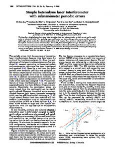
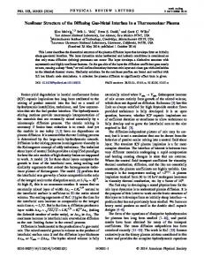
Figure 1 shows a Gaussian ray trace5 of the three view ELSI. The output radiation, which is vertically polarized, is collected and collimated by a periscope consisting of plane and paraboloidal mirrors. The power is split by wire grid a兲
Electronic mail:
[email protected]
0034-6748/2006/77共10兲/10E907/3/$23.00
FIG. 1. A three-dimensional 共3D兲 Gaussian beam ray trace model of the three view ELSI on H-1. The swept frequency radiation is divided into three interferometers on the vertical mounts and then is incident upon the diffraction gratings to produce a fan of angles. The beams are collected by parabolic mirrors and directed into the plasma region and returned back along the incident path for detection. A fourth interferometer on the horizontal table is used to monitor instantaneous phase noise.
77, 10E907-1
© 2006 American Institute of Physics
Downloaded 04 Jun 2010 to 150.203.179.49. Redistribution subject to AIP license or copyright; see http://rsi.aip.org/rsi/copyright.jsp
10E907-2
Rev. Sci. Instrum. 77, 10E907 共2006兲
Oliver et al.
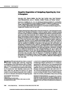
FIG. 2. 共Color online兲 Two representations of the line-averaged densities for a typical 0.5 T minority heated hydrogen discharge in the standard configuration on the H-1 heliac. The upper series shows the successive traces across the plasma as a function of time for the top diagonal, horizontal, and bottom diagonal views. The lower series has the same data as the upper series rearranged into an array representing time 共horizontal axis兲 and spatial position in the plasma 共vertical axis兲 to present a clearer spatiotemporal evolution of the density projection. Slices at fixed spatial position in the lower series have not been shifted by the associated small time delay attending the temporal nature of the sweep.
collected by monolithic parabolic mirrors and injected into the plasma cross section. For the horizontal view, equispaced, parallel beams are directed across the lower half of the plasma volume and then reflected back along the incident path by an internal, segmented plane return mirror. Return optics are mounted on a support structure internal to the vacuum vessel that is contiguous with the main interferometer structure and isolated from vibrations via vacuum bellows. For the diagonal views the collimated beams are focused using secondary parabolic mirrors to produce fans of beams of angular width of 6° that approximately span the plasma poloidal cross section. These fans are returned by internal cylindrical mirrors. In all three views the beams are swept across the plasma from the outside 共220 GHz兲 to the inside 共280 GHz兲 such that phase shift sensitivity is improved in low density regions. For all interferometers, orthogonally polarized radiation from the probe and local oscillator arms are recombined via a polarizer and a paraboloidal mirror onto horn-waveguide coupled broadband zero-biased Schottky diode detectors. Extensive bench tests of the system were undertaken to confirm that the beam propagation throughout the three view
ELSI conformed with Gaussian ray trace modeling. The spot diameter 共1/e power兲 in the plasma region was determined to be 20 mm for the horizontal view and 25 mm for the diagonal views, with a spatial sweep range of ⬃200 mm for all three interferometers. Though effectively equivalent to a 30 chord interferometer, the three view ELSI is a swept three chord system. The result is that the available power per detector is much higher and the optical design somewhat simpler than a standard multichord or expanded beam interferometer. B. Signal analysis
As a result of the frequency sweep, a path length difference between the probe and local oscillator arms gives rise to a small time delay 共and hence frequency difference兲 between the beams combined on the detectors. This is convenient for heterodyne detection, with the resultant intermediate frequency 共IF兲 signal generated in each interferometer being dependent on the path length difference, the range of frequency sweep, and the frequency sweep rate. There are many considerations governing the choice of these parameters.2 For the present configuration, a path length difference of
Downloaded 04 Jun 2010 to 150.203.179.49. Redistribution subject to AIP license or copyright; see http://rsi.aip.org/rsi/copyright.jsp
10E907-3
Rev. Sci. Instrum. 77, 10E907 共2006兲
Three view scanning interferometer
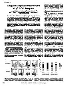
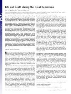
FIG. 3. 共Color online兲 The dependence of the horizontal view density projections 共vertical axis兲 on the rotational transform 共horizontal axis兲. Each projection was taken at 40 ms of a H:He mixed rf heated plasma discharge. The extent of the magnetic islands associated with the 5 / 4 and 4 / 3 loworder rational surfaces is displayed.
⬃3 m, a frequency range of 220– 280 GHz, and a sweep rate of 500 Hz give rise to intermediate frequencies of order ⬃300 kHz which are directly digitized at 3 MHz. Each interferogram is demodulated numerically using the Hilbert transform to calculate the analytic phase of the carrier signal. Multipath and cross talk effects can be removed via an appropriate frequency domain filtering 共different path lengths result in intermediate frequencies separated from the main carrier兲. The instantaneous source phase as monitored by the reference interferometer is subtracted from the phase signals recovered from the probe interferometers, thereby effectively removing common mode phase noise. Finally, the preplasma phase base line is subtracted to reveal the plasma phase shift. III. PLASMA STUDIES A. Three view density profile measurements
The studies reported here focus on minority heated plasmas at 0.5 T that are produced in 0.28:0.17 mixtures of hydrogen and helium by injecting 60– 80 kW at a radio frequency 共rf兲 7 MHz. Figure 2 shows the temporal evolution for the horizontal, top diagonal, and bottom diagonal views for a typical 0.5 T minority heated hydrogen-helium discharge in standard configuration on the H-1 heliac. The demodulated phase shift data are smoothed in a time interval corresponding to the time required for the beam to shift by its diameter. The resulting phase noise level is around ⬃.05 rad compared with peak phase shifts of ⬃3 rad in the horizontal view. Because of the limited number of detectors available at present, these traces were obtained on a shot-toshot basis. As a result, we have not yet attempted to tomographically unfold this data. B. Magnetic configuration studies
The effect of the rotational transform on the plasma confinement and peak density in H-1 has been previously
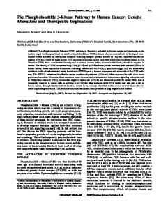
FIG. 4. 共Color online兲 The time evolution of the plasma density projections 1.232 and 共b兲 ¯ for a succession of sweeps for a magnetic axis 共a兲 ¯= = 1.316. The extent of the magnetic islands associated with the 5 / 4 and 4 / 3 low-order rational surfaces is displayed. Each sweep has a period of 2 ms.
reported.6 We have extended this study by utilizing the capabilities of ELSI to observe details of the plasma density projections as a function of the rotational transform 共¯兲. In particular we have noted a strong link between the radial position of the steepest density gradient and the location of low-order rational surfaces ¯= n / m within the plasma volume. The scans in rotational transform were undertaken in increments of ⌬¯= 0.004 in the range of 1.12⬍¯⬍ 1.44. Figure 3 shows the projections of the horizontal view as a function of rotational transform for 1.2⬍¯⬍ 1.35. Also displayed is the vertical location of the low-order ¯= 5 / 4 and ¯= 4 / 3 resonances. The correlation between the location of the rational surface and density gradient is clear. Magnetic mapping and modeling shows that good surfaces exist outside the rational surface in many of the configurations, suggesting that low plasma densities near configurations having deeply embedded rationals may be related more to the efficiency of plasma generation than plasma confinement. Further studies using electron cyclotron heated plasmas are planned to elucidate this. Figure 4 shows the plasma evolution for discharges where the 5 / 4 共¯= 1.232兲 and 4 / 3 共¯= 1.316兲 low-order rational surfaces are present in the outer regions of the plasma. Both cases display a similar gradient increase in the region interior to the location of the rational surface. In both cases it is observed that the density is clamped ⬃3 cm centrally inward of the resonance throughout the plasma evolution. 1
S. M. Hamberger, B. D. Blackwell, L. E. Sharp, and D. B. Shenton, Fusion Technol. 17, 123 共1990兲. 2 J. Howard and D. Oliver, Appl. Opt. 共to be published兲. 3 G. Warr, B. D. Blackwell, J. Wach, and J. Howard, Rev. Sci. Instrum. 72, 2305 共2001兲. 4 ELVA-1, 46 Robezu LV-1004 Riga Latvia 共http://www.elva-1.com兲. 5 G. Warr and J. Howard, Rev. Sci. Instrum. 72, 2305 共2001兲. 6 J. H. Harris et al., Nucl. Fusion 44, 279 共2004兲.
Downloaded 04 Jun 2010 to 150.203.179.49. Redistribution subject to AIP license or copyright; see http://rsi.aip.org/rsi/copyright.jsp