Apr 18, 1994 - out of the body; S is the surface of the element with length dl; D is the diameter of ..... A wave height of H = 5 m and wave period T = 7 set are.
Ocean Engng, Vol. 22, No. 4, pp. 367-385.1995 Copyright Q 1995 Elsevier Science Ltd Printed in Great Britain. All r@tts reserved oo29-8018/95 s9.50 + .oo
00294018(94)00013-1
TIME-DOMAIN SIMULATION OF LARGE-AMPLITUDE RESPONSE OF FLOATING PLATFORMS A. S. Chitrapu* and R. C. Ertekint Department of Ocean Engineering, School of Ocean and Earth Science & Technology, University of Hawaii at Manoa, Honolulu, HI 96822, U.S.A. (Received
27 December
1993; in revtied form 18 April 1994)
Abstmc-Two
numerical simulation models to predict large-amplitude motions of floating platforms are presented. The first method is based on the application of the relative-velocity formulation of Morison’s equation for force calculations. The second method developed in this work uses the three-dimensional potential theory in time domain. In this method, both the Froude-Krylov and scattering forces are calculated by considering finite wave amplitude effects in random waves. The effect of various nonlinearities on the low-frequency motions and highfrequency tether-tension response of a tension leg platform are studied using these simulation models in conjunction with power spectral methods. The presence of current and the nonlinear drag force are observed to have a significant effect on the low-frequency motions and tether tensions.
1.
INTRODUCTION
Response of floating platforms is very much influenced by low-frequency drift forces and high-frequency springing forces. The higher-order forces occur due to both potential and viscous effects and are caused by several nonlinear effects in the fluid-body interaction problem. The nonlinearities include the fluid forces, such as the quadratic drag force, system nonlinearities, such as those related to the equations of motion, nonlinear effects of the positioning system and nonlinear effects due to the free-surfaceforce integration. The influence of potential drift and springing forces on the motion response of semisubmersibles and tether tensions of TLPs has been studied by several researchers (Pinkster, 1979; De Boom et al., 1983; Salvesen et al., 1984; Petrauskas and Liu, 1987; Kim and Yue, 1991) however, the influence of viscous forces on the predicted motion response has not been studied in detail. Bums (1983) presented a method to calculate the viscous drift force and the surge response of a TLP in irregular waves. Ertekin and Chitrapu (1988) and Chitrapu et al. (1993) computed viscous drift forces and the resulting response in all six degrees-of-freedom of a TLP in regular and random waves. Chitrapu and Ertekin (1992) presented numerical results showing the importance of viscous drag forces on the high-frequency tether-tension response of a TLP. Numerical simulation of platform motions together with spectral methods were used to obtain the results in that study.
* Presently with Engineers India Ltd, ETD-Analysis, 1 Bhikaijicama Place, New Delhi, India. t Corresponding author. 367
368
A. S. Chitrapu and R. C. Ertekin
Maeda et al. (1992) studied the response of a semisubmersible platform in directional waves. They observed that viscous effects are very important in certain frequency ranges and dominate the steady drift force and low-frequency motions of the platform. Comparisons with experimental results showed good agreement only after the viscous effects were included. A similar observation had been made earlier by Kobayashi er al. (1987) with regard to the surge motions of a TLP. Donley and Spanos (1992) presented a method to study TLP response including the effect of potential and viscous drift forces. In that study, the viscous drag force was calculated up to the mean water level using the statistical quadratization procedure. Most of the previous studies on the simulation of platform motions were based on a method that employs constant hydrodynamic coefficients (Finnigan ef al., 1984) or on the memory-effect integral formulation (Chou et al., 1983, Takarada et al., 1986). In these methods, the equations of motion are formulated assuming “small” platform motions. Also, in some cases, the drag force is linearized or calculated over the mean wetted length of platform members. Paulling (1977) presented a time-domain model for the simulation of nonlinear platform motions. Huang et al. (1982) presented experimental results for forces and motions in regular waves of a semisubmersible having a large permanent list angle. Takarada et al. (1986) studied the large-amplitude motion behavior of a semisubmersible, including capsizing, using nonlinear time-domain simulations and experiments. Soylemez and Incecik (1989) presented a nonlinear time-domain simulation method to predict the large-amplitude motions of a semisubmersible platform. Results presented in that study indicate that integration of forces acting on the complete immersed length of platform members can cause additional steady tilt of the platform. The steady tilt angles predicted by the nonlinear simulations showed partially satisfactory agreement with the experimental data. From this discussion, it appears that several aspects of the large-amplitude nonlinear response of floating platforms cannot be satisfactorily explained by the existing computational procedures. In this study, two numerical motion simulation models are developed to simulate large-amplitude nonlinear motions of platforms. The two models differ in the way the external forces are computed. In both cases, the complete nonlinear rigid body equations of motion are solved in the time domain. In the first method, the force and response time histories are obtained by a time-domain simulation method which uses Morison’s equation for force computations. The second model is based on the combination of potential and viscous effects in the time domain. In this method, hydrodynamic coefficients and wave exciting forces, obtained a priori using the three-dimensional potential theory, are used to determine the forces acting on a platform which makes large motions. The Froude-Krylov forces are obtained by integrating the undisturbed wave-pressure up to the instantaneous surface elevation as done by De Kat and Paulling (1989) who showed that the Froude-Krylov forces are dominant in all wave conditions. They found very good agreement between their experimental data and predictions for the large amplitude ship motions, both in capsizing and non-capsizing conditions. They also pointed out the adequacy of the linear wave-theory applied to large amplitude waves in deep water as demonstrated by Sobey et al. (1987).
369
Time-domainsimulationof floatingplatforms
First-order memory effects are included through the velocity-based convolution integrals. It is to be noted that an alternate method that can be used in determining the memory effects is the state space model, see for example, Jiang and Schellin (1990). The memory effects considered here are largely based on the early works of Cummins (1962), Ogilvie (1964) and Wehausen (1967, 1971) in the application of linear potential theory in the time domain, and on the recent work of De Kat and Paulling (1989). Viscous effects are included through the nonlinear drag term of Morison’s equation. The rigid-body equations of motion of the platform are presented in Section 2. Section 3 deals with the details of computing the forces acting on a platform. Both approaches to force calculations, that is, Mot-&n’s equation and the potential-theory methods, are discussed. Derivation of the equations of motion, suitable for timedomain integration, are presented in Section 4 for both methods of force computation, Numerical results for the case of a TLP are presented and discussed in Section 6. 2.
THE EQUATIONS
OF MOTION
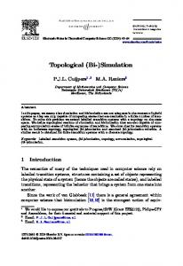
Three different coordinate systems are used for the determination of wave and body kinematics/dynamics (see Fig. 1). The g-system is the inertial system whose origin is tixed at the center of gravity of the platform. The b-system is fixed in the body and translates with respect to the g-system. The w-system is located on the still water level with its x,,,~-axis placed along the direction of wave propagation (Fig. 1 shows the particular case of 0” wave approach). The local (l-system) member system is fixed in each member such that the xi,-axis of the system is along the member axis. Details of the transformations between different coordinate systems are given in Chitrapu (1992) and Chitrapu et al. (1993). The equations of motion expressing the motion of the body are written in terms of the external forces and moments and the mass and inertia properties of the body, using Newton’s and Euler’s equations of motion, are (see, for example, Paulling, 1977):
X
w3 xf1
SWL W
xS3
S
Fig. 1. Coordinate system definition.
370
A. S. Cbitrapu and R. C. Ertekin
$ =[I]-‘{M,
- o x ([I] o)} ,
(1)
$=[B]-1” )
where x,v are the translational displacement and velocity vectors of the origin of the b-system; 8, o are the angular displacement and velocity vectors; F, Mb are the total external forces in the g-system and external moment about the origin of the b-system, respectively; [Ml, [I] are body mass and inertia matrices and [B] is the transformation matrix relating angular velocities to time-derivatives of the Euler angles. Equation (1) represents a system of 12 first-order, coupled, nonlinear ordinary differential equations with x, v, 0 and o being the 12 state variables. It is worthwhile to note the following nonlinearities present in the equations of motion: (i) The coordinate transformation matrices contain terms which are products of trigonometric functions of the rotational displacements (see Chitrapu et al. 1993). (ii) The presence of the o x lo term. (iii) The fluid forces and moments may depend on the wave elevation and particle velocities in a nonlinear manner. As will be discussed in the subsequent sections, the computation of the fluid force over the instantaneous wetted-length of a platform member introduces a nonlinear dependence of the force on the wave surface elevation. Viscous forces, such as the relative velocity drag force, depend on the square of the particle and body velocities. The forces due to the positioning system may also include nonlinear terms containing particle and body kinematic variables. 3.
3.1.
Hydrodynamic
In this approach,
HYDRODYNAMIC
FORCES
AND
MOMENTS
forces using Morison’s equation
the total force on the platform can be written as:
F=Fs+F,+F,+Fv+F,,
(2)
where Fs. is the hydrostatic force, FP is the Froude-Krylov force, F, is the force due to body- and wave-particle accelerations, F, is the relative velocity (viscous drag) force, and Flcl is the force due to the positioning system. Other forces, such as the wind force, can be added to the right-hand side of Equation (2). The force per unit length of a member at any point m on the nth member is given by:
where p is the pressure due to the incident wave; n is the unit normal vector pointing
371
Time-domain simulation of floating platforms
out of the body; S is the surface of the element with length dl; D is the diameter of the member; C,,, and C, are the added mass and drag coefficients, respectively; $!-, an- are the relative velocity and acceleration, respectively, at any point 111normal to the nth member axis and p is the mass density of the fluid. Equation (3) is a modified form of Morison’s equation (Morison et al., 1950). The first term on the right-hand side of this equation is the Froude-Krylov force. The hydrostatic pressure force is also included in this term. The second term is the acceleration force, which is considered proportional to the relative acceleration normal to the member axis, and the last term is the relative velocity drag force. The water particle velocity and accelerations are determined using the Stretching Method (Wheeler, 1969) in regular and random waves to account for finite waveelevation effects. Detailed derivation of the equations to compute various force components and particle kinematics in random waves can be found in Chitrapu (1992). 3.2.
Hydrodynamic forces using the potential theory
In this approach,
the total force acting on the platform is written as:
F=Fs+Fp+FR+FD+Fv+FM,
(4)
where Fu is the radiation force due to body motion, and Fu is the scattering force due to the diffraction of waves by a fixed body. The remaining terms in Equation (4) have the same definitions as those given in Equation (2). We can see from Equations (2) and (4) that the main difference in the computation of forces in the two methods depends on the way the wave excitation and hydrodynamic forces are computed. The method developed here is to combine the three-dimensional potential theory results in the time domain in which the effects of large-angle platform motions are included. It has roots in De Kat and Paulling’s (1989) work, which employed the twodimensional strip theory in the time domain to simulate large-amplitude motions of ships. 3.2.1. Radiation forces. The initial value problem of forced motion of a body has been studied by a number of researchers. Cummins (1962) proposed the method of impulse response function and a decomposition for the velocity potential to represent the forced and arbitrary, but “small”, motions of a ship. Extensive theoretical investigations of this problem were also conducted by Ogilvie (1964) and Wehausen (1967, 1971). In this study, the theory based on Cummins’ decomposition is used to compute the radiation forces. To do this, we write the following expressions for forces (and moments): FRi( t) = - A,.@; -
m Ljk(T)V; (t-7) d7, I0
j,k = 1,2 ,..., 6
,
(5)
where V: and ai are the components of the absolute velocity and accelerations of the center of gravity of the body, Ajk are the constant (genuine) added-mass coefficients and Ljk are the kernel functions. The first term on the right-hand side of Equation (5) is analogous to the added-mass force, and the second term is the memory-effect integral based on the velocity of the body. It may be noted that Equation (5) is applicable to arbitrary motions of the body, including sinusoidal motions.
372
A. S. Chitrapu and R. C. Ertekin
Ogilvie (1964) derived expressions relating the frequency-dependent coefficients to time-domain counterparts. These are written as: Ljk(T) =
A,
1,om Bj,(U) COS
UT
I
= Ajk(a’)
+ $
hydrodynamic
do )
mLjk( 7) sin o’r dr I0
,
where u’ is any arbitrary frequency, Ajk(u’) and Bjk(o) are the frequency-dependent added mass and damping coefficients, u is the wave frequency and T is the time lag. Equations (5) and (6) provide all the necessary information to calculate the radiation force and moment acting on a platform due to arbitrary, but “small”, body motions. These linear radiation forces are to be incorporated into a large-amplitude motion simulation model. De Kat and Paulling (1989) proposed two methods to do this for the problem of ship motions with forward speed. The same approach is used here, with certain modifications due to the differences in coordinate systems. The two methods differ in the way the velocities and accelerations used in Equation (5) are computed. In the first method, it is assumed that the rotational angles are small so that no distinction is made between the rotated position of the body and its equilibrium position. This method is more consistent with the linear theory assumption. The linear and angular velocities (and accelerations) are first determined in the space-fixed (g-) system. Radiation forces and moments are computed in the g-system using Equation (5). The moments (which need to be computed in the b-system) are assumed to be the same as those in the g-system (a consequence of assuming that the body be upright in the g-system). In the second method, the translational velocities and accelerations are first determined in the g-system. These are then resolved in the b-system and then used to calculate the forces and moments in the g-system. The velocities and accelerations are given by:
(7) where [P] is the coordinate transformation matrix, consisting of the Euler angles, for the transformation between the b- and g-systems. The forces and moments are calculated using Equation (5). The moments are then transferred back to the b-system, where the large angles are retained in the process. 3.2.2. Scattering forces. The scattering force in the time domain is computed using the wave exciting forces obtained by solving for the diffraction potential in the frequency domain. Here, it is assumed that scattering potential and force components could be obtained separately from the Froude-Krylov forces in the frequency-domain solution. Modifications similar to those made for radiation forces are made here to obtain the scattering force for a platform making large-amplitude motions.
373
Time-domain simulation of floating platforms
It is assumed that diffraction forces are given in terms of the frequency-domain transfer functions (from linear diffraction theory) as: H?(o)
=
mJ)
A
j=12 , ,...,6 >
,
(8)
where F?(a) is the complex diffraction force at frequency u. The diffraction force in the time-domain can be given as (see De Kat and Paulling, 1989): FDj(t)=AHf’(a)eie,
O=kx-utfc,
j=l,...,
6,i=J-1,
(9)
A, k, u and E are the amplitude, wave number, frequency and phase angle of the wave, respectively. Note that Equation (9) is written assuming that the diffraction force is a linear function of the wave amplitude. Also, the phase information is contained in ZZy(u). Equation (9) can be written as:
where
FDi( t) = A { HRj( a)
CO&
-
ZYZj(U) Sinfl} ,
j=
1,2 ,..., 6 ,
(10)
where only the real part of Equation (9) has a physical meaning. HRj(o) and ZZZj(o) are the real and imaginary parts of H?(u). For long-crested random waves, the diffraction force can be obtained in a similar manner, that is, F&t)
= 2
A, { HRj( u,) cos (ks
- UJ + E,) - HZj( u,,) sin (kg
-
UJ
+ E,)}
(11)
n=l
where A,, k,,, un and E, are the amplitude, wave number, frequency and phase angles of the nth wave component, respectively. In Equations (10) and (11) the wave elevation simulated at the center of gravity of the body is considered. The force and moment components given in Equations (10) and (11) are expressed in the g-system. Using similar arguments as given for the radiation forces for large angle motions of a platform, the diffraction moments in the b-system are assumed to be the same as those given by these equations. The moments are transformed to the b-system when Method (2) is used. All the force components are computed over the instantaneous wetted-length of the platform members, as done in Morison’s equation method. Viscous forces are also included using the relative velocity drag term of Morison’s equation. 4.
FORMULATION
OF THE EQUATIONS
OF MOTION IN THE TIME
DOMAIN
The force and moment terms appearing on the right-hand side of Equation (1) depend on the displacement, velocity, and acceleration of the platform. That is, the right-hand side contains not only the unknowns but also their derivatives. This creates numerical difficulties in the integration of the equations. In order to solve this problem, the equations are reformulated wherein the acceleration-dependent terms are moved to the left-hand side of the equations. The general procedure followed here is similar to that described in Paulling (1977) and Paulling and Shin (1985). Because the forces which depend on the body accelerations are computed differently in the two methods discussed in Sections 3.1 and 3.2 [see Equations
374
A. S. Chitrapu and R. C. Ertekin
(2) and (4)], the procedure to formulate These two methods are discussed next. 4.1.
the equations
of motion is also different.
Morison’s equation method
We can write Equation
(3) as:
dF”( t) = dF:( t) - CMa&N dl ,
(12)
where C, = C,p 7~0’14 and the body acceleration term (a&,,) has been separated from the relative acceleration term in Equation (3). All the other terms on the righthand side of Equation (3), except the body acceleration term, are included in dF’:(t) in Equation (12). We can write Equation (12) as: dF”( t) = dF:( t) + dF:( t) .
(13)
The elemental moment about the origin of the b-system can similarly be written as: dM”( t) = dM:( t) + m(t)
,
(14)
where cW:(t) and dM:( t) are the elemental force and moment that depend on the translational and angular accelerations of the body. All the remaining forces and moments are included in the dF”,(t) and dM:(t) terms. The total force and moment (which depend on body accelerations) on the nth member are obtained by integrating dF;(t) and dM:(t) over the instantaneous submerged length of the member, P(t). The total acceleration force and moment on the platform are then obtained by summing the memberwise forces over all members of the platform. They can be written in the following manner:
F,(t) = [al(t)]
$ +[a&)] g
WA0 = [~I(~)1
$ +P&)1 2
(1%
9
(16)
7
where al(t), a*(t) and b,(t), b2(t) are the added mass and moment matrices, respectively. The total force and moment acting on the platform at any time t is then given by: F(t) = F,(t) + F,(t) ,
(17)
M,,(t) = Ma(f) + M,(t) 9 where F,(t) and M,(t) are the quantities resulting from integrating dF:(t) and dM”,(t) along the member length and then summing over all members of the platform (similar to the procedure followed for acceleration dependent forces). F, and M, include all other forces such as body weight, mooring restoration, drag force, etc. Using Equations (15)-( 17), we can write Equation (1) as: dv 5 = [all(QlFO(4
+
[ad41 (WO - 61x 140) 7
!$f=[adOlF,(Q +b~&)l
C&d0-
0
x [Zlo) y
(18)
375
Time-domain simulation of floating platforms
dx -=v, dt
$ =[B]-lo
)
where
b11(01[4~)1 = ([Ml- h(01) -[%(Ql -l [II - [b2(91 1 . 1 [ -PlWl [ b2lWl [a22(91
(19)
The right-side of Equation (18) does not have any terms which depend on accelerations and hence can readily be evaluated at any time. 4.2. Potential-theory approach This approach is similar to the one used for Morison’s equation method discussed in Section 4.1. Some differences occur because of the method in which the radiation forces are computed here. Following the development in the previous section, the total force and moment acting on the platform can be written as [see Equation (17)]: F(t) = FR(f) + F,(t) ,
w
where F,(t) is the radiation force (moment) and F,(t) is the sum of all other forces. Using Equation (5) for the radiation force and moment, we can write the total force and moment as:
F(t) = [all M(t)
= [b,]
$ +[a212 +F,,(t) , $ +[b,] $ +M,,(t)
(21)
.
In Equation (21), dvldt and doldt are the translational and angular accelerations, and together they constitute the components of acceleration a* used in Equation (5). It is also noted that the memory-effect integral terms for j = l-3 [second term in Equation (S)] are now included in F,,(t), along with other force contributions from diffraction, Froude-Krylov, etc. The corresponding terms for j = 4-6 are included in M&J. M, MT PII and P z1 are the 3 X 3 partitions of the 6 X 6 constant addedmass coefficient matrix Aik with the negative sign included [see Equation (5)], that is:
[@,I= [
All
Al2
A13
41
A 22
A23
A31
A32
A33
= ,1[a23
4,5,6, k = 1,2,3
Lb11= [-Ajtcl,
j =
[bl = [-Aj/cl,
j,k = 4,5,6 .
[-Ajk]
,
j = 1,2,3, k = 4,5,6
(22)
It should be noted that the added-mass matrices [al], [u2], [b,] and [b,] are independent of time, as a consequence of the assumptions made in deriving the radiation
376
A. S. Chitrapu and R. C. Ertekin
force and moment in Method (1). On the other hand, if we use Method (2), the velocities and accelerations are given by Equation (7) which makes the added mass matrices time-dependent. The force and moment are now written in the form of Equation (21) as
F(t) = [a,(t)1
$ +[e(t)1 $ +F,(t) ,
M(t) = [h(Ol$ + where the time-dependent
7
(23)
added mass matrices are given by
[6(t)]
= ]-A,,]]P],
bmi
= wjki,
[h(t)]
= [-AjkI[f’I,
[b,(t)] = [-Ajk],
[bdt)l~ +K(t) j,k = 1,2,3 ,
i = 1,2,3 , j = 436,
k = 4,5,6 , k = 1,2,3 ,
(24)
j,k = 4,5,6 .
Thus, the two methods of computing the radiation forces result in the change in added-
mass matrices. The remaining procedure to obtain the equations, similar to Equations (18) and (19), is the same for both methods. In the present study, both Methods (1) and (2) have been implemented in the computer programs developed. Both methods gave very similar results. This is expected, because the numerical model has been applied to a tension-leg platform which has “small” motions. For this reason, further simulations are carried out using Method (1) only. The two methods may yield different results in the case of platforms undergoing larger motions, such as semisubmersibles, because of the different assumptions made in formulating the two methods. The present methods are being applied to semisubmersibles, and the results will be presented in a subsequent article. 5.
APPLICATION
The theory presented in the previous sections is applied to a tension leg platform whose details are given in Teigen (1983) and also in Chitrapu and Ertekin (1992). The half-amplitude Bretschneider wave spectrum given by:
with significant wave height H, = 11.4 m and spectral peak period To = 15 set is used in the irregular-sea analysis. A steady, uniform current of 0.91 m/set is also used in regular and random wave cases. A constant drag coefficient of 1.0 is used for all members and frequencies. It should be noted, however, that one must, in principle, consider the dependency of the pd on the Keulegan-Carpenter number, especially with regard to the particular frequency and low K-C number ranges under consideration. This work is left to future investigation. The linearized hydrodynamic coefficients and exciting forces have been obtained using a computer program based on the Green function method (Wu, 1984). A total
377
Time-domain simulation of floating platforms
of 600 panels (150 panels per quarter) have been determined to be satisfactory because higher-order potential forces are not considered in the present approach. The added mass and damping coefficients obtained in this manner are then used in Equation (6) to obtain the kernel functions and constant added-mass coefficients. The upper limit for the integration in Equation (6), is replaced by a suitable cut-off frequency. A cubic spline interpolation scheme is used to obtain damping coefficients between this cut-off frequency and the frequency at which the damping coefficient becomes zero. Equation (6), is integrated using Filon’s method (see Hildebrand, 1974). The constant added-mass coefficients are computed using Equation (6)2 from the kernel functions obtained from Equation (6),. The added-mass coefficients computed in this manner showed some scatter for different values of frequency, CJ’, used in Equation (6),. Several test computations have been made with different cut-off frequencies for damping coefficients, to determine the kernel functions. The computed A, did not show significant differences. The upper limit of the integration in Equation (5) is replaced by a constant value, r,,, above which the kernel function Lij(7) reaches a constant value. This value has been chosen to be the same for all the kernel functions Lij(T), based on the function which takes the longest time to reach a constant value. To evaluate all memory effect integrals, a value of 30 set is thus selected for T,,, and the trapezoidal algorithm is used. 6.
RESULTS
AND
DISCUSSION
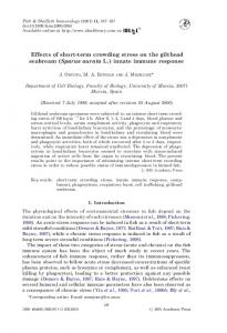
The response of the platform in regular wave groups is studied first. All the results presented in bi-chromatic wave cases are obtained using Morison’s equation. Two regular waves with equal wave heights of HI = HZ = 5 m and wave periods equal to TI = 7 set and T2 = 7.5 set are used. These wave periods are such that their difference frequency corresponds to a period of about 105 set, which is close to the surge natural period of the TLP. Similarly, the sum frequency of these two waves correspond to a period of 3.5 set, close to the natural period in pitch of the TLP (which is 2.5 set). The wave surface elevation generated for the combined waves is shown in Fig. 2.
-101,,,,,,,,,,,,,,,~,,‘,,,,,,,,,,,....,..,, 0
50
100
150
200
250
300
350
Time (s)
Fig. 2. Wave surface elevation (bi-chromatic waves).
400
378
A. S. Chitrapu and R. C. Ertekin
-101.,,.,...,,‘,.,,~,.,,...,,....,.~,,,,,,, 50
0
100
150
200 250 Time (s)
300
350
400
Fig. 3. Time-history of surge response (hi-chromatic waves).
The surge motion obtained from time-domain simulation is shown in Fig. 3. The surge motion shows long period oscillations, with a period corresponding to the difference-frequency of the two waves. Time histories of different force components have been obtained to study their effects on response. The drag force spectrum in the case of the two waves acting without current is shown in Fig. 4. The low-frequency force peak is to be noted in this figure. The tether-tension spectrum is shown in Fig. 5. The second- and third-harmonic responses of tether-tension are significant and appear to be equally important as the response occurring at the wave-frequency. The platform response using the potential theory approach is studied next. These results are evaluated by comparing them with the results obtained from Morison’s equation. This comparison provides a preliminary validation of the potential-theory simulation model developed in this study. Comparisons are made for regular and random wave cases, including current. 3E+012
I
I
-z 2E+012-
ZI Y e 4 g lE+0120 ::
0.00
0.10
0.20 0.30 Frequency (Hz.)
0.40
0.50
Fig. 4. Spectra of surge drag force (hi-chromatic waves).
379
Timedomain simulation of floating platforms
%4E+013 “z .@E+OlJ d
ix+013 I% 1fz+01.3
OE+OOO 0.00
0.10
0.20 0.30 Frequency (Hz.)
0.40
0.50
Fig. 5. Tether-tension spectrum (bi-chromatic waves).
Figure 6 shows the surge motion obtained using the two methods in regular wave and current conditions. A wave height of H = 5 m and wave period T = 7 set are used with a steady current of 0.91 m/set. The result for the pitch motion is shown in Fig. 7. The reason for using a “small” wave period is to validate the simulation model based on Morison’s equation. It appears that this empirical method, used for force calculations, yields reasonably accurate results when compared with the results obtained from the more accurate potential theory method. It is clear that for longer wave periods the diffraction effects will be of lesser importance, and hence, the two methods will yield very similar results (recall that viscous effects are modelled in the same manner in both methods). The method based on the potential-theory appears to give slightly smaller response magnitudes in both motion modes. This may be because the diffraction effects are accurately modelled in the potential theory. Considering the fact that the wave period
10.0 8.0 x
-
Pot. theo Morison’s Y qn.
250
300
6.0
h (jj 4.0
0.0
UUI 0 50
100
150
200
350
400
Time(s)
Fig. 6. Surge response prediction using Morison’s equation and potential theory (H = 5 m, T = 7 set, uniform current).
A. S. Chitrapu and R. C. Ertekin
0.02
-0.05
Fig. 7. Pitch response
!,,,,,““,““,,“,,,,,,,,,,,,,,,,,,,,~ 0 50 100 150 prediction
200 Time(s)
250
300
using Morison’s equation and potential uniform current).
350
4 10
theory (H = 5 m, T = 7 set,
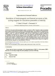
used is in the vicinity of the limiting value for the application of Morison’s equation, it appears that the diffraction effects begin to affect the platform response, and hence, the potential theory method is expected to predict the response more accurately. A similar situation is observed in the case of random-wave response. The surge response obtained by the two methods is plotted in Fig. 8 and pitch motions are compared in Fig. 9. Once again, it is seen that the agreement between the two methods appears to be quite good. It should also be noted that the added-mass values in Morison’s equation method are time-dependent, due to the variable submergence of platform members in time. As mentioned before, the added-mass matrices [see Equations (15) and (16)] are computed at each time step by integrating the elemental acceleration-dependent forces over the complete immersed length of each platform member. However, in the potential-theory method, the constant added-mass coefficients [see Equation (22)] are used in calculating the response. The variation of surge added mass with time in irregular waves, in the case of Morison’s equation, is shown in Fig. 10. The constant surge added-mass value in the case of potential-theory method [calculated using Equation (6),] is 27.38 x lo6 kg. The potential theory appears to predict a higher value as compared to Morison’s equation method which could be another reason for the smaller response predicted by the potential-theory method. From the preceding discussion, it appears that the simulation model based on the application of potential theory in the time domain gives reasonable results. As described in earlier sections, this model can include potential and viscous effects in a largeamplitude platform motion simulation model and, therefore, will be very useful in the study of the extreme dynamic responses of floating platforms. 7.
SUMMARY
AND
CONCLUSIONS
The nonlinear response of floating platforms under different conditions, such as regular, bi-chromatic and random waves, and current, is studied using two time-domain simulation models. The two models differ in the way the external forces are computed. Both models consider several nonlinear effects and the complete nonlinear rigid-body equations of motion are solved in the time domain.
Time-domain simulation of floating platforms
381
8 PI
382
A. S. Chitrapu and R. C. Ertekin
383
Time-domain simulation of floating platforms
2o0I..
. 200 8..
‘.
400 ‘.
.
Tie
.
.
600 ”
“.
800 1.
‘.
.
1000 0..
.
.l 1200
(s)
Fig. 10. Surge added mass using Morison’s equation (random waves).
The platform responses predicted indicate that the presence of current and consideration of nonlinear drag force can have significant effects on the low-frequency motions and springing tether-tension responses of a TLP. The results obtained by the two methods are compared in order to provide a preliminary validation of the potentialtheory model. This model, due to its ability to include potential and viscous effects more accurately in a large-amplitude simulation model, is expected to be very useful in predicting the resonant motions of floating platforms. Two of these cases, namely the low-frequency surge motion and springing tether tension response, are studied here. In this work, the complete nonlinear equations of motion are used. The nonlinearities due to the instantaneous wetted length of platform members are included in all force calculations, including the viscous forces. It is worthwhile, however, to note that there are certain nonlinear components of the forces that could not have been included in here. For example, one can argue that the drift the present method predicts is due to finite wave elevation effects only, although some other effects are included. In certain cases, the second-order forces, such as those due to the velocity-squared term of Euler’s integral, may be important. This valid argument can best be resolved by parametric studies and comparisons with experiments in the future. As a final note, we need to emphasize that it is not currently possible to solve the complete nonlinear initial-boundary-value problems of the sort considered here by using, for example, the Rankine source method in the time domain in which the wavecurrent interaction is fully accounted for (see Faltinsen, 1990, for discussion). Therefore, until we are capable of solving the fully nonlinear IBVPs, the theory presented here, with presumably subsequent improvements, should provide acceptable results for the dynamics of floating platforms. Needless to say, we must always resort to experimental data until we are fully confident that we can solve the governing equations of viscous flow exactly, in the presence of a rigid body undergoing arbitrary oscillations.
384
A. S. Chitrapu and R. C. Ertekin
Acknowledgements-This material is based upon work supported by the U.S. National Science Foundation under the PYI Award to the second author (RCE) (grant No. BCS-8958346). Additional support has been received by the tirst author (ASC) from the East-West Center and Hawaii Natural Energy Institute of School of Ocean and Earth Science & Technology at UHM. We gratefully acknowledge the help of Dr N. Siva Prasad and Mr N. Krishna Mohan of the Indian Institute of Technology, Madras, in the preparation of this paper. Our thanks are also extended to Professor Yousheng Wu of CSSRC, Wuxi, China, for providing the computer program TI-IAFTS used in obtaining the linear hydrodynamic coefficients. SOEST Contribution No. 3565.
REFERENCES Bums, G.E. 1983. Calculating viscous drift of a tension leg platform. In Proc. 2nd Znt. Offshore Mech. and Arctic Engng Conf., ASME, New York, NY, pp. 22-30. Chitrapu, A.S. 1992. Nonlinear forces and response of floating platforms in regular and random waves. Ph.D. dissertation, Department of Ocean Engineering, University of Hawaii, Honolulu, HI, U.S.A. Chitrapu, A.S. and Ertekin, R.C. 1992. Effect of nonlinear drag forces on the low- and high-frequency response of floating platforms. Proc. 11th Int. Offshore Mech. and Arctic Engineering Conf., ASME, New York, NY, Vol. lA, pp. 97-104. Chitrapu, A.S., Ertekin, R.C. and Paulling, J.R. 1993. Viscous drift forces in regular and irregular waves. Ocean Engng 20, 33-55.
Chou, F.S.F., Ghosh, S. and Huang, E. 1983. Conceptual design process of a tension leg platform. SNAME Trans., Jersey City, NJ, 91, 275-305. Cummins, W.E. 1962. The impulse response function and ship motions. Schifitechnik 9 (47), 51-70. De Boom, W.C., Pinkster, J.A. and Tan, S.G. 1983. Motion and tether force prediction for a deepwater tension leg platform. Proc. 15th Offshore Tech. Conf., Houston, Paper No. OTC 4487, pp. 377-388. De Kat, Jan 0. and Paulling, J.R. 1989. The simulation of ship motions and capsizing in severe seas. SNAME Trans., Jersey City, NJ, 97, 139-168. Donley, M.G. and Spanos, P.D. 1992. Stochastic response of a tension leg platform to viscous and potential drift forces. Proc. 11th Int. Offshore Mech. and Arctic Engineering Conf., ASME, New York, NY, Vol. II, pp. 325-334. Ertekin, R.C. and Chitrapu, A.S. 1988. Wave- and current-induced viscous drift forces on floating platforms. In Offshore Engineering (Edited by F.L.L.B. Cameiro, A.J. Ferrante and R.C. Batista), Vol. 6, pp. 615-629. Pentech Press, London. Faltinsen, O.M. 1990. Wave loads on offshore structures. Ann. Rev. Fluid Mech. 22, 35-56. Finmgan, T.D., Petrauskas, C. and Botelho, D.L.R. 1984. Time-domain model for TLP surge response in extreme sea states. Proc. 16th Offshore Tech. Conf., Houston, Paper No. OTC 4657, 95-103. Hildebrand, F.B. 1974. Zntroduction to Numericul Analysis (2nd Edition). McGraw-Hill, New York. Huang, X., Hoff, J.R. and Naess, A. 1982. Loads and motions measured on a semisubmersible having a large permanent list angle. Nonvegicn Maritime Research 10, 24-33. Jiang, T. and Schellin, T.E. 1990. Motion prediction of a single-point moored tanker subjected to current, wind and waves. J. Offshore Mech. Arctic Engng 112, 83-90. Kim, M.H. and Yue, D.K. 1991. Sum- and difference-frequency wave loads on a body in unidirectional Gaussian seas. J. Ship Res. 35, 127-140. Kobayashi, M., Shimada, K. and Fujihira, T. 1987. Study on dynamic response of a TLP in waves. J. Offshore Mech. Arctic Engng 109, 61-66. Maeda, H., Jo, H.J. and Miyajima, S. 1992. Effects of directional waves on the low-frequency motions of moored floating structures. Proc. Second Int. OfSshore and Polar Engng Conf., ISOPE, Golden, CO, Vol. 3, pp. 489-495. Morison, J.R., O’Brien, M.P., Johnson, J.W. and Schaff, S.A. 1950. The force exerted by surface waves on piles. Petroleum Trans., AZME 189, 149-154. Ogilvie, T.F. 1964. Recent progress toward the understanding and prediction of ship motions. Proc. 5th Symp. on Naval Hydrodynamics, pp. 3-128. Naval Acad. Press, Washington, D.C. Paulling, J.R. 1977. Time-domain simulation of semi-submersible platform motion with application to the tension leg platform. Proc. Second Ship Technology and Research (STAR) Symposium, SNAME, Jersey City, NJ, pp. 303-314. Paulling, J.R. and Shin, Y.S. 1985. On the simulation of large-amplitude motions of floating ocean structures. Proc. Int. Symp. on Ocean Space Utilization, pp. 235-243. Springer, Tokyo. Petrauskas, C. and Liu, S.V. 1987. Springing force response of a tension leg platform. Proc. 19th Ann. Offshore Tech. Conf., Houston, Paper No. OTC 5458, pp. 333-341. Pinkster, J.A. 1979. Mean and low frequency wave drifting forces on floating structures. Ocean Engng 6, 593-615.
Time-domain
simulation of floating platforms
385
Salvesen, N., Meinhold, M.J. and Yue, D.K.P. 1984. Nonlinear motions and forces on tension leg platforms. U.S. Coast Guard Ren. No. USCG-M-84416718). Mav. GA No. AD-A 159 778. Sobey, R.J., Goodwin, P.*, Thieke, R.J. and Wdstberg;‘R. fii7. Application of Stokes, Cnoidal and Fourier wave theories. J. WarWay, Port, Coastal Ocean Engng 113, 565-587. Soylemez, M. and Incecik, A. 1989. Nonlinear effects in predicting the motion response of intact and damaged mobile platforms. Proc. 21sr Ann. Offshore Tech. Conf., Houston, Paper No. OTC 6182, pp. 655467. Takarada, N., Nakajima, T. and Inoue, R. 1986. A study on the capsizing mechanism of semi-submersible platforms. Naval Arch. Ocean Engng, Japan, 24, 115-132. Teigen, P.S. 1983. The response of a TLP in short-crested waves. Proc. 15th Ann. Offshore Tech. Conf, Houston, Paper No. OTC 4642, pp. 525-532. Wehausen, J.V. 1967. Initial-value problem for the motion in an undulating sea of a body with fixed equilibrium position. J. Engng Math. 1, 1-17. Wehausen, J.V. 1971. The motions of floating bodies. Ann. Rev. Fluid Mech. 3, 237-268. Wheeler, J.D. 1969. Method for calculating forces produced by irregular waves. Proc. First Ann. Ojjshore Tech. Con&, Houston, Paper No. OTC 1006, 172-182. Wu, Yousheng 1984. Hydroelasticity of floating bodies. Ph.D. thesis, Department of Mechanical Engineering, Brunei University, U.K.