Time Management in Hierarchical Federation Communities Anthony Cramp John P. Best Maritime Operations Division Defence Science and Technology Organisation PO Box 1500, Edinburgh, SA, Australia, 5111 {anthony.cramp, john.best}@dsto.defence.gov.au Michael J. Oudshoorn School of Computer Science University of Adelaide Adelaide, Australia, 5000
[email protected]
Keywords: HLA, Time Management, Hierarchical Federation Communities. ABSTRACT: In the High Level Architecture (HLA), systems of systems simulation can be achieved in a distributed manner with federates simulating the subsystems. The system as a whole is then simulated via the collaboration of these federates in a federation. A problem arises when multiple systems are simulated within one federation. A subcomponent (federate) receiving data needs to know if that data was generated by a subcomponent contained within the same overall system. A solution to this problem is to enforce a rule of simulating only one system per federation. Intersystem collaboration is then enabled via inter-federation communication. The systems simulated by federations may themselves be subcomponents of another system. Thus, federations can be grouped to form federation communities that simulate these higher order systems, and collaboration between such systems is enabled via inter-federation community communication. Repeating this process generates a hierarchical simulation architecture and is referred to as a hierarchical federation community. A key challenge in the development of hierarchical federation communities is enabling the HLA services within the architecture. This paper discusses the implementation of the time management services within the hierarchical federation community architecture.
1
Introduction System
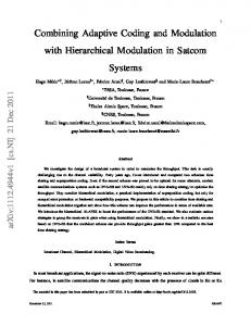
An application of distributed simulation and the HLA is in the development of systems of systems simulation. This class of simulation uses federates to model the subcomponents of a system. The federates interact within a federation to simulate the entire system. Figure 1.1 illustrates the systems of systems approach to simulation. A problem occurs in this type of simulation when there is a requirement for modelling multiple systems within a federation. This situation is illustrated in Figure 1.2. A federate modelling a subcomponent of Systemj needs to be able to determine whether received data was generated by another
SC1
... SC2
SCn
RTI
Figure 1.1. Systems of Systems Federation. The boxes noted with SCi represent federates modelling the subcomponents of the complete system.
System1 SC11
System1
System2 SC21
...
SCn1
SC12
SC22
...
SCn2
SC11
System2 SC21
...
SCn1
SC12
RTI1
SC22
...
SCn2
...
SCnm
RTI2
RTI
Inter-system communication
RTIm ...
SC1m
SC2m
...
SCnm
Systemm
...
SC1m System
SC2m
m
Figure 1.2. Multiple System Federation. subcomponent of Systemj rather than a subcomponent of Systemi , (i 6= j). A project utilising this systems of systems approach to simulation is the Virtual Maritime System (VMS) [1]. The goal of the VMS is to develop an architecture to enable maritime simulations where individual platforms are represented as a collection of subcomponents. In the VMS the overall system being simulated is a maritime platform. The subcomponents model the components onboard the platform. To illustrate, an application of the VMS is to simulate the operations of a warship. The federates within this federation simulate components of the warship such as the motion of the ship, the sensors onboard the ship, the track data the sensors generate in response to detecting targets and the systems used to control the operations of the ship. The multiple system federation illustrated in Figure 1.2 manifests itself in the VMS as a federation modelling multiple platforms. The problem of data containment is illustrated by considering the track data generated by the sensors attached to a platform. The track data generated by a sensor, in response to detecting a target, is processed by a command and control system attached to the same platform. However, within a single federation it is possible for the federate modelling the command and control system to receive track data generated by sensors attached to other platforms. This requires the federate modelling the command and control system to be able to filter track data received in order to only process those tracks generated by sensors attached to the same platform. A solution to the data containment problem requires an identifier to be attached to data generated (this is the approach employed by the VMS). This identifier indicates the system to which the subcomponent is attached, and can be used for filtering purposes. Another solution is provided by the Data Distribution Management (DDM) services provided by the HLA. A routing space can be defined which can be divided into regions based on system identification.
Figure 1.3. Multiple System Federation Community.
System9 System7 System6 System1
System8 System2
System3
System4
System5
Figure 1.4. Multiple System Hierarchical Federation Community.
Internal system data is then communicated through the appropriate system region. A third solution, and the solution discussed in this paper, requires the simulation of one system in a federation. Collaboration between systems is then achieved via collaboration between federations. This allows data intrinsic to a system to be contained within a federation, with only necessary data communicated to other federations. This collaboration of federations is referred to as a federation community [2]. This approach is illustrated in Figure 1.3. It is possible for the systems simulated within the federations to be subcomponents of higher order systems. Thus, a set of federations can be grouped to form a higher order system, with further grouping supporting simulation of the collaboration between these higher order systems. Continuing this grouping forms a hierarchical structure, and this structure is therefore termed a hierarchical federation community. This is illustrated in Figure 1.4. This approach also has benefits beyond those of data containment. If a simulation is to be executed across a wide area network (WAN), federations can be contained within local area networks (LAN) at the extents of the WAN. This allows internal system data to be contained within the LANs as opposed to the single federation cases where the
internal system data is communicated across the WAN only to be potentially filtered at the receiving end. Use of heterogeneous object models and runtime infrastructures (RTIs) across the federations of the federation community is possible. These benefits come at the cost of defining and implementing an architecture to support hierarchical federation communities. An aspect of the hierarchical federation community architecture is the support for time management, in particular the causal ordering of messages across the hierarchical federation community. This is the focus of this paper. Section 2 provides a description of the architecture being developed to support hierarchical federation communities. Section 3 discusses the time management aspect of the hierarchical federation community architecture. Section 4 discusses extensions to the the time management algorithms designed to enhance functionality and performance.
2
Federation Communities
Various architectures and applications have been defined for federation communities. The Security Guard Federate [3] utilised federation communities to allow federations executing at different security levels to interoperate. This application led to the work aimed at the development of an architecture for the general interoperation of federations, known as the High Level Architecture’s Bridge Federate [4, 5]. Briggs [6] proposes the development of a gateway standard for RTI interaction as a means of achieving interoperability between federations. In this approach, multiple, distributed RTIs would appear as a single RTI, with the RTIs sharing state data via the gateway standard at execution time. Hierarchical federation communities have been discussed previously. Magee [7] introduces a number of architectures for achieving hierarchical federation communities and discusses in greater detail an approach that requires the development of a custom RTI. Susumu [8] discusses the notion of a multiport federate (MPF) where a federate already modelling a component of the simulation is utilised as the connector between federations, rather than requiring the development of a custom federate to perform the joining of federations. A time management strategy for use in a MPF federation community is also presented. Lake [9] presents an architecture whereby there are multiple paths of communication between federations. A time management strategy over such an architecture is also pre-
Federate Proxy
RTI Federation
RTI Federation
RTI Federation
Figure 2.5. The Federate Proxy architecture for linking federations.
sented. The time management algorithms in both Susumu and Lake require the provision of services outside those provided by the HLA standard. Myjak [2] presents the results of a study group looking at the issue of RTI interoperability, ie, inter-federation communication. The term federation community is introduced and four architectures of federation communities are defined based on the homogeneity or heterogeneity of the object models and RTIs used by the constituent federations. Four architectures for achieving federation interoperability are presented and given the names Federate Gateway, Federate Proxy, RTI Broker and RTI Interoperability Protocol. The simplest architecture for providing inter-federation communication is the Federate Proxy [2]. A Federate Proxy is a federate that is concurrently joined to two or more federation executions. As the name states, a Federate Proxy, with respect to a local federation, acts as proxy for all remote federations and all data generated by remote federations appears to have been sourced by the Federate Proxy. The Federate Proxy may also be responsible for the filtering of data to destination federations. The Federate Proxy is illustrated in Figure 2.5. When operating as a data filter, the Federate Proxy may not be the ideal architecture when the simulation is geographically dispersed. As the Federate Proxy is a single process application it can be local to at most one federation, thus, data generated by remote federations traverse the potentially large distances between LANs only to filtered; the same situation as for the single federation simulation. The notion of distributing the Federate Proxy and having a component local to each federation is briefly introduced in Magee [7]. Cramp and Oudshoorn [10] introduce the term Distributed Federate Proxy (DFP) for this architecture and extend its scope to support hierarchical federation communities. It is the architecture of the DFP for which the time management algorithm of Section 3.2 is defined. Section 2.1 presents the DFP architecture for reference.
Distributed Federate Proxy Sim Node
Sim Node
DFPC
DFPC
DFPC
RTI Federation
RTI Federation
RTI Federation
Figure 2.6. Distribute Federate Proxy architecture for hierarchical federation communities.
2.1 Distributed Federate Proxy
The DFP architecture is illustrated in Figure 2.6. The original Federate Proxy is divided into components executing local to each federation. These components are termed Distributed Federate Proxy Components (DFPC). The DFPCs are interconnected via a tree of nodes (SimNodes) forming the hierarchical federation community. Note that Figure 2.6 shows a binary tree, however, the DFP architecture imposes no constraints on the structure of the hierarchical federation community. The tree structure of the DFP architecture is driven by the application. Each SimNode represents the root of a sub-federation community. A SimNode is responsible for managing the communication between it’s connected child nodes and also between it’s connected child nodes and it’s parent node (if it exists). Such management may include data filtering and/or data transformations. A unique feature of the DFP architecture is that all communication in the simulation hierarchy is achieved via the services defined in the HLA federate interface specification, specifically the services defined in the IEEE standardised version of the HLA [11, 12, 13]. The services defined in the HLA interface specification can be partitioned into two groups based on who invokes the service; the federate or the RTI. A federate invokes services on an RTI via the notion of an RTI ambassador. Similarly, the RTI invokes services on a federate via the notion of a federate ambassador. Thus, a SimNode presents the RTI ambassador services to it’s children. Similarly, the children of a SimNode present the federate ambassador services to their parent SimNode.
Communication up the simulation hierarchy is via the RTI ambassador services and communication down the hierarchy is via the federate ambassador services. An exception to this rule is the DFPCs. A DFPC is connected to a parent SimNode and to the RTI that is executing the federation which the DFPC is representing to the rest of the federation community. Thus, a DFPC receives federate ambassador callbacks from it’s parent SimNode which may need to be converted to RTI ambassador service invocations on the RTI within which it’s federation is executing. By enabling communication via the services defined in the HLA federate interface specification, federates can be written, utilising the standard interface specification, to join at any level of the simulation hierarchy. This feature provides the potential for concurrently simulating at multiple levels of fidelity. Lower levels of the simulation architecture could be executing at a high fidelity while higher levels are executing based on an aggregation of the lower level components. It is the time management services implemented by the individual components of the DFP simulation architecture that provide the means for controlling the time advances and causal delivery of time stamped messages for all federates in the hierarchical federation community.
3
Time Management
A physical system to be simulated has some aspects of its state dependent on time. Simulation time is an abstraction used by a simulation to represent physical time [14]. Time management in a simulation refers to controls put in place to advance time and to order and deliver messages that have temporal state. In a single process simulation, management of time is relatively simple. A distributed simulation introduces complexities to the time management process due to the non-determinism in the ordering of messages received by a distributed component in relation to the order in which they were sent. Section 3.1 provides a definition of the time management policies used by the HLA. In particular, the time management policy providing for conservative, time stepped simulation is discussed. It is this class of time management that is used in the description of the time management algorithms presented in Section 3.2 (event stepped simulation is discussed in brief in Section 4). The notation used to describe the HLA time management process in Section 3.1 is extended upon in Section 3.2 to describe the time management policies developed for use in hierarchical federation communities, specifically in the DFP architecture defined in Section 2.1.
3.1 In HLA Time management in the HLA is defined in Fujimoto [15]. The time management services defined by the HLA provide for several different time management policies. Perhaps the main policy used is that of conservative time management. Conservative time management requires the removal of the nondeterminism in the delivery of temporal messages. This is achieved in the HLA through federates making requests to advance time of a time authority, and having those requests granted only when it is guaranteed that temporal messages can not be received in the federates past. The rest of this section describes this process in more detail. A federation is defined by a set of federates, an RTI within which the federation executes and a federation object model. Let the set of federates joined to a federation be denoted by F . Let fi denote the federates within F , with i ∈ [1, n] and |F | = n (ie, there are n federates in F ). Let the RTI within which the federates of the federation execute be denoted by RT I F . Each federate fi ∈ F has two time parameters. These are the federate time and a lookahead value. The lookahead value of a federate provides a contract between the federate and the rest of the federation that the earliest possible timestamp associated with an outgoing message will be greater than or equal to the federates current time plus its lookahead. As a lookahead is associated with sending time stamped messages, only federates that are able to send time stamped messages (time regulating federates) have a valid lookahead value. A lookahead value of ∞ can be assigned to non-time regulating federates. It is possible to calculate a third time parameter for the federates. The lower bound on time stamp (LBTS) for a federate indicates the earliest time stamp that can be associated with a message yet to be received by that federate. This constrains the time advances of a federate to ensure the federate’s time does not exceed the time stamp of a potential message reception. Only those federates that are capable of receiving time stamped messages (time constrained federates) have a valid LBTS. An LBTS of ∞ could be calculated for non time constrained federates, which provides no constraint on time advances. F can be partitioned into four disjoint sets based on the time management policies employed by the federates. Let FRC denote the set of federates that are time regulating and time constrained. Let FR denote the set of federates that are time regulating only. Let FC denote the set of federates that are time constrained only. Finally, let FN denote the set of federates that are neither time regulating nor time constrained. It is useful to define the set of all time regulating federates as the union of FRC and FR . Let FAR = FRC ∪ FR denote the set of all time regulating fed-
erates. Similarly, the set of all time constrained federates is defined as the union of FRC and FC . Let FAC = FRC ∪FC denote the set of all time constrained federates. For a federate fi ∈ F , define the operators T ime(fi ), Lookahead(fi ) and LBT S(fi ). These operators obtain the current time, lookahead and LBTS parameters, respectively, of federate fi . The are also allowed to appear on the left hand side of an assignment expression for the intention of setting the respective parameter. These operators allow for the calculation of LBTS for a federate fi ∈ FAC as shown in Equation 1.
LBT S(fi ) = min(T ime(fj ) + Lookahead(fj )) ∀fj ∈ FAR , j 6= i.
(1)
The time advances of a federate in a federation need to be controlled in order to achieve the causal delivery of messages. This control is provided by the RTI. The basic time management cycle of a federate fi ∈ F is:
1. fi requests a time advance of RT I F to a time t. Upon invocation of this request, federate fi guarantees that any messages generated, M , will have a time stamp, T S(M ), greater than or equal to the time requested plus the federate’s lookahead, ie, federate fi guarantees that T S(M ) ≥ t + Lookahead(fi ). 2. RT I F delivers, potentially zero, messages to fi . A message M delivered to fi is guaranteed to have a time stamp T S(M ) less than or equal to the value of the time advance request t, ie, federate fi receives messages such that T S(M ) ≤ t. 3. RT I F grants a time advance of t to federate fi . RT I F issues the time advance grant when it can guarantee that federate fi will receive no more messages with time stamp less than or equal to t. This condition is met when LBT S(fi ) exceeds the value requested in the time advance, t. A federate’s LBTS value increases in response to time advance requests issued by other federates to RT I F . Thus, RT I F grants a time advance of t to federate fi when LBT S(fi ) ≥ t.
The process described in this section provides for the causal delivery of time stamped messages. The next section describes how this is achieved in a hierarchical federation community based on the DFP architecture of Section 2.1.
3.2 In Hierarchical Federation Communities Time management in federation communities needs to provide for the causal delivery of messages between federates in different federations. How this is achieved is dictated by the architecture used to provide communication between the federations. The time management process described in this section is defined for the Distribute Federate Proxy architecture presented in Section 2.1. The time management process is discussed in two sections. First, Section 3.2.1 discusses the constraints imposed by the DFP architecture for achieving correct temporal delivery of timestamped messages and causal ordering of those messages. Section 3.2.2 discusses the time management process used by the components of the DFP architecture that achieves the constraints.
3.2.1
Constraints
Consider a federation community containing m federations. Let F j denote the set of federates joined to federation j ∈ [1, m]. A federate within federation j can be represented as fij , ie, the ith federate of federation j. In the DFP architecture there is a DFPC connected to each federation. Let the DFPC connected to federation j be denoted by DF P C j . The DFPCs connected to federations are the entry and exit points for messages communicated between federations. In order for DF P C j to be able to receive time stamped messages from federation j it must be time constrained. Similarly, in order for DF P C j to be able to send time stamped messaged to federation j is must be time regulating. Hence, we have the first requirement for time management in the DFP architecture, all DFPCs must be time regulating and time constrained. This requirement makes the assumption that there exists at least one federate connected to federation j that is time regulating and at least one federate connected to federation j that is time constrained. If there is no time regulating federate, no timestamped messages can be generated, and there is no need for the DFPC to be time constrained. Similarly, if there is no time constrained federate, there is no federate capable of receiving time stamped messages and hence the DFPC need not be time regulating. This assumption and its impact on the time management of the DFP architecture is discussed further in Section 4. Suppose there is a message path between federation i and federation j. The DFPCs connected to each federation, DF P C i and DF P C j , act as the agents for message communication between the federations. In order for
a time stamped message generated within federation i to be causally delivered to federation j, the condition presented in Equation 2 must be met at all points in time.
LBT S(DF P C i ) ≥ T ime(DF P C j ) +Lookahead(DF P C j ) (2) The value LBT S(DF P C i ) indicates the earliest possible timestamp that can be associated with a message generated by a federate fij ∈ F j . The value T ime(DF P C j ) + Lookahead(DF P C j ) indicates the minimum timestamp that DF P C j can associate with a message sent to federation j. Thus, the condition states that for all possible timestamps associated with messages generated by federation i, DF P C j must be able to assign that timestamp to a message sent to federation j. In general, messages generated by federation j can be passed to federation i. Thus, the condition of Equation 3 must hold simultaneously with Equation 2.
LBT S(DF P C j ) ≥ T ime(DF P C i ) +Lookahead(DF P C i ) (3) Considering the federation community as a whole (a set of m federations), there exists the potential for a message generated by any federation to be passed to any other federation. Let DF P C ALL denote the set of all DFPCs in the federation community, ie, DF P C ALL = {DF P C i : ∀i ∈ [1, m]}. For time causality to be assured across the entire federation community, Equation 4 must hold for each DF P C i ∈ DF P C ALL simultaneously.
LBT S(DF P C i ) ≥ T ime(DF P C j ) +Lookahead(DF P C j ) ∀j ∈ [1, m], i 6= j (4) A DFPC is connected to an RTI and to a SimNode. The SimNode essentially provides the functionality of an RTI. Thus, a DFPC has time state with respect to the SimNode as well as with the RTI. This implies that the DFPC must be time regulating and time constrained with respect to the SimNode (timestamped messages need to be sent to and received from the SimNode). Again the assumption is made that there exists a time regulating federate and a time constrained federate joined to the same federation as the DFPC.
This structure also allows for the development of another condition to ensure causal ordering of messages. In the discussion on the development of the conditions that follow, an expression {x(DF P C)}RT I refers to the operator x applied to the DF P C with respect to the RTI to which it is connected. Similarly, the expression {x(DF P C)}SN refers to the operator x applied to the DF P C with respect to the SimNode to which it is connected. A message M with timestamp T S(M ) received from the RTI by a DFPC needs to be passed on as a message with the same timestamp to the SimNode. In order for this to occur, the condition T S(M ) ≥ {T ime(DF P C) + Lookahead(DF P C)}SN must be met. In order for this condition to hold for all possible time stamped messages, it must hold for the minimum possible timestamp assigned to a message. The minimum timestamp assignable is given by LBT S(DF P C)RT I . Thus, the previous condition for a single message can be generalised to a condition on the DFPC for all potential timestamped messages received by the DFPC from the RTI, as shown in Equation 5.
{LBT S(DF P C)}RT I
≥
{T ime(DF P C) (5) +Lookahead(DF P C)}SN
At the same time, the same condition needs to hold in the opposite direction of message flow, ie, messages received from the SimNode and forwarded to the RTI. This condition is given in Equation 6.
{LBT S(DF P C)}SN
≥
{T ime(DF P C) (6) +Lookahead(DF P C)}RT I
It now remains to consider the time management processing of a SimNode. As has been discussed previously, a SimNode presents the RTI ambassador services to the components (federates, DFPCs and other SimNodes) connected to it. Additionally, a SimNode itself may connect to another SimNode (the only SimNode that does not connect to another SimNode exists at the root of the simulation architecture tree). Let SN denote the SimNode under discussion. Let SN P denote the SimNode to which SN is connected (assuming for the moment that SN is not at the root of the DFP). The superscript P refers to the parent of the specified node. Let SN C denote the set of components connected to SN . The superscript C refers to the children of the specified node. Let SNiC be an element of the set SN C , ie, one
of the components connected to SN C . Assume that there are n such components, ie, SN C = {SNiC : ∀i ∈ [1, n]}. SN needs to be able to send timestamped messages to SN P and receive timestamped messages from SN P . Thus, SN is time regulating and time constrained. Causal delivery of messages from SN P is guaranteed as SN P implements the time management process for a single federation as described in Section 3.1 with one exception that is described shortly. Correct temporal delivery of a message M with timestamp T S(M ) is possible if T S(M ) ≥ T ime(SN ) + Lookahead(SN ). M is sourced from the elements of SN C . The minimum possible timestamp associated with M is given by LBT S(SN C ) = min(T ime(SNiC ) + Lookahead(SNiC )); ∀i ∈ [i, n]. As SN provides the time management for the elements of SN C , the value LBT S(SN C ) is readily available. With these values it is possible to define a constraint on T ime(SN ) that is similar to Equation 5. This constraint is provided in Equation 7.
LBT S(SN C ) ≥ T ime(SN ) +Lookahead(SN )
(7)
The constraint of Equation 7 is valid for all SimNodes in the DFP architecture, except for the root of the architecture which has no time or lookahead value. The message delivery process of the root SimNode is exactly as provided by an RTI in a single federation, as discussed in Section 3.1. Assume the components connected to SN , the elements of SN C , are SimNodes only. Let SNjC be the element of SN C for which LBT S(SN C ) = T ime(SNjC ) + Lookahead(SNjC ). Making this substitution into Equation 7 gives:
T ime(SNjC ) + Lookahead(SNjC ) ≥ T ime(SN ) + Lookahead(SN ). As SNjC is a SimNode, Equation 7 can be reapplied to obtain:
LBT S((SNjC )C ) ≥ T ime(SNjC ) + Lookahead(SNjC ) ≥ T ime(SN ) + Lookahead(SN ) where (SNjC )C is the set of components connected to
SimNode SNjC . This argument can be reapplied to the elements of (SNjC )C and so on until a DFPC is reached. When SNjC is a DFPC, say DF P C i , Equation 7 becomes {T ime(DF P C i ) + Lookahead(DF P C i )}SN ≥ T ime(SN ) + Lookahead(SN ). Using Equation 5 in the previous relation gives:
{LBT S(DF P C i )}RT I ≥ {T ime(DF P C i ) + Lookahead(DF P C i )}SN ≥ T ime(SN ) + Lookahead(SN ). Starting at the root SimNode of the DFP architecture, call it SN ROOT , and applying the previous argument through to a particular DFPC, say DF P C i , the relation {LBT S(DF P C i )}RT I ≥ LBT S(SN ROOT ) holds, where LBT S(SN ROOT ) = LBT S((SN ROOT )C ). It is possible to apply the same argument along all paths from SN ROOT to all DFPCs. Thus, the previous relation can be stated generally for all DFPCs, which is given in the relation of Equation 8.
{LBT S(DF P C i )}RT I ≥ LBT S(SN ROOT ) ∀DF P C i ∈ DF P C ALL
A DFPC is a transit point for messages to and from the federation to which the DFPC is connected. Consider DF P C i connected to RT I i and SimNode SN . DF P C i has time advance responsibilities to both RT I i and SN . The time advance request loop for DF P C C is: 1. Request time advance of SN to time t = {LBT S(DF P C i )}RT I − {Lookahead(DF P C i )}SN . After the request is made, DF P C i guarantees not to send a timestamped message with timestamp = TS < t + {Lookahead(DF P C i )}SN {LBT S(DF P C i )}RT I to SN . 2. Request time advance of RT I i to time t = {LBT S(DF P C i )}SN − {Lookahead(DF P C i )}RT I . After the request is made, DF P C i guarantees not to send a timestamped message with timestamp T S < t + {Lookahead(DF P C i )}RT I = {LBT S(DF P C i )}SN to RT I i .
(8)
As Equation 8 is true for all DFPCs in the DFP architecture, it is true for the DF P C j , where:
{LBT S(DF P C j )}RT I = min({LBT S(DF P C i )}RT I ) ∀DF P C i ∈ DF P C ALL . j
The value {LBT S(DF P C )}RT I is the earliest possible timestamp assigned to a message generated by a federate in the entire federation community. Thus, LBT S(SN ROOT ) is at most the earliest possible timestamp assigned to a message generated by any federate in the entire hierarchical federation community. This implies that all time advance decisions are made by SN ROOT .
3.2.2
such that the conditions are met. The time management process refers to the sequence and values of time advance requests issued by DFPCs and SimNodes. The time management process of a SimNode also refers to the decision process as to when a time advance request is granted.
Time Management Process
The previous section discussed conditions for the causal delivery of messages in a DFP structured hierarchical federation community. This section discusses the time management process of the components of the DFP architecture
During the request of step 1 above, DF P C i receives timestamped messages from SN with timestamps T S ≤ t. The earliest possible timestamp associated with a received message is {LBT S(DF P C i )}SN . Thus, the range of valid timestamps associated with received messages is T S ∈ [{LBT S(DF P C i )}SN , t]. Step 2 guarantees that messages with this range of timestamps are deliverable to RT I i . This satisfies the constraint of Equation 6. A similar argument can be made for messages sourced from RT I i and sent to SN , satisfying the constraint of Equation 5. Messages delivered to a non-root SimNode are delivered by the SimNode to the other child components connected to it and to it’s parent SimNode (unless the message was received from the parent) for forwarding to the rest of the federation community. Consider a component (DFPC, SimNode or federate) (SNjC )C i making a time advance request of the SimNode it is connected to, SNjC . In turn, SNjC is connected to SimNode SN . The time advance process is provided below: 1. (SNjC )C i requests time advance to t of SimNode SNjC .
2. SNjC recalculates the LBTS value for each C C (SNjC )C k ∈ (SNj ) . 3. SNjC records the request and in turn makes a time advance request to SN of time LBT S((SNjC )C ) − Lookahead(SNjC ). Note that t ≥ LBT S((SNjC )C ). 4. When SNjC is granted the time advance to LBT S((SNjC )C )−Lookahead(SNjC ), SNjC grants all pending requests to time T for which T ≤ LBT S(SNjC ) − Lookahead(SNjC ). SNjC is capable of performing causal delivery of messages to the components connected to it via the implementation of the time management process of an RTI for a single federation, as described in Section 3.1. An addition needs to be made to the process to allow for the delivery of messages generated by components not connected to SNjC . These messages are delivered via SN and are obtained during the time advance request of step 3 above. The value of this time advance request ensures that any received messages can be sent to the component with the minimum time value and satisfies the condition of Equation 7 for delivery of messages to SN . This process is performed recursively up the tree until the root of the DFP architecture is reached. The final component to consider is the root of the DFP architecture. The time management process employed by the root SimNode, SN ROOT is the terminal case of the recursion stated for the time management process of the internal SimNodes. As stated in the previous section, the time management process is analogous to the process employed by an RTI in a single federation. Thus, the process described in Section 3.1 is valid and summarised here. ROOT 1. (SN ROOT )C . i requests time advance to t of SN
2. SN ROOT recalculates the LBTS value for each SNjC ∈ (SN ROOT )C . 3. SN ROOT grants a request to (SN ROOT )C i when t ≤ LBT S((SN ROOT )C ). i This process provides valid time management for the components connected to SN ROOT . These components can comprise of DFPCs, internal SimNodes and federates. The time management process for DFPCs and SimNodes have also been presented in this section. It can be developed by induction that since the time management process of the root of the DFP architecture is correct and that the time management process of the internal SimNodes is correct
and that the time management process of the DFPCs is correct, the time management process of the entire DFP architecture is correct.
4
Extensions
The time management process presented in Section 3.2 can be extended in a number of ways. Event stepped simulation is not considered for federates connected directly to SimNodes (federates connected to the RTIs of the federations can still utilise event stepped simulation). To allow event stepping by federates connected to SimNodes, the time advance grant decision process of the SimNodes needs to be modified. An implicit assumption has been made that all messages generated by a federate fij (the ith federate of the j th federation) needs to be communicated to all other federates in the entire federation community. This may not be the case. The declaration management services defined by the HLA Federate Interface Specification provide information as to which federates require what data. Utilising this information may allow the determination that a certain message does not need to traverse beyond a certain point in the DFP architecture, potentially allowing for a faster time advance grant to be issued. Another assumption that has been made is that at least one federate in each federation is time regulating and at least one federate in each federation is time constrained. This forces the requirement that all components of the DFP architecture to be time regulating and time constrained. If this assumption does not hold, the time management process may be optimised by pruning certain sections of the DFP architecture that are not interested in receiving timestamped messages or cannot generate timestamped messages.
5 Conclusion Hierarchical federation communities offer a unique means for performing distributed simulation. The hierarchical structure of these federation communities make them natural frameworks for performing simulations of physical systems that have an inherently hierarchical nature. However, a simulation architecture needs to be developed that provides correct operation between remote federations. In particular, the correct temporal and causal delivery of messages between federations.
The Distribute Federate Proxy (DFP) provides an architecture for the interconnection of federations in a hierarchical manner. Communication between federations in the DFP architecture is performed via hierarchically related distributed components within the architecture. A unique feature of this architecture is that communication between the components is performed via the services defined in the HLA Interface Specification. This paper has presented necessary constraints on the components of the DFP architecture in order for correct temporal and causal ordering of messages to take place in the DFP enabled hierarchical federation community. A process that achieves the stated constraints for each class of component in the architecture is also presented. It is surmised that if each of the components achieves their stated constraints for correct time management, the entire DFP architecture performs correct time management.
References [1] John P. Best, Shane A. Canney, and Anthony Cramp. The Virtual Maritime System Architecture. In Simulation Interoperability Workshop Fall 2002, Orlando, Florida, September 2002. [2] Michael D. Myjak, Duncan Clark, and Tom Lake. RTI Interoperability Study Group Final Report. In Simulation Interoperability Workshop Fall 1999, Orlando, Florida, September 1999. [3] Jarrellann Filsinger. HLA Security Guard Federate. In Simulation Interoperability Workshop Spring 1997, Orlando, Florida, March 1997. [4] Wesley Braudaway and Reed Little. The High Level Architecture’s Bridge Federate. In Simulation Interoperability Workshop Fall 1997, Orlando, Florida, September 1997. [5] Christina Bouwens, Daphne Hurrell, and David Shen. Implementing Ownership Management Services With a Bridge Federate. In Simulation Interoperability Workshop Spring 1998, Orlando, Florida, March 1998. [6] Keith Briggs. A Required RTI Gateway Standard as a Solution to RTI Interoperability. In Simulation Interoperability Workshop Spring 1998, Orlando, Florida, March 1998. [7] Gerry Magee, Graham Shanks, and Pete Hoare. Hierarchical Federations. In Simulation Interoperability Workshop Spring 1999, Orlando, Florida, March 1999.
[8] Susumu Ninomiya et al. Hierarchical MultiFederation Structure of the Sensor Data Fusion Simulation in JUSA. In Simulation Interoperability Workshop Fall 1998, Orlando, Florida, September 1998. [9] Tom Lake. Time Management over Inter-Federation Bridges. In Simulation Interoperability Workshop Fall 1998, Orlando, Florida, September 1998. [10] Anthony Cramp and Michael Oudshoorn. Employing Hierarchical Federation Communities in the Virtual Ship Architecture. In Twenty-Fifth Australasian Computer Science Conference, pages 41–50, Melbourne, Australia, January 2002. [11] The Institute of Electrical and Electronics Engineers, Inc. IEEE Std 1516-2000. IEEE Standard for Modeling and Simulation (M&S) High Level Architecture (HLA) - Framework and Rules, December 2000. [12] The Institute of Electrical and Electronics Engineers, Inc. IEEE Std 1516.1-2000. IEEE Standard for Modeling and Simulation (M&S) High Level Architecture (HLA) - Federate Interface Specification, December 2000. [13] The Institute of Electrical and Electronics Engineers, Inc. IEEE Std 1516.2-2000. IEEE Standard for Modeling and Simulation (M&S) High Level Architecture (HLA) - Object Model Template (OMT), December 2000. [14] Richard M. Fujimoto. Parallel and Distributed Simulation Systems. Wiley Inter-Science, 2000. [15] Richard M. Fujimoto. Time Management in the High Level Architecture. Simulation, 71(6):388–400, 1998.
Author Biographies ANTHONY CRAMP is the Technical Lead, High Level Architecture, in the Surface Ship Combat Systems Group, Defence Science and Technology Organisation. He holds a Bachelor of Computer Engineering with First Class Honours and a Bachelor of Computer Science both from the University of Newcastle, Australia. He has worked with the DSTO and the Virtual Maritime System since 1999 and is currently undertaking a PhD at the University of Adelaide looking at the development of hierarchical federation communities for simulation. MICHAEL J. OUDSHOORN completed his PhD at the University of Adelaide in 1992. He is an Associate Professor in the School of Computer Science at the University
of Adelaide, as well as the Associate Dean (International) for the Faculty of Engineering, Computer and Mathematical Sciences. His research interests include concurrent and distributed systems, software engineering and compiler construction. He is an active member of the Australian Computer Society, ISCA, ACM and the IEEE. He serves on numerous conference program committees and journal editorial boards. JOHN P. BEST is Head, Surface Ship Combat Systems Group, Defence Science and Technology Organisation (DSTO). He holds a Bachelor of Science degree with First Class Honours in Physics from the University of Queensland, and a PhD in Applied Mathematics from the University of Wollongong. In 1998 he initiated DTSO’s Virtual Ship (later Virtual Maritime System) project, leading development of the underlying simulation architecture. In his current role he leads a group that undertakes analysis in support of combat system acquisition, development and support. A principal component of the group’s effort is use of synthetic environments to enable human-in-the-loop experimentation.