Tip Position Control of a Flexible-Link Arm A. Arisoy*, M. Gökasan ** and O.S. Bogosyan *** * **
Turkish Air Force Academy/Dept.of Electronics Eng., Istanbul, TURKEY Istanbul Technical University/ Dept.of Electrical Eng., Istanbul, TURKEY ***University of Alaska Fairbanks/ ECE Dept., Fairbanks, Alaska, USA
[email protected] [email protected] [email protected]
Abstract— Partial Feedback Linearization (PFL) control method is applied to a single Flexible Link Arm (FLA) with payload. A feedback linearization based controller is designed to achieve set point positioning control. Flexible robot arms have structural flexibilities and resulting high number of passive degrees-of-freedom. They cannot be decoupled due to the highly nonlinear structure. Since exact feedback linearization control methods cannot be applied to these systems. Partial feedback linearization control methods are suitable for the flexible systems. For set-point control, collocated PFL control is applied to achieve the desired hub unit position and non-collocated PFL control algorithm is applied consecutively using switching action to improve the tip-position precision of a single FLA as demonstrated by simulations. Numerical simulations of a single FLA successfully demonstrate the effectiveness of the proposed method.
I. INTRODUCTION Over the last decade, the modeling and control of lightweight flexible-link manipulators have been challenging research topics with the objective of improving the robot performance. The lightweight requirement gives rise to problems with structural flexibilities. Lightweight and low mass restrictions put a limitation on the degree of rigidity. Hence control design needs to be taken consideration flexibility [1]. Flexible Link robots have highly nonlinear and coupled dynamics. They cannot be decoupled due to the highly nonlinear structure. Hence, exact feedback linearization control methods cannot be applied to these systems. However, partial feedback linearization (PFL) control methods are suitable flexible systems that has passive degree-of-freedom. For Flexible Link robots it is known that the portion of the dynamics corresponding to the actuated (active) degrees of freedom may be linearized by nonlinear feedback. The remaining portion of the dynamics after such partial feedback linearization is nonlinear and represents internal dynamics. Under Strong Inertial Coupling condition, alternatively, it is possible to linearize the portion of the dynamics corresponding to non-actuated (passive) degrees of freedom [2]. Spong applied this method to acrobat, of which dynamics are not feedback linearizable with static feedback and nonlinear coordinate transformation [3] for swing-up control problem. In the present study, partial feedback linearization control method is applied to a single flexiblelink robot arm. There have been quite a number of studies deals with stabilization and tracking control of flexible robot manipulators. Various methods have been developed and tested by simulations and/or experiments. Among studies
in the last decade, Khorrami, Jain & Tzes [4] developed input-shaping techniques; Yang, et al. [5] applied adaptive control; Yang, Krishnan & Ang applied output redefinition methods [6]. Gokasan, Bogosyan, Sabanovic&Arabyan applied sliding mode method as observer and controller for a single link flexible arm in their study [7]. Most research in the literature has concentrated on the control of a single flexible link. The dynamic model used by almost all of the researchers is the Euler-Bernoulli model of a beam, with a fourth order equation that leads to an originally infinite-dimensional model of a flexible link. The angle of rotation of the link is the common collocated output for trajectory tracking of a single flexible link; however, the performance of this output measurement is not very satisfactory, as it provides only a weak control of the link vibrations [8]. This has initiated research using noncollocated output measurements, such as the tip position of the link. However, the problem with this choice is that it leads to a non-minimum phase zero dynamics. Olfati-Saber [9] studied proposing noncollocated outputs for the flexible based on the angle of rotation augmented with a generalized saturated weighted linear combination of the deformation amplitudes of the link, also proving that the corresponding zero-dynamics is minimum phase [10]. Chen & Fukuda also demonstrate the performance improvement achieved with the control of the noncollocated output [11]. Rokui and Khorasani considered the problem of indirect adaptive control of a single-link manipulator based on a discrete-time nonlinear model of the system without gravity effects. The output redefinition strategy is employed so that the resulting map between the hub angle and the new output is guaranteed to be minimum phase [12]. In the present study, the EulerBernoulli model of a beam is used as dynamic model for the flexible-link robot arm with a fourth order equation and assumed to be able to rotate by arbitrary amount and at arbitrary rate in the vertical plane under the action of gravity. Collocated and noncollocated PFL formulation is employed to derive the control input equations for collocated and noncollocated output definition of the flexible-link arm. The use of flexible links in a robot inevitably causes the elastic deformation and vibration of the endpoint of the robot during high-speed operations. The deflection and vibration will tend to degrade the positioning performance of the robot. To overcome these problems, the deformation and oscillation information [13] has been considered during the controller design and based on the tip deflection feedback, a non-linear Lyapunov-type control scheme presented for the single flexible-link robot arm set-point and trajectory-tracking control. Choi and Cheon proposed to a sliding mode controller with
disturbance estimator using the theory of variable structure system (VSS) to enhance the vibration control performance of a single flexible-link arm subjected to torque disturbances. In their study, state-space flexiblelink dynamic model, which is Euler-Bernoulli beam theory with assumptions; small deflections, small angular velocities and neglecting axial deflections, has been used to be considered the horizontal motion without gravity effects [14]. It is a challenging objective to suppress the dynamic vibration modes of the flexible-link robot arm and simultaneously to regulate the hub’s angular position to the desired angle of rotation in the given time. In the present study, the switching control has been applied to achieving stability and improving vibration control performance of the flexible-link arm. The switching control has special advantage for control of dynamic systems whose smooth control does not exist, such as some underactuated mechanical systems. This process involves specification of the family of feedback functions and switching logic. The switching values are calculated in real-time. Then suitable control input is applied to the plant. Tarn et al. addressed in their article, a sensorreferenced control method using positive acceleration feedback together with a switching control strategy for robot impact control and force regulation [15]. Xi et al. Proposed a systematic control design procedure to construct a switching robust nonlinear control law which not only solves the global exponential regulation problem, but also Lyapunov stability problem for a class of nonholonomic chained systems with strongly nonlinear/state driven disturbances and drifts [16]. Zhang and Tarn presented the switching control that has been applied for feedback stabilization of the Pendubot [17] and also presented a hybrid switching control strategy for nonlinear and underactuated mechanical systems [18]. In this study, the controller consists of a collocated or noncollocated nonlinear PFL functions and a supervisor, the supervisor is based on hub’s angular position setting time. Up to the desired angle of rotation in the given time, collocated PFL control algorithm is applied and then switching manipulation selects a noncollocated PFL control algorithm applied to control the system. This study proposes a methodology for designing stable manipulation-variable partial feedback linearizing controls of a single flexible link robot arms for positioning control. Additionally, switching controller is designed using collocated and noncollocated PFL to improve precision of tip position for FLA. Proposed algorithms are verified by using computer simulations. II.
DYNAMIC MODEL OF THE FLEXIBLE LINK
In this study, due its wide range of applications in space robotics, the control of a single flexible link robot manipulator is investigated with the consideration of a payload at the tip. The dynamic model is derived using Euler-Bernuelli method as below. M1 T M 2
.. M 2 q K + m33 .. 0 θ
0 q C G 0 + + = 0 θ c3 g3 τ
(1)
where m11 m12 m13 k11 M1 = ; M 2 = m ; K = k m m 22 12 23 12 c1 g1 q1 C = ;G = ; q = c g 2 2 q2
k12 k22
(2)
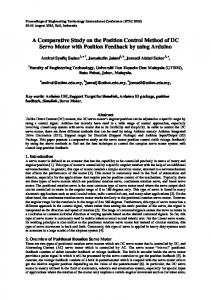
q1 ; deflection of the tip, q2 ; slope of the tip, τ ; applied torque; u=τ , θ ; angular position of the hub unit and elements of the matrices are functions of the length of link, the Young’s modulus of the link material, moment of inertia of the link, mass of link and added mass of link. Assumptions; a flexible beam of mass density ρ, crosssectional area A, Young's modulus E, length L, and crosssectional area moment of inertia IZ, rotates by arbitrary amount and at arbitrary rate in the vertical plane under the action of gravity. The beam is assumed to have small elastic deformations measured by q1, q2. A mass m is being on the free end of the beam. The beam is subjected to an external torque, τ , at its base, which is assumed to be rigidly attached to a rotating reference frame, as shown Fig. 1. In the derivation of the model, it is also assumed that all terms containing second-order elastic deformation terms of the form qi qj are much smaller than other terms and terms. m q1 q2
Z
g ξ
θ
τ
X
Figure 1. Schematic of flexible link arm
Dynamic equation of a single flexible link may be considered as n degree of freedom system and partitioned as the vectors q∈ Rl; θ ∈ Rm; τ ∈ Rm. Then, we may write the dynamics equations of the n degree of freedom system as ..
..
M1 q + M 2 θ + Kq + C + G = 0 ..
(3)
..
M 2T q + m33 θ + c3 + g3 = τ
(4)
M1 M ( q, θ ) = T M 2
(5)
where M2 m33
(5) is the symmetric, positive definite inertia matrix. K is . .
the stiffness matrix and K∈ Rl , C( q,θ ) contains Coriolis and centrifugal terms, G(q,θ) contains gravitational terms,
and τ ∈ Rm represents the input generalized force produced by hub unit for flexible link arm. III. PARTIAL FEEDBACK LINEARIZATION (PFL) Fully actuated robot manipulators are feedback linearizable by non-linear feedback. FLA has actuated and unactuated degrees of freedom and portion of the dynamics corresponding to the actuated degrees of freedom may be linearized by non-linear feedback. The remaining portion of the dynamics is non-linear and represents internal dynamics [2]. In this study, partial feedback linearization method is applied on a flexible link arm. Formulation of the collocated partial feedback linearization method is implemented as in [2]. A. Collocated Linearization We consider the following collocated output equation; y2=θ ∈Rm Consider the first equation of system dynamics (3) as ..
..
M 1 q + M 2 θ + Kq + F = 0
(6)
The equation can be rewritten using definition F=C+G for simplicity. M1 is an invertible matrix of dimension lxl (q∈ Rl) as a consequence of the system inertia matrix ..
M in (5). Therefore, we can solve for q in (7) as ..
..
q = − M 1−1 ( M 2 θ + Kq + F ) Substituting (6) into (4) and obtained; – .. – – M θ+ K+ F =τ – – – where the terms M , K , F are given by
(7) (8)
–
M = m33 − M 2T M1−1M 2 –
K= –
A feedback-linearizing controller can be defined for (6) according to – – – τ = M v2 + K + F (9) v2∈ Rm is an additional control input. The complete system up to this point may be written as
..
θ = v2 y2 = θ
V2
_
–
PD
M(
FLA –
(10)
..
M 1 q + Kq + F = −M 2 v2
.
(14)
..
θ = v2 (15) The system given in (3)-(4), is equivalent to the system (14)-(15) and is said to be Strongly inertially Coupled (SIC) if and only if Rank(M2(q,θ))=l (16) n for all configuration variables in R space. Inspecting the dynamic equations, rank M2=2, which is equal to passive degrees of freedom of the single link flexible system. According to the requirement of SIC, v2 can be used as a control input to control the response of θ. From equation (14), v2 can be computed as (17)
Since the definition of M2 is column matrix, it can be computed as a left pseudo-inverse M 2† for M2 according to M 2† = ( M 2T M 2 )−1 M 2T
(18)
and v2 can be rewritten with additional control input v1 (v1∈ Rl ) as v2 = − M 2† ( M 1v1 + Kq + F )
θ = − M 2† ( M1v1 + Kq + F )
(13)
.
B. Noncollocated Linearization In this section, the non-collocated linearization method is applied to the system. Linearization is realized according to passive configuration variables of the system by non-linear feedback. In this case, q1 and q2 are passive degrees of freedom. To apply non-collocated partial feedback linearization method, the system equations (10)-(11) can be rewritten,
It can be seen that the system from v2 to y2 is linear and of second order. The equation (10) represents the internal dynamics of the flexible link arm. If y2d = θ d represents a desired set-point for the active configuration variable (θ ), then the additional control term v2 may be chosen as,
−
Figure 2 : Block diagram of the proposed control method
System dynamic equations become
.
q, θ
K (q ) + F (q, q, θ , θ )
(11) (12)
v 2 = K P (θ d −θ ) + K D θ
. .
τ + +
..
F = f 3 − M 2T M1−1F
..
q θ
θd +
v2 = − M 2−1 ( M 1 q + Kq + F )
− M 2T M1−1Kq
M 1 q + Kq + F = −M 2 v2
where KP and KD are positive gains.
..
q = v1 ..
(19)
(20) (21)
(20)and(21) linearize the system according to the passive degrees of freedom, q. (20) represents the motion of the active degree of freedom which is the hub for a single flexible link arm and internal dynamics of the system relative to an output equation y1=q. The actual control input τ is given by combining (9) and (19). After some
algebraic manipulations, the controller can be found as below.
feedback-linearizing
–
–
–
τ = − M M 2† (M1v1 + Kq + F ) + K + F
(22)
Next we design the additional controllers for the passive DOF as PD form, by taking q1d = q2d =0. C. Switching Control Design In this study, the switching control is applied to achieving stability and improving vibration control performance of the flexible-link arm. For this case, the controller consists of a collocated or noncollocated nonlinear PFL functions and a supervisor, the supervisor is based on hub’s angular position setting time. Up to the desired angle of rotation in the given time, collocated PFL control algorithm is applied and then switching manipulation selects a noncollocated PFL control algorithm applied to control the system. We design the switching logic as; if if
t < thub’s set
– – – => τ = M v2 + K + F –
t > thub’s set => τ = − M
– – M 2† (M1v1 + Kq + F ) + K + F
The initial hub unit angular position of flexible link is chosen as θ=0, and shape modes are q1=0, q2=0. A position reference of θd = π 2 is applied, while q1d = q2d = 0, to make the vibrations go to zero as soon as possible. The collocated partial feedback linearization algorithm is applied to the system to reach the set desired position. At thub’s set = 3 sec., when the hub unit is assumed to have reached the desired position, the algorithm is switched to noncollocated partial feedback linearization with a control input. Proposed method is shown as a block diagram in Fig. 3.
θd
−
−
−
.
.
M (q )v2 + K ( q) + F ( q, q,θ ,θ )
•
Improved set-point position control is applied using a switching strategy to decrease vibrations and increase the positioning precision.
Top position that is the unstable equilibrium point of the flexible-link arm with payload is chosen as a set point and the results are obtained using step type reference. TABLE I. PARAMETERS OF THE SIMULATED FLEXIBLE LINK ARM Load mass (kg) Gravity (m/s2) Length of beam (m) Output diameter of beam (m) Input diameter of beam (m) Density of steel beam (kg/m3) Elasticity ( N/m2)
M G L
0.1 9.81 1
do
0.03
di
0.025
ρ
7850
E
2.07x10¹¹
A. Tip Position Control For this case, initial position of flexible link is chosen as θ=0, and shape modes are q1=0, q2=0. Desired position should be θ=π/2(unstable top position) and shape modes, q1 and q2, go to zero as soon as possible. When the system is loaded with 0.1 kg payload. Control torque is applied determining proposed control method and Fig. 4 demonstrates control performance. Fig. 4 a, b, c, and d demonstrates the hub position, variations of q1, q2 and tip position.
τ FLA
q,θ
Collocated PFL Control
. .
q1d=0 q2d=0
q,θ –
–
–
− M M 2† (M1v1 + Kq + F ) + K + F
Non-collocated PFL Control
Figure 3: Block diagram of the proposed switching control method
IV. RESULTS In this section, the results are presented for the proposed control methods using system parameters given in Table 1 for the flexible-link arm under payload given in Fig. 1. The results are obtained for two cases involving the control of the flexible arm, • Set-point control according to end-point position of flexible-link arm is implemented to reach the desired end-point using collocated PFL algorithm.
Figure 4: a) hub position b) shape modes q1, and c) q2 variationsand d)tip position using collocated partial feedback linearization control method
Fig. 5 demonstrates the tip position error and control torque signal variations during the simulation.
Fig. 7 gives the enlarged version of the q1 and q2 variation results. Fig. 8 shows the tip position error and control signal variation for this approach during the simulation.
Figure 5: a) tip position error, b) applied control signal.
B. Improved Tip Position Control Switching control design is used for this case according to define switching logic. At thub’s set = 3 sec., when the hub unit is assumed to have reached the desired position, the algorithm is switched to noncollocated PFL with a suitable control input. Fig. 6 a, b, c, and d demonstrates the related with switching manipulation results. Inspecting the results in Fig. 6 especially b and c , the improvement made with the addition of the noncollocated PFL can be observed clearly.
Figure 7: Zoomed version of Fig. 6. b and c
Figure 8: a) tip position error, b) applied control signal.
Figure 6: Improved a) hub position b) shape modes q1, and c) q2 variationsand d)tip position using noncollocated partial feedback linearization method at 3sec.
V. CONCLUSION In this study, the partial feedback linearization control method has been applied to the set-point control of a single flexible-link arm for tip position. Good performance results have been obtained with the collocated partial feedback linearization control developed for tip positioning. The switching strategy taken in set-point tip position control to apply noncollocated PFL for the elimination of flexible modes, q1 and q2, after the desired hub position is reached, has proven to improve the performance. The obtained results demonstrate the fulfillment of the performance goals. Simulation results successfully demonstrate the effectiveness of the proposed method.
REFERENCES [1]
[2] [3] [4] [5] [6]
[7]
[8] [9] [10] [11] [12]
[13]
[14]
[15]
G. Eason, B. Noble, and I. N. Sneddon, “On certain integrals of Lipschitz-Hankel type involving products of Bessel functions,” Phil. Trans. Roy. Soc. London, vol. A247, pp. 529–551, April 1955. Spong, M.W.; “Partial Feedback Linearization of Underactuated Mechanical Systems” IROS’94, Munich, Germany, pp. 314-321, Sept. 1994. Spong, M.W.; “The swing up control problem for the Acrobot” Control Systems Magazine, IEEE, Volume 15, Issue 1, Feb. 1995 Page(s):49 – 55. Khorrami, F., Jain, S., Tzes, A., "Experimental results on adaptive nonlinear control and input pre-shaping for multi-link flexible manipulators," Automatica, Vol. 31, No. 1, pp. 83-97,1995. Yang J.H., Lian F.L. and Fu L. C. "Nonlinear adaptive control for flexible link manipulators", IEEE Trans. on Robotics and Automation, Vol:13, No:1, Feb.97. H. Yang, H. Krishnan and M.H. Ang, “Tip-trajectory tracking control of single link flexible robots via output redefinition,” in Proc. IEEE Int. Conf. Robotics and Automation, pp.1002-1107, 1999. M. Gökaºan, S. Bogosyan, A. Sabanovic,"A Sliding Mode Observer and for A Single Link Arm", Conference on Decision&Control, CDC'98, Tampa, Florida, USA, December, 1998, pp.3625-3626. P. A. Chudavarapu and M. W. Spong. “On noncollacated control of a single flexible link".IEEE Int. Conf. on Robotics and Automation, MN, April, 1996. R. Olfati-Saber, "Trajectory tracking for a flexible one-link robot using a nonlinear noncollacated output," IEEE, CDC 2000. R. O. Saber, “Nonlinear control of underactuated mechanical systems with application to robotics and aerospace vehicles,” PhD thesis, MIT, Feb. 2001. X. Chen and T. Fukuda, “Robust sliding mode tip position control for flexible arms,” IEEE Trans. Industrial Electronics, vol.48, no.6, pp. 1048-1056, Dec. 2001. Rokui, M.R.; Khorasani, K.; “Experimental results on discretetime nonlinear adaptive tracking control of a flexible-link manipulator” Systems, Man and Cybernetics, Part B, IEEE Transactions on Volume 30, Issue 1, Feb. 2000 Page(s):151 – 164. S. K. Tso, T. W. Yang, W. L. Xu and Z. Q. Sun “Vibration control for a flexible-link robot arm with deflection feedback” International Journal of Non-Linear Mechanics, Volume 38, Issue 1, January 2003, Pages 51-62. S. B. Choi and J. W. Cheon “Vibration control of a single-link flexible arm subjected to disturbances” Journal of Sound and Vibration, Volume 271, Issues 3-5, 6 April 2004, Pages 11471156. Tzyh-Jong Tarn; Yunying Wu; Ning Xi; Isidori, A.; “Force regulation and contact transition control” Control Systems Magazine, IEEE, Volume 16, Issue 1, Feb. 1996 Page(s):32 – 40.
[16] Zairong Xi; Gang Feng; Jiang, Z.P.; Daizhan Cheng; “A switching algorithm for global exponential stabilization of uncertain chained systems”Automatic Control, IEEE Transactions on, Volume 48, Issue 10, Oct. 2003 Page(s):1793 – 1798. [17] Zhang, M.; Tarn, T.J.; “A switching control strategy for nonlinear dynamic systems”International Conference on Robotics & Automation, Proceeding of the 2003 IEEE Conference on Taiwan, September 14-19,2003. [18] Mingjun Zhang; Tzyh-Jong Tarn; “A hybrid switching control strategy for nonlinear and underactuated mechanical systems”Automatic Control, IEEE Transactions on Volume 48, Issue 10, Oct. 2003 Page(s):1777 – 1782.