TNT (Tracking Numerical Treatment) strength lies in online digital pulse processing. A present-day single FPGA is powerful enough to implement a digital.
265
TNT Digital Pulse Processor L. Arnold, R. Baumann, E. Chambit, M. Filliger, C. Fuchs, C. Kieber, D. Klein, P. Medina, C. Parisel, M. Richer, C . Santos, C. Weber 1 1
IReS - IN2P3, Strasbourg, France
Abstract – In order to perform a spectroscopy system, typical digital systems consisted of several DSP and a flash ADC. Nowadays FPGAs are well suited for this, since it is possible to implement various tasks running in parallel in a single FPGA device. Here we describe the practical implementation of preprocessing algorithms on a digital electronic module featuring one only FPGA for event processing. The overall system and its functionalities are presented, and then we report some results and future developments.
I.
micro controller (FX2, from Cypress [3]) is responsible for data readout and slow control.
INTRODUCTION
The main requirements of current data acquisition systems in nuclear physics are reasonable dead-time even at high counting rates, as well as good energy and time resolution for low and high energies. TNT (Tracking Numerical Treatment) strength lies in online digital pulse processing. A present-day single FPGA is powerful enough to implement a digital spectrometer, providing trigger and energy determination, as well as waveform capturing for subsequent analysis. The parallel processing capabilities of FPGAs enables a higher throughput and further reduces the event processing time, thanks to large amount of on-chip memory and dedicated multipliers. TNT main modules are NIM-based cards providing digital spectrometry and waveform acquisition from up to four input signals from detector's preamplifier. They are controlled through an USB bus by an user-friendly acquisition software. II.
OVERVIEW
The first generation of TNT (referred as TNT1) provided 65MHz, 14-bits sampling capabilities for two channels. The TNT1 is primarily designed to be used as a test bench for the implementation of digital signal processing algorithms. Current TNT (TNT2) is built upon TNT1. It features four acquisition channels operating in parallel and offers a better high-resolution spectroscopy. Each channel combines a fourth order anti-aliasing Nyquist filter (cut-off frequency of 40 MHz), higher sampling speed (100MHz) and 14-bits resolution data bus by using the AD6645 Flash Analog to Digital Converter (FADC) from Analog Devices [1]. On-board processing provides real time operation and high throughput. A Xilinx Virtex II FPGA [2] implements pulse processing and hardware control. An additional Spartan II FPGA provides system reconfiguration. There is the possibility to add new features by downloading the bit stream to the main FPGA via the USB bus. An 8051 compatible
0-7803-9183-7/05/$20.00 ©2005 IEEE.
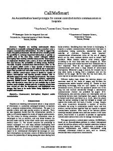
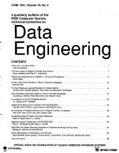
Fig. 1. TUC, graphical user interface to TNT.
The acquisition software, TUC, is in charge of slow control and monitoring of the boards in addition to providing tools for data visualization and saving. Spying of the data and counting rate is possible thanks to its graphical user interface. In addition, TUC allows the reconfiguration of the embedded functionalities running on the FPGAs. Written in java, it can run on many different operative systems. Data readout is performed by the computer through a 16 bits, 48MHz universal serial bus (USB) interface with an observed maximum transfer rate of 30Mbytes/s. It can manage a variable number of TNT modules, assisting the user in changing settings. Finally, it should be noted that the communication protocol between TNT modules and TUC is open and hence, it can be managed from any software. III.
DSP ALGORITHMS
A. Deconvolution Digitization of the preamplifier output signals allows trapezoidal shaping [4], [5], replacing traditional analog Gaussian shaping. This provides a good compromise between counting rate and resolution. In addition, it offers high-energy resolution, reduces ballistic deficit, and provides excellent
266
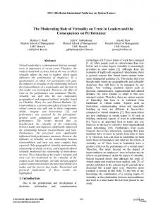
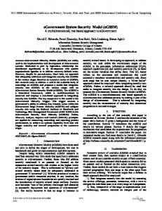
Fig. 2 Oscilloscope capture where the signal from the preamplifier, along with its deconvoluted version, can be appreciated.
A coincidence / veto time window can be defined to accept only events with a certain hit pattern. Different delayed, variable length time-windows of up to 650μs are accepted. Several general-purpose I/O NIM interfaces are available for this. Finally, an extern event can be used to resynchronize all time stamp counters by referring them to a common reference. This is also useful to synchronise with other systems. IV.
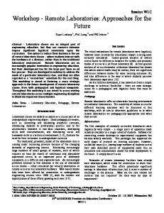
B. Trigger Low energy threshold is attainable thanks to dedicated triggering schemes, specially designed for a digital, real time hardware implementation [7], [8]. The first sub module, a delay-subtract unit (DS), differentiates the digitized preamplifier signal to remove any offset. The resulting signal is then fed onto a moving average (MA) unit, which acts as a low pass filter, removing noise. Finally, the signal is compared to a threshold value (leading edge trigger). Delays from the DS units can be adjusted up to 320 ns. by using SRL16 shift registers, an optimized Virtex II resource. In order to prevent false trigger from signal glitches, the trigger signal has to achieve a minimum width and therefore the trigger filter has to exceed the threshold for a minimum time. The design is shown in figure 3.
The working mode of TNT is the following: each channel accepts signals directly from a detector preamplifier. After an offset stage, signals are digitized in order to apply real time digital processing. Triggering, pile-up inspection and filtering of the data stream is performed by the FPGA, as well as averaging and detection of peak amplitude (Fig. 4). Every time a pulse is detected, parallel signal processing executes and outputs event data. The data is then transmitted over the USB interface to the user’s computer, which acts as an event collector and increments a 32k MCA spectrum for each channel, generating a histogram. This operating mode offers the best bandwidth to data flow ratio.
DS FADC Signal
C. Clocking Several TNTs can run synchronously: all waveform digitizers, triggers and time stamps are driven by the same periodic signal in a daisy chain configuration. The LVDS port can be used for sending a common clock to the whole system, thanks to advanced clock management capabilities provided by the AD9852 Direct Digital Synthesis (DDS) device [1]. It provides a stable, low jitter, high frequency resolution clock signal to fed the FADCs in order to obtain the best possible signal to noise ratio (SNR).
OPERATING MODES
DS
ACC
>
& Z-n
MA Threshold Fig. 3. Trigger scheme.
Trigger
baseline stability at high counting rates. The trapezoidal shaping eliminates the rise time effects due to the adjustable flat top period. Finally, it can be conceived in a recursive way, which means that any output sample can be obtained from the previous one plus a limited number of input samples. This form is well suited for an on line implementation on dedicated hardware [6]. TNT benefits from FPGAs ability to perform several tasks in parallel. The FADC output is processed continuously using a pipelined, fast architecture to generate a real time shaped pulse, as shown in figure 2. A wide range of filter parameters is provided for accurate set-up and greater flexibility. The rise time and flat top width adjustments have both been expanded (up to ~10 μs.) to finetune spectrometer performance. Peaking time goes from 100 ns to about 20 μs, with adjustable flat top duration. Pole/zero cancellation performs automatic fall time detection and correction. Baseline restoration (BLR) is carried out through an exponential average of the baseline, authorizing its minute adjustment for applications requiring wide dynamic rate counting. BLR allows a proper suppression of the pedestal of the energy filter. It also improves the energy resolution considerably by suppressing the negative influence of detector leakage currents on base line stability. The output of the pulse shaper and other test signals are routed to a 12 bits, 100 MHz. Digital to Analog Converter (DAC) for diagnostic purposes.
267
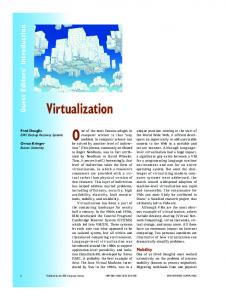
D. Oscilloscope mode TNT2 module can continuously acquire waveforms with 14-bit precision, which are sent into the digital pulse shaper. This data flow is also stored into a circular buffer, implemented as an extern memory to the FPGA. This First Input First Output (FIFO) has a depth of 1024K entries corresponding to 10.4 ms. worth of event waveform data, at sampling intervals of 10 ns. When an event trigger has been received, the module can incorporate waveforms of arbitrary length into its output data stream for offline analysis. As in a digital oscilloscope, it is possible to record pre-trigger waveform data. E. Processing mode With the aim of improving energy resolution, customized hardware in the FPGA determines the average value at the flat top of the shaped pulse. As shown in figure 4, this average can be calculated using an arbitrary number of samples. This more general strategy is intended for further noise filtering, and includes the particular case of a single sample. The readout takes place over the USB using a low level block transfer protocol. This implies some buffering in order to avoid data loss due to non continuous data readout. The flexibility of TNT modules lies in the FPGA, which provides fully dual-port embedded memory blocks for critical signal processing applications [2]. It is used as FIFO data buffers here, with independent management of the read and write pointers and fully synchronous and independent clock domains for the read and write ports. Count vectors provide visibility into the number of data currently in the FIFO. Figure 5 shows how this flag can be useful for inspection of possible data loss depending on the counting rate.
Fig. 5. FIFO filling flag: when this flag saturates, no event readout is possible. Some data loss can be appreciated in the figure. Slope is dependent on counting rate.
Information from previously analyzed pulses is stored in these FIFOs while continuing to process the data flow. No dead time will be present at this stage, since no storage and further treatment of the data flow is necessary for event generation. The depth and length of the data buffers can be configured according to the required information, up to the FPGA's full memory capacity. Buffers are continuously filled with energy value, time of trigger occurrence (48-bit time stamp) and event counter on an event-by-event basis, which allows an offline inspection of the number of events rejected. This configuration allows a maximum depth of 16Kbits. In parallel, this information is read out from the FIFO at up to 30 Mbytes/s. Finally, waveform capture and energy processing modes may run independently or in parallel. This provides offline pulse shape analysis of the full trace, along with derived results. Thus, position location and particle discrimination can be studied. V.
RESULTS
In order to study the capabilities of the digital system, the energy resolution of a small planar Germanium detector was investigated. We compare here TNT with the performances of a classical spectroscopy array. Conventional analog NIM electronics results are 0.7keV FWHM for the 60keV 241Am peak and 2.23keV FWHM for the 1.33MeV 60Co peak with a 4.8μs of peaking time. At 9.6μs of peaking time, we measured 0.6keV FWHM for the 60keV 241Am peak and 1.87keV FWHM for the 1.33MeV 60Co peak. The count rate was 4kHz. Fig. 4. Pile-up rejection and energy averaging on the flat top. A trigger detects energy deposition, but the event is rejected when the measure is influenced by a new event.
268
TABLE 1. Counting Rate Dead Time (% Trapezoidal FWHM [keV] FWHM [keV] (kcps) of rejection) Peaking Time @ 60 keV @ 1.33 MeV (241Am) (60Co) 5
0,1
2.20 Ps
0.61
1.81
25
0,6
2.20 Ps
1.01
1.96
52
1
2.20 Ps
1.02
1.98
95
2,5
2.20 Ps
1.23
2.03
Table 1 summarizes performances with digital electronics. The test shows acceptable results both in term of energy resolution and dead-time even at high counting rates. No data loss due to the USB is appreciated at the higher counting rate, and all event rejection is due to pile up. The energy resolution at high count rates is mainly limited by the detector. The dependence of the energy resolution on the trapezoidal filter parameters was measured and the best energy resolution was obtained. At low energies the SNR decreases, becoming the contribution of noise from the electronics more important. This makes the resolution very sensitive to sampling inaccuracies, as differential non linearity (DNL). Promising results [7] on DNL correction should be considered in further tests. TNT1 has been successfully used by the GRACE group of IReS for several months: the aim was to measure (n, xn) reaction cross-section induced by a neutron beam at GELINA (IRMM Geel) [6]. The first concern was the separation time between the gamma flash and the fastest neutrons which is not larger than 2.5μs. The second one was the beam frequency (800Hz). So on one hand, one needs a fast way to compute the energy within the 2.5μs time scale and on the other hand, one needs to overcome the acquisition dead time coming with the data readout in case of offline analysis. TNT's digital, shorter pulse shaping time offers higher count rates, and online treatment of the energies lowers the bandwidth. Our system has been tested in the measurement of the 207Pb(n,2n) reaction. For a 100% coaxial HPGe detector, the energy resolution on the 803keV transition in 206Pb is equal to 2.6keV, with a 3μs dead time which allows recording events corresponding to neutron energies up to 14MeV, or to 3.9 keV with a 2.5 μs allowing the measurement of neutrons up to 20 MeV. The digital electronics bring a unique opportunity to perform spectroscopy of very heavy elements, where the productions cross section is less than a few 10 nb., with a high fission cross section. TNT2 cards are foreseen to be used in 2 complementary projects: GABRIELLA at JINR DUBNA and JUROGAM II at JYFL Jyväskylä [9]. For the latter project, the TNT cards will be linked to the existing TDR acquisition system where each detector's information is associated to a timestamp given by a 100MHz clock (METRONOME). Some test regarding time alignment
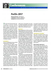
between the TNT cards and the TDR system have been successfully run recently at JYFL to assess its compatibility with current installation. The Compton suppression has also been tested with sources (Fig. 6) and with beam 36Ar on a 107,109Ag target up to a 100 kHz rate per TNT channel. Analysis of the corresponding data is under progress.
Fig. 6. Compton suppression at JYFL Jyväskylä.
Finally, the low noise of the analog stage, as well as the good performances in terms of SNR measures within the TNT2 makes it a reference design for the digitizer part of the AGATA [10] collaboration. VI.
FUTURE DEVELOPMENTS
In order to improve the TNT system's performances, an event collector and synchronization module is currently under development. It will distribute a common clock and time stamp reference through a 2 gigabits serial link, as well as some global commands, such as start acquisition and reset settings. The acquisition software TUC will be improved and dispatched over the network allowing remote slow-control and monitoring. This will improve the whole system throughput since less computation will be done on the computers actually connected to the cards. This is in prevision of the use of more than 40 channels for experiments with very high counting rates in Jyväskylä and Dubna sites. ACKNOWLEDGMENT We would like to thank the Grace group of IReS, especially Dr. Gerard Rudolf and Dr. Strahinja Lukic for their helpful contributions in the development of algorithms. Tests for the future Jyväskylä experiments were performed with the help of Dr. Benoit Gall. Our final thanks go to Dr. Gilbert Duchêne for useful discussions and his support to this project.
269
REFERENCES [1] [2] [3] [4]
www.analog.com www.xilinx.com www.cypress.com Valentin T. Jordanov and Glenn F. Knoll, "Digital synthesis of pulse shapes in real time for high resolution radiation spectroscopy", Nucl. Instr. Meth. A345 (1994), 337-345 [5] A. Georgiev and W. Gast, "Digital pulse processing in high resolution, high throughput, gamma-ray spectroscopy", IEEE Trans. Nucl. Sci. Vol. NS-40 (1993) 770-779 [6] Strahinja Lukic, "Mesure de sections efficaces de réactions (n,xn) par spectroscopie J�prompte auprès d'un faisceau à très haut flux instantané", PhD thesis, Strasbourg, 2004 [7] Martin Lauer, "Digital Signal Processing for segmented HPGe detectors. Preprocessing Algorithms and Pulse Shape Analysis", PhD thesis, Heidelberg, 2004 [8] Lucian Mihailescu, "Principles and methods for A J�ray tracking with large volume germanium detectors", PhD thesis, Bonn, 2000 [9] http://www.phys.jyu.fi/research/gamma/jurogam/index.html [10] The Advanced Gamma-Tracking array AGATA, http://wwww2k.gsi.de/agata/