that subcircuits N3 and N4 of Figure 1 share internal gates. Then when ... traditional logic synthesis, the focus in this paper is on optimization of .... LS_TE answers the question above. Let N be ...... the full power of TEP is exhibited for multi-output circuits. ... Berkeley, Electronics research laboratory, May 1992. [9] E.M. ...
Toggle Equivalence Preserving (TEP) Logic Optimization Eugene Goldberg (Cadence Berkeley Labs), Kanupriya Gulati and Sunil Khatri (Texas A&M University)
ABSTRACT We describe a procedure (called the TEP procedure) that, given a multi-output circuit M, builds another multi-output circuit M* that is toggle equivalent to M. The TEP procedure can be used in the following two scenarios. First, since for single-output circuits toggle equivalence means functional equivalence, the TEP procedure can be used in “regular” logic synthesis. Second, the TEP procedure enables a powerful synthesis method called LS_TE (Logic Synthesis preserving Toggle Equivalence). Given a circuit N and its partitioning into subcircuits Ni , LS_TE builds an optimized circuit N* by replacing subcircuits Ni with their toggle equivalent counterparts N*i . The replacement of Ni with N*i is done by the TEP procedure. We give results of optimizing single-output circuits by the TEP procedure and some preliminary results of using the TEP procedure in LS_TE. These results show the promise of the TEP procedure and LS_TE.
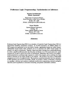
1. INTRODUCTION In [4], a new method of logic synthesis was introduced. We refer to this method as LS_TE, which stands for Logic Synthesis preserving Toggle Equivalence. As shown in Figure 1, assume that a partitioning of N into subcircuits Ni, i=1, 2,…, k is specified. The main idea of LS_TE is to optimize N by replacing each subcircuit Ni with a toggle equivalent counterpart N*i, i=1,2,..,k. Let us consider how LS_TE works by the example of Figure 1 where circuit N is partitioned into four subcircuits N1,..,N4. First, subcircuits N1 and N2 are replaced with their toggle equivalent counterparts N*1 and N*2. Then the relations CF(N1, N*1) and CF(N2, N*2) betweens outputs of N1 and N*1 and N2 and N*2 are computed. (These relations are called correlation functions (CF)). Then a single-output subcircuit N*3 that is toggle equivalent to the single-output subcircuit N3 under the constraints specified by CF(N1, N*1) and CF(N2, N*2) is built. Since toggle equivalence for single output circuits means functional equivalence (modulo complement), outputs y1 and y*1 are functionally equivalent (modulo complement). Finally single-output subcircuit N4 is replaced with a single-output toggle equivalent subcircuit N*4, which makes outputs y2 and y*2 functionally equivalent (modulo complement). So the optimized circuit N* consisting of subcircuits N*1,..,N*4 is functionally equivalent to N modulo complement of its outputs. The advantage of LS_TE is twofold (at least). First, LS_TE is scalable. The complexity of LS_TE is linear in the
number of subcircuits Ni and exponential in the size of the largest subcircuit Ni or N*i,i=1,..,k. Since the number of subcircuits toggle equivalent to Ni is huge even if Ni is very small, LS_TE can explore a very large search space and still have linear complexity. Second, LS_TE can escape local minima that would trap a solution obtained by a traditional logic synthesis procedure (Section 3). y1 N3
y2
y*1
N4
N
N*
N1
N2
N*i is obtained from N i by TEP
N*1
N*3
y*2 N*4
N*2
Figure 1. Optimization of circuit N by LS_TE
Unfortunately, [4] did not provide a specific procedure that, given a subcircuit Ni, would build a toggle equivalent subcircuit N*i. The main contribution of this paper is the introduction of such a procedure which we refer to as the Toggle Equivalence Preserving (TEP) logic optimization procedure. In the TEP procedure, we use a non-trivial convergence scheme that makes this procedure structureagnostic. That is if a circuit M′ toggle equivalent to an original circuit M is built by the TEP procedure, the topology of M′ is not limited to that of M. This important feature of TEP is discussed in Section 3. In the formulation of LS_TE given in [4], circuit N to be optimized is partitioned into subcircuits Ni, i=1,..,k However, LS_TE can be also applied if, for example, subcircuits Ni share internal gates. Suppose, for instance, that subcircuits N3 and N4 of Figure 1 share internal gates. Then when building subcircuit N*4 toggle equivalent to N4, one can reuse the logic of N*3 (assuming that N*3 was synthesized before N*4). Such logic sharing can be done by the TEP procedure (slightly modified). However, a discussion of this topic is beyond the scope of this paper. As we mentioned above, for single-output Boolean functions, toggle equivalence is the same as functional equivalence modulo negation. So, besides enabling LS_TE, the TEP procedure can be used in traditional logic synthesis. In order to compare the TEP procedure with traditional logic synthesis, the focus in this paper is on optimization of single-output functions. Even though the vast optimization flexibility of the TEP procedure can not be invoked for single-output functions, it still has the
advantage of being structure-agnostic. As a consequence, for many single-output circuits the TEP procedure found better solutions than SIS [9]. Our initial results also show that for multiple output circuits (where the vast optimization flexibility can be exploited), the LS_TE procedure gave significant improvements over SIS The rest of this paper is organized as follows. Section 2 discusses related previous work, including a comparison and contrasting of LS_TE and TEP with SPFDs [1][10][12]. In Section 3, we emphasize some important features of LS_TE and TEP procedures. Section 4 provides definitions. Section 5 details our TEP procedure. In Section 6, we report results of our experiments. Section 7 concludes the paper, with some directions for future work in this topic.
2. PREVIOUS WORK Multi-level logic synthesis can be performed using algebraic means such as factorization [2], kernelling [2][11] etc. Although these techniques are fast, being algebraic, they explore only a limited portion of the optimization space. Other techniques like ODC [6][7] and CODC [8] perform don't care based optimization, but they do not modify the structure of the circuit. (Sometimes a node gets removed as a result of don't care based optimization. However, such an occurrence is rare.) Toggle equivalence is different from the algebraic techniques, since it explores the ''Boolean'' options in the search space, while it differs from multi-level don't care based techniques since it does not restrict itself to the original circuit topology. Sets of Pairs of Functions to be Distinguished (SPFDs) were introduced in [1][10][12] as a new way to do logic optimization. One should distinguish between SPFDs as a means to express circuit flexibility and concrete methods for computing SPFDs. The main difference between LS_TE and the method for computing SPFDs of [10][12] is that LS_TE is scalable. The method for computing SPFDs of [10][12] is unscalable because SPFDs are built by computing non-local relations between points of the circuit. Besides, when computing SPFDs by the method of [10][12] one has to follow the circuit topology. On the other hand, computations in LS_TE are local because they involve only subcircuits Ni and N*i (and correlation functions relating their inputs). Besides, LS_TE preserves only the highlevel structure of the circuit (because subcircuits Ni and N*i are connected in the same way) but the topology of subcircuits Ni and N*i can be vastly different. The “language” of SPFDs is sufficient to express the notions of toggle implication and equivalence that we use in the paper. For example, to test that circuits M and M′ are toggle equivalent one can build SPFDs of M and M′ and check them for graph isomorphism. However, toggle
equivalence of M and M′ can be computed much more efficiently without building their SPFDs (by performing two SAT-checks). Moreover, the formulation of the TEP procedure in terms of SPFDs is hard at best. An SPFD is a relation between input assignments while the TEP procedure operates on output assignments and the same pair of output assignments (i.e. the same toggle) may be caused by an exponential number of pairs of input assignments. In a sense, the problem is that the definition of SPFDs was tailored to facilitate their computation from outputs to inputs, while in LS_TE and TEP procedure computations go in the opposite direction.
3. IMPORTANCE OF LS_TE AND TEP In this section, we emphasize two important features of LS_TE and the TEP procedure. In Subsection 3.1, we show that LS_TE, in terms of equivalent transformations, can make moves that increase the size of intermediate circuits. This allows LS_TE to escape local minima that would trap a solution built by a traditional method of logic synthesis. In Subsection 3.2 we discuss the importance of the novel convergence scheme of the TEP procedure.
3.1 Escaping local minima in LS_TE Given a circuit N, a typical synthesis transformation is to replace a multi-output subcircuit N′ of N with a functionally equivalent subcircuit N″ such that |N″ | < |N′ |. (Here |M| is the size of circuit M.) The size of N′ is kept small for complexity reasons. Suppose there is no transformation decreasing the size of N such that |N′ | < p. This means that circuit N is stuck in a local minimum. To escape this minimum, one needs to make equivalent transformations that affect subcircuits of N larger than p. But how does one make such transformations in a scalable manner? LS_TE answers the question above. Let N be partitioned into subcircuits N1,..,Nk. By replacing subcircuits Ni,i=1,.,k with toggle equivalent counterparts N*i LS_TE makes a single equivalent transformation that may encompass the entire circuit N (then the subcircuit N′ we replace with an equivalent one is N itself). If the size of subcircuits Ni is small, this transformation can be done efficiently. Note that LS_TE can optimize N even if |Ni| < p, i=1,.,k. The reason is that replacement of Ni with N*i is not an equivalent transformation. So LS_TE can get N out of a local minimum even by making transformations of “small scope”. Suppose N implements the expression x2 < 100 as shown in Figure 2. Here subcircuit N1 implements y=square(x) and subcircuit N2 implements y < 100. (Let assume that the number n of bits in x is small enough to be handled efficiently.) LS_TE can optimize N as follows. First N1 is replaced with an optimized subcircuit N*1 toggle equivalent to N1 (e.g. N*1 may implement the function abs(x) which is the simplest function toggle equivalent to square(x)). Then
output relation CF(N1,N*1) is computed (as described in [4]). After that a subcircuit N*2 toggle equivalent to N2 under constraint CF(N1, N*1) is built. (If N*1 implements y∗=abs(x), then N*2 implements y∗< 100 modulo negation.) Note that N can not be optimized much by replacing N1 with a functionally equivalent subcircuit N*1 (for example, N1 can be an optimal implementation of square(x)). At the same time, LS_TE can dramatically optimize N because it can replace N1 with a toggle equivalent subcircuit.
Figure 2. Optimization of expression x2 < 100 by LS_TE
The replacement of N1 with N*1 can be “simulated” as an equivalent transformation as shown in Figure 2 (on the right). Here R*1 is a re-encoding circuit such that N1 = R*1(N*1). (The second step of LS_TE is “simulated” as replacing N*1 and R*1 with N*2.) Note that even though N*1 is much smaller than N1 it may be the case that |N1| < |N*1|+ |R*1|. In other words, the reason why LS_TE can escape local minima is that it may make transformations that temporarily increase the circuit size. (A discussion of this topic can be found in [5].)
3.2 Novel convergence scheme of the TEP procedure As mentioned above, the importance of the TEP procedure is due to its enabling LS_TE. However, the TEP procedure is also important in its own right. Given a singleoutput circuit N, the TEP procedure can build a functionally equivalent circuit N* with a completely different topology. (So it can be used in “regular” logic synthesis without any relation to LS_TE.) This property is extremely important for at least three reasons. First, N may not have any topology to reuse (e.g. if N is specified as the truth table or is represented implicitly). Second, N may contain some non-local redundancy which makes unreasonable to reuse its. Third, one may need to implement N using a particular library of gates (e.g. in technology mapping) and the current topology of N may be not good for these library. In the current synthesis methods, if the topology of N can not be reused for some reason, a new circuit N* is obtained from a very limited space of implementations (N* may be further optimized using local transformations). For example, in SIS [9], if N is represented as the truth table, first, a circuit N* equivalent to N is synthesized as a sum-ofproducts (which is a very limited class of circuits). Then by
local transformations a multi-level circuit is obtained from N*. Another approach would be to build a circuit N* of multiplexers (i.e. build a BDD [3]) equivalent to N and then optimize it using some local transformations. BDDs is another example of a restricted class of circuits. The reason why current methods have to restrict the class of implementations considered when changing the topology of N is the “convergence problem”. Suppose we build a circuit N* that does not use the topology of N. Then we have to make sure that the network of gates being built “converges” to a circuit equivalent to N. The TEP procedure solves this problem by introducing a very simple and general convergence scheme. Namely, it builds a sequence of circuits N 1, N 2,… such that a) N i+1 toggles strictly less than N i and b) every circuit of this sequence toggles at least as much at the original circuit N. Here N 1 is an “empty circuit” consisting only of inputs of N. In other words, the TEP procedure builds a sequence of circuits that monotonically lose toggles until a circuit N m toggle equivalent to N is built. The TEP procedure also restricts the class of implementations it considers since it requires that only primary outputs of N i are allowed to feed the gates of N i+1 that are not in N i. However, this is a mild restriction in comparison to ones used by existing methods. So, the TEP procedure can select an optimized implementation from a very general class of multi-level circuits.
4. PRELIMINARIES AND TERMINOLOGY In this section, we recall the notion of toggle equivalence and its properties. All the propositions given in this paper are either proven in [4], or can be easily derived from them.
4.1 Toggle Equivalence of Boolean Functions
Definition 1. Let f:{0,1}n → {0,1}m be an m-output Boolean function. Then, given y′ = f(x′ ) and y″ = f(x″), the pair (y′, y″ ) is a toggle if y′ ≠ y″. Definition 2. Let f1 and f2 respectively be two m-output and k-output Boolean functions with the same set of variables. Functions f1 and f2 are called toggle equivalent if f1(x′′) ≠ f1 (x″″) ⇔ f2(x′′) ≠ f2(x″″). Circuits N1 and N2 implementing toggle equivalent functions f1 and f2 are called toggle equivalent circuits. Proposition 1. Let f1:{0,1}n → {0,1}m and f2 {0,1}n → {0,1}k be m-output and k-output Boolean functions of the same set of variables. Let f1 be f2 toggle equivalent. Then there is an invertible function H such that f1(x)=H(f2(x)) and f2(x)=H-1(f1(x)). Proposition 2. Let f1 and f2 be toggle equivalent single output Boolean functions. Then f1=f2 or f1=~f2. Definition 3. Let N be a circuit. Let Y be the set of all variables of N. Let Sat(N) be the CNF expression for N, such that Sat(N)=1 iff the assignment y to Y is consistent
within the circuit N. For example, if N consists of just one AND gate w = x1 ∧ x2, then SAT(N) = (~x1 ∨ ~x2 ∨ w)∧ (x1 ∨ ~w) ∧ (x2 ∨ ~w). Proposition 3. Let N1 and N2 be two toggle equivalent circuits, with variables Y1 and Y2 respectively. Let the output variables of N1 and N2 be Z1 and Z2 respectively. Then the function H*(Z1,Z2) specifying the one-to-one mapping H between the output vectors produced by N1 and N2 can be obtained from Sat(N1) ∧ Sat(N2) by existentially quantifying away the variables of (Y1 ∪ Y2)\ (Z1 ∪ Z2). (Then H*(z1, z2) =1 iff there is an input vector x such that N1(x)=z1 and N2(x)=z2.)
4.2 Implication of Toggling In this subsection, we introduce the notion of implication of toggling and describe how toggle equivalence and implication of toggling can be tested. Definition 4. Let f1: {0,1}n → {0,1}m and f1: {0,1}n → {0,1}k respectively be two m-output and k-output Boolean functions with the same set of input variables. Toggling of f1 implies toggling of f2 iff for any pair of input variable assignments x′ and x″, f1(x′′) ≠ f1 (x″″) f2(x′′) ≠ f2(x″″). Definition 5. Let f1 and f2 be multi-output Boolean functions. Toggling of f1 strictly implies toggling of f2 if toggling of f1 implies toggling of f2 and there is a pair of assignments x′ and x″ such that f1(x′′)=f1 (x″″) while f2(x′′) ≠ f2(x″″). We will denote by f1 ≤ f2 (respectively f1 < f2) the fact that toggling of function f1 implies toggling of (respectively strictly implies toggling of) f2. Let circuits N1 and N2 implement functions f1 and f2 respectively. We will denote by N1 ≤ N2 (respectively N1 < N2) the fact that f1 ≤ f2 (respectively f1 < f2). Proposition 4. Boolean functions f1 and f2 are toggle equivalent iff f1 ≤ f2 and f2≤ f1.
4.2.1 Testing for Implication of Toggling Let N1 and N2 be two Boolean circuits to be checked for implication of toggling. Let X be the set of input variables of N1 and N2, while Y1 and Y2 are respectively the sets of variables of N1 and N2. Let Z1 and Z2 be the sets of output variables of N1 and N2 respectively. Also, assume N*1 and N*2 are copies of N1 and N2, with output variables Y*1 and Y*2 respectively, and input variables X* . Then N1 ≤ N2 holds iff the function S(N1, N2) is unsatisfiable, where S(N1, N2) = SAT(N1) ∧ SAT(N2) ∧ SAT(N*1) ∧ SAT(N*2) ∧ (Y1 ≠ Y*1) ∧ (Y2 = Y*2). Based on this, we can make the following three comments. 1) To test if N1 ≤ N2, we simply test the satisfiability of S(N1, N2). If it is unsatisfiable (i.e. a constant zero), we conclude that N1 ≤ N2. 2) If S(N1, N2) is satisfiable, it means that there exists a pair of input vectors x and x* for which circuit N1 toggles, while N2 does not. 3) Let S(N1, N2)
be satisfiable. If we removed all toggles from N1 that “are not in” N2, we would have N1 ≤ N2. In other words, given two circuits N1 and N2, we can define a function find_toggle_setdifference(N1, N2) = ALLSAT(S(N1, N2)) which returns toggles of N1 that are not matched by toggles of N2. This is the set of toggles that must be removed from N1. If the resulting set ALLSAT(N1, N2) is too large, its manageable subset can be used. From Proposition 4, it follows that checking for toggle equivalence reduces to two satisfiability checks (henceforth called SAT checks).
4.3 Correlation function In this section, we briefly introduce the notion of correlation function, to extend definitions of toggle implication and toggle equivalence to the case when functions f1 and f2 have different sets of input variables. Definition 6. Let X and Y be two disjoint sets of Boolean variables (the number of variables in X and Y may be different). A function CF(X, Y) is called a correlation function if there are subsets SX ⊆ {0,1}||X| and SY ⊆ {0,1}||Y| such that CF(X, Y) specifies a bijective mapping M: SX → SY. Namely, CF(x, y)=1 iff x ∈ SX, y ∈ SY and y = M(x). Definition 7. Let Boolean functions f1 and f2 have different sets of variables (X and Y respectively) that are related by a correlation function CF(X, Y). f1 and f2 are said to be toggle equivalent under input constraint CF(X1,Y), if for any pairs (x, y) and (x′, y′) of input vectors such that CF(x, y)= CF(x′, y′ )=1, it is true that f1(x) ≠ f1(x′ ) ⇔ f2(y) ≠ f2(y′′). (Definition of toggle implication can be reformulated in a similar manner). In LS_TE, the output relation between toggle equivalent subcircuits N i and N*i is computed by existentially quantifying from SAT(Ni) ∧ SAT(N*i) ∧ * Constr(inp_vars(Ni),inp_vars(N i)) all but output variables of N i and N*i [4]. If Ni and N*i are subcircuits of the first topological level (and so have identical sets of input variables), then Constr(inp_vars(Ni), inp_vars(N*i)) just describes equivalence of corresponding variables. Since toggle equivalence of Ni and N*i means one-to-one mapping between output assignments, their output relation is a correlation function. In general, Constr(inp_vars(Ni), inp_vars(N*i)) is the conjunction of correlation functions that are output relations of all the subcircuits Nj, N*j feeding Ni, N*i. For the sake of simplicity, in Section 5, when describing the TEP procedure, we assume that circuit N1 and its toggle equivalent counterpart N2 have identical sets of variables.
5. TEP LOGIC OPTIMIZATION The TEP procedure produces the circuit N2 (given a combinational circuit N1) in a topological manner from inputs to outputs. These operations are illustrated in Figure 1 3. The circuit N2 is built up as a sequence of circuits N2 , m i 2 N2 , …, N2 . Each circuit N2 specifies a cut Ci of N2 consisting of the primary outputs of N2i. In this way, the sequence of cuts Ci that are produced, are topologically ordered. This means that for a pair of cuts Ci and Cp such that i < p no path from a primary input to a primary output of N2 can traverse Cp before Ci, although Ci and Cp may have common nodes. Then, if a node in Cp toggles for a given pair of input vectors, then there must be at least one node in Ci that toggles as well. So just from the fact that Ci and Cp are topologically ordered it follows that N2p ≤ N2i. N2
….
…. ….
N1
N2
N 23
C3 C2 C1 ….
N 2m
N 22 ….
N 21
Figure 3. Sequence of circuits N2i constructed by TEP
The TEP procedure starts with N21 = ∅ i.e. with an empty circuit which allows all possible toggles. As a result, N1 ≤ N21 (which is trivially true since the set of inputs forms a cut of N1). At each successive step, N2i+1 is created from N2i such that N2i+1 < N2i. The invariant that the TEP procedure maintains at each step is N1 ≤ N2i+1 < N2i. In other words, the TEP procedure selectively removes one or more toggles in each step, until it is true that N2m ≤ N1. At this step, since N1 ≤ N2m, N2m is toggle equivalent to N1, and the procedure returns the circuit N2m. TEP(N1) {if (is_constant(N1)) return “constant” ; N2current = ∅; while(true) {if (N2current ≤ N1) return N2current ; N2current = discard_toggles(N2current, N1); N2current = remove_redundant_outputs(N2current); }}
Figure 4. Pseudocode of the TEP procedure It is not hard to see that the TEP procedure has the desirable property of convergence. Since N21 has all toggles, and N2i+1 < N2i, the sequence of circuits N21, N22,…, N2m must converge to a circuit which is toggle equivalent to N1. The pseudocode of the TEP procedure is shown in Figure 4. To start with, we test if the input circuit N1 is a constant, in
which case the TEP procedure reports this fact. The sequence of circuits N2i mentioned earlier is built in the while loop. This sequence starts with an empty circuit N2current, which allows all possible toggles. In the while loop, we first check if N2current ≤ N1. If so, N2current is toggle equivalent with N1 (since N1 ≤ N2current by construction) and we return N2current as the resulting circuit N2. If N2current ≤ N1 does not hold, then a new circuit N2current is generated, such that it has at least one less toggle than the previous N2current . This operation is performed by the function discard_toggles, which is described in the next subsection. Finally, redundant outputs of N2current are removed in the function remove_redundant_outputs. An output of N2current is redundant if, after its removal from N2current, the condition N1 ≤ N2current still holds. Note that for each test for implication of toggling (i.e each “≤”check), we utilize the SAT-based algorithm described in subsection 4.2.1.
5.1 Discard toggles from N2i Figure 5 describes the pseudocode of the discard_toggles procedure used by the TEP procedure ( Figure 4). discard_toggles(N2current, N1) { R* = find_toggle_setdifference(N2current, N1); (N2temp, R) = remove_toggles(R*, N2current); D = find_toggle_setdifference(N1, N2temp); N2new_current = add_toggles(R, D, N2current, N2temp); return N2new_current ;} Figure 5. Pseudocode of the discard_toggles procedure The procedure discard_toggles consists of two parts. The procedures remove_toggles and add_toggles are explained in detail in the following subsections. In both these procedures, toggle removal and addition is done with AND gates, with their inputs appropriately complemented. The routine find_toggle_setdifference(N2current, N1) was sketched in subsection 4.2.1. The heuristics of remove_toggles and add_toggles are aimed at minimizing the size of N2.
5.1.1 Procedure remove_toggles The function remove_toggles adds an AND gate G to N2current, to remove at least one toggle in the set R*, which is computed in line 1 of the discard_toggles procedure. (R* specifies either the complete set of additional toggles that are present in N2current and are not required in N1 or a manageable subset of this set.) The resulting circuit is called N2temp, and the set of toggles of R* actually removed are referred to as R. Recall that each circuit N2i specifies a cut Ci of N2 (consisting of the primary outputs of N2i.) Suppose the circuit N2current specifies the cut Ccurrent. Then the AND gate G above may have as its inputs, any of the nodes on Ccurrent. After the addition of the AND gate G, the new cut Cnew is formed from Ccurrent by a) adding to Ccurrent the node
corresponding to the output of G; b) eliminating from Ccurrent the nodes that are toggling inputs of G. Suppose the cut Ccurrent consists of the set of nodes Y. Suppose that r = (y, y') is a toggle from the set R*. Let Y1 and Y2 form a partition of Y, such that Y1 (Y2) corresponds to the components of y and y' which are different (same). In other words, Y1 (Y2) corresponds to the nodes of Y that have different (same) values for the toggle r = (y, y'). To remove the toggle r, we add an AND gate G. We consider two cases. Case i): If Y1= 1, then gate G has two inputs. One of these inputs is specified by the variable of Y1, and another input is chosen from Y2. All possible polarities of the second input are considered as well. The configuration for which G(y) = G(y')=0 and that removes the largest number of toggles of R* is selected. Case ii): if Y1 > 1, then gate G has |Y1| inputs. These inputs are connected to the variables in Y1, with appropriate polarity selection to guarantee that G(y) = G(y') = 0. In both cases, the construction of gate G guarantees that G(y)=G(y')=0. After adding the gate G, we form the cut Cnew by removing from Ccurrent all the nodes in Y1 and adding the output of G. Then, the toggle r =(y, y') is removed from the nodes of Cnew. The circuit resulting from this operation is called N2temp.
re-introduced and p is the weight parameter (that was set to 1 in our experiments). We add only those gates for which n1 is 1 or more. Case ii): If |Y1| > 1 , then select the first input of H from Y1, and the second from Y, except the input already chosen as the first leg. The cost function to select inputs and their polarities is identical to the one explained in Case i above. After each AND gate added to the circuit, the set D is recomputed. The routine add_toggles continues to add AND gates until the set D reduces to ∅. At this point the resulting circuit N2new_current is returned. It satisfies the property that N1 ≤ N2new_current < N2current. Note that for a single gate added in remove_toggles, zero, one or more AND gates could be added in the following call of add_toggles.
6. EXPERIMENTAL RESULTS Our preliminary implementation of the TEP procedure is in SIS [9]. We performed various experiments to compare TEP with traditional logic synthesis commands. The experiments were performed on a 3 GHz Xeon CPU, with 2GB of memory. Table 1. Results for optimizing arithmetic expressions Exper.
collapse, #bits script.rugged time #gates script.rugged
TEP
BDD
time (s) #gates time(s) #gates time(s)
5.1.2 Procedure add_toggles Unfortunately, adding the gate G in the previous subsection may sometimes remove certain toggles that are required in N1. As a consequence, we have to perform a ''clean-up'' step, and add these toggles back into the design. We begin with computing D, the set of toggles that need to be added. D is computed by find_toggle_setdifference(N1, N2temp). The objective is to add minimum number of AND gates that re-introduce all toggles from D, and at the same time minimize the number of toggles that get re-introduced from R. It is not hard to prove that one can always reintroduce a toggle from the set D, by using a 2-input AND gate H, with appropriately selected inputs and input polarities, without re-introducing a toggle from the set R. The proof is omitted due to space constraints. Once again, we have two cases to consider, analogous to those in the previous subsection: Case i): When the gate G added by remove_toggles was a 2-input gate, with |Y1| = 1, then one of the inputs of H is the same as the node in Y1. The other input of H is selected from among nodes in Y2. All possible nodes and polarities are explored to maximize the weighted cost function n1+p∗n2. Here, n1 is the number of toggles of R prevented from being re-introduced, n2 is the number of toggles of D
x2 < C x2 < C x2 < C x2 < C x2 < C C1∗x < C2 C1∗x < C2 C1∗x < C2 C1∗x < C2
10 14 16 27 30 16 18 38 50
3 590 0.5 34 1,361 95 94 1,808 2,151 35 7,037 >10h 56 8,681 >10h 24 1,054 121 39 1,201 1,659 37 6,709 >10h 136 10,483 >10h
28 44 52 15 17 -
5 17 54 282 525 14 25 497 2,183
20 21 46 50 57 19 28 58 66
0.01 0.25 0.9 Mem Mem
0.07 0.11 Mem Mem
Table 1 provides the results of applying TEP procedure and SIS for optimizing circuits implementing the expressions x2 < C and C1∗x < C2 for different word sizes. (In contrast to the example of Subsection 3.1, the expressions above were optimized as one circuit i.e. by one call of the TEP procedure.) In all experiments, the value of C was chosen to be 200 (the results do not change much if one varies C). C1 and C2 were set to decimal value 11111. The two expressions above can be reduced to much simpler expressions x < C′ and x < C″ respectively where C′ is equal to sqrt(C) and C″ is equal to C2/C1. The objective of this experiment was to show that since TEP is structure-agnostic it can be used to simplify “non-local” redundancy. Note that although optimization of these expressions can be easily done manually, one can give examples of non-local redundancies that are much harder to find manually or by a program. Any logic synthesis procedure that changes the
original circuit's structure locally (like SPFDs or don't care based optimizations) can easily get trapped in a local minimum. Note that only for smaller values of C, C1 and C2, it is possible to build ROBDDs. For the experiments in Table 1, we set the threshold of R* at 10 as explained in sections 5.1 and 4.2.1 i.e. R* contained only 10 (out of a huge number of) toggles to be removed. The reason why the TEP procedure worked so well with such a small subset R* was that by adding an AND gate to remove a toggle of R* explicitly, we may implicitly remove a huge number of toggles that were “skipped” in R*.
delay for the output of script.rugged mapped by CT, while Columns 5 and 6 provide these numbers for the TEP output mapped by CT. The standard cell library had 38 gates, implemented in a 0.18µ process. The licensing agreement for CT requires us not to identify its name. The results of Table 2 indicate that TEP based circuits, after mapping, result in a 12.5% area improvement, and a 1.6% delay penalty over circuits optimized with script.rugged before mapping with CT. The TEP results improve on the script.rugged results for 85% of the examples in terms of area, and for 45% of the examples in terms of delay.
The first column in Table 1 represents the expression being simplified, while the second column represents the word size. Columns 3 and 4 represent the runtime and number of gates returned by script.rugged. Columns 5 and 6 represent the runtime and number of gates returned by collapse followed by script.rugged. The corresponding results for TEP are provided in Columns 7 and 8, while Column 9 represents the time taken to build a ROBDD (using the nanotrav package in CUDD). The notation ''Mem'' indicates a memory out condition. In all cases, the number of gates refers to the number of gates required after optimization and decomposition using AND2 and inverter gates.
The objective of the experiment summarized in Table 3 was to provide a brief demonstration of the ability of LS_TE. The LS_TE method was used to optimize two-stage circuits. Both stages correspond to standard benchmark circuits, with the second stage being a single output circuit. The outputs of the first stage are inputs to the second. MCNC benchmarks rd84 and squar5 were used as the first stage circuits. The second stage circuits are single-output circuits extracted from MCNC benchmarks (second column). Columns 3 through 6 give the number of gates in optimized circuits and runtimes for optimization by script.rugged and LS_TE.
We observe that the script.rugged requires significantly more gates than TEP. This is because script.rugged performs only local changes of the circuit and so SIS gets stuck in a local minimum. TEP, on the other hand, uses only the functionality of the circuit and so produces a dramatically smaller circuit. We may run collapse before script.rugged, to allow SIS to re-structure the logic better. However for all but the smallest word widths, collapse fails. Similarly, the ROBDD computation fails for large word widths, while TEP optimizes these circuits with less than 66 gates. Interestingly, the arithmetic expressions we used turned out to have “local redundancies” (however, in general, global redundancy of a circuit does not “translate” into local redundancies). So redundancy removal in SIS [9] can optimize them with comparable results by taking about two orders of magnitude more time than the TEP procedure. Table 2 shows the results of running a commercial tool (CT) on circuits produced by script.rugged and the TEP procedure. We used single-output circuits extracted from MCNC benchmarks. The objective of the experiment was to show that even for very small circuits, TEP can achieve better optimization. (The other reason for targeting small subcircuits is that in LS_TE, the TEP procedure is used for optimizing subcircuits N i of circuit N that are assumed to be small.) The first column of Table 2 shows names of circuits and the output number (in parentheses). The second column provides the number of inputs in the single output circuits. Columns 3 and 4 provide the mapped area and
Table 2. Optimization of single-output circuits TEP→CT Circuits #in- script.rugged→CT puts area delay(ps) area delay(ps) b12(3) 4 83.635 77 62.727 73 i5(37) 5 130.679 75 114.999 106 s_opt(6) 3 151.589 102 151.588 87 pm1(10) 8 182.952 120 156.815 109 squar5(1) 5 250.905 118 156.815 105 misex2(15) 5 177.725 128 156.816 113 x4(34) 8 224.771 124 172.497 142 x3(64) 5 250.906 110 224.769 121 5xp1(5) 4 308.405 163 229.996 164 squar5(3) 5 491.356 169 235.223 143 i7(10) 5 282.268 126 235.224 146 apex7(35) 8 360.675 149 245.678 165 b9(1) 7 282.270 134 245.679 150 ttt2(7) 5 224.769 131 250.905 121 apex1(43) 8 266.587 110 256.134 129 apex6(51) 7 392.040 178 277.042 183 ttt2(4) 6 266.586 136 297.950 127 i7(28) 6 444.312 161 308.405 142 qpcle(4) 8 392.040 160 423.402 139 sqrt8ml(3) 8 3183.35 652 2299.96 584 By combining two different circuits in this manner we simulated the situation when a circuit comprises of blocks designed independently. When optimizing a circuit N of Table, TEP is used twice. We first replace the stage 1 circuit N1 with its toggle equivalent counterpart N*1, using TEP. After this the correlation function relating outputs of N1 and N*1 is computed as described in [4]. (One needs to compute the correlation function because N1 is a multi-
output circuit.) Using the correlation function, the second stage circuit N2 is replaced with a toggle equivalent counterpart N*2, using TEP a second time. The composition of circuits N*1 and N*2 form a circuit N* functionally equivalent to N modulo negation. Since we assume that N1 and N2 were designed independently, any output encoding for N1 is in a sense as good as the original one. So the heuristics of TEP (that aim at finding a toggle equivalent counterpart of N1 that is as small as possible) make sense. Note that the number of gates resulting from TEP optimization is significantly smaller than for SIS. In fact, on average, TEP requires 50.5% fewer gates than script.rugged. Our current TEP implementation is unoptimized, and we have efforts underway to improve the runtimes of TEP.
the full power of TEP is utilized (for multi-output circuits) we expect yet further improvements..
8. REFERENCES [1] R.Brayton, “Understanding SPFDs: A new method for
specifying flexibility”. In Proc. of IWLS (Tahoe City, CA), May 1997. [2] R.Brayton, C.McMullen. “The Decomposition and
Factorization of Boolean Expressions”. In Proc. IEEE International Symposium on Circuits and Systems, pp.49-54, May. 1982. [3] R.Bryant.
Graph-Based Algorithms for Boolean Function Manipulation. IEEE Trans. on Computers, Vol. C - 35, No. 8, August, 1986, pp. 677 - 691.
[4] E.Goldberg. “On equivalence checking and logic
synthesis of circuits with a common specification.” GLSVLSI, Chicago, April 17-19, 2005,pp.102-107
Table 3. Optimization of two-stage circuits by LS_TE stage 1 stage 2 script.rugged
TEP
# time(s) # time(s) gates gates rd84 5xp1(5 138 rd84 alu2(5) 78 rd84 b12(3) 101 squar5 alu4(1) 43 squar5 b12(2) 42 squar5 c8(11) 28
0.8 0.5 0.6 0.1 0.1 0.1
53 47 37 23 20 17
62 62 62 3.4 2.7 2.2
http://eigold.tripod.com/papers/glsvlsi-2005.pdf. [5] E.Goldberg Escaping Local Minima in Logic Synthesis
(and some other problems of logic synthesis preserving specification). Technical Report CDNL-TR-20070123, January 2007, http://eigold.tripod.com/papers/ loc_min.pdf. [6] H. Savoj, R.Brayton “The Use of Observability and
External Don’t Cares for the Simplification of MultiLevel Networks”, DAC,1990, pp.297-301. [7] H. Savoj, R.Brayton, H.Touati. “Extracting Local
Don’t Cares for Network Optimization”, ICCAD,1991, pp.514-517.
7. CONCLUSIONS We have presented a new toggle equivalence preservation based procedure (TEP) for logic synthesis. This TEP procedure can be used in the scenario shown in Figure 1. The idea is to re-synthesize a circuit N (consisting of subcircuits Ni), in a manner that the high-level partitioning structure of N is retained. Each subcircuit Ni is resynthesized into a design N*i , using the TEP procedure. This re-synthesis explores a huge optimization flexibility since the outputs of Ni are re-encoded by TEP. This TEP procedure was formulated for multi-output circuits. The TEP procedure is structure-agnostic, unlike existing logic optimization procedures. Also, it is able to explore all possible output encodings efficiently during synthesis. For single-output circuits, toggle equivalence is the same as functional equivalence modulo negation. Therefore, we tested TEP on single-output circuits, to enable a fair comparison with existing synthesis approaches, although the full power of TEP is exhibited for multi-output circuits. The preliminary implementation of TEP is done in SIS, using a SAT-based computation. Initial results show encouraging improvements over script.rugged of SIS When
[8] H.Savoj.
“Don’t Cares in Multi-Level Network Optimization” PhD thesis, University of California Berkeley, Electronics research laboratory, May 1992.
[9] E.M. Sentovich et. al. SIS: A system for sequential
circuit synthesis. Technical report, University of California at Berkeley, 1992. Memorandum No. UCB/ERL M92/41. [10] S.Sinha, R.Brayton. Implementation and use of SPFDs
in optimizing Boolean networks. ICCAD, 1998, pp. 103-110. [11] J.Vasudevamurthy, J.Rajski. “A Method for
Concurrent Decomposition and Factorization of Boolean Expressions”, ICCAD,1990, pp.510-513. [12] S.Yamashita, H.Sawada, A.Nagoya. A new method to
express functional permissibilities for LUT based FPGAs and its applications. ICCAD,1996, pp.254261.