2010 Fifth International Conference on Software Engineering Advances
Tool Support for Software Architecture Design with Genetic Algorithms
Hadaytullah, Sriharsha Vathsavayi
Outi Räihä, Kai Koskimies
Department of Software Systems Tampere University of Technology Tampere, Finland {
[email protected]}
Department of Software Systems Tampere University of Technology Tampere, Finland {
[email protected]} imposed on the target system, so as to satisfy the quality requirements of the system. Such solutions are typically architectural styles [24] or design patterns [10]. Heuristic search methods have been used in various fields of software engineering [7], also in areas close to software architecture [1, 13]. In our previous work, we have studied the application of genetic algorithms (GA) to software architecture synthesis [21, 22, 23]. The results suggest that it is possible to produce a reasonable software architecture using this approach, at least for domains that are well understood. In this paper we study more pragmatic aspects of automated software architecture generation: what is the design process in this approach, and what kind of tool support could be useful for a software architect in this process? The main contributions of this paper are a proposal for automated software architecture design process and a prototype tool for automated software architecture synthesis, based on the GA approach developed in our earlier work. The empirical evaluation of the approach has been presented elsewhere [23] and is outside the scope of this paper. We proceed as follows. In Section II we discuss the general model of (partially) automated software architecture design. In Section III we briefly discuss the related work, using meta-heuristic search methods in software design. Our approach for genetic software architecture synthesis is summarized in Section IV. The prototype tool developed in this work is presented in Section V, and an example of the usage of the tool is discussed in Section VI, illustrating the concept of automated software architecture design proposed in this paper. The performance of the tool is briefly discussed in Section VII. Finally, the paper is concluded in Section VIII.
Abstract— Automated support for software architecture design is discussed. The proposed approach is based on a tool applying genetic algorithms for producing potential architecture proposals. The tool requires a basic functional decomposition of the system and the specification of the quality requirements as input, relying on a repository of standard solutions like patterns and architectural styles. The underlying techniques and the design of the tool are discussed, and the usage of the tool is illustrated by an example. Keywords-software architecture; heuristic methods; genetic algorithms; patterns; tool support.
I.
INTRODUCTION
Software architecture design has been traditionally considered as highly creative work, requiring special experience, judgment and talent. On the other hand, there is a growing body of architectural knowledge [2], expressed in terms of architectural styles, patterns, best practices, reference architectures etc. In many cases, a good software architecture is obtained essentially by applying existing architectural knowledge in the context of a particular system, rather than creating completely new solutions. Assuming that software architecture can be presented and evaluated in a formal manner, the design of software architecture can be thus viewed as a search problem: find a configuration of existing solutions that optimizes the architecture with respect to certain quality requirements in the context of a particular system. This observation gives rise to our basic research question: could it be possible to automate software architecture design, at least to some extent? We argue that (partial) automation of software architecture design is beneficial not only for increasing the productivity of a software architect, but also for improving the quality of the design. The latter expectation is based on the fact that an automated design may have access to and consider without prejudice a much larger solution and knowledge base than a human software architect who often suffers from the Golden Hammer syndrome [4]: once a person has found a solution that works nicely in one context, he or she tends to apply it over and over again, even in inappropriate contexts. We adopt the viewpoint that software architecture is the composition of a set of architectural decisions [12]. In our context, an architectural decision is a structural solution 978-0-7695-4144-0/10 $26.00 © 2010 IEEE DOI 10.1109/ICSEA.2010.61
II.
AUTOMATED SOFTWARE ARCHITECTURE DESIGN
The overall process for automated software architecture design is depicted in Fig. 1. There are two major phases in the process: (i) the tool-assisted generation of a draft architecture based on a null architecture, system requirements, and a solution base; and (ii) the (manual) completion of the draft architecture, using tacit expert knowledge of the software architect. We expect that it is unrealistic to aim at fully automated software architecture design, but we argue that a useful first approximation for the software architecture can be produced by a tool.
359
The tool producing a draft proposal can be based on various meta-heuristic search approaches, like simulated annealing [11], hill-climbing [11], or (as in our case) genetic algorithms (GAs) [16]. However, since there are no known methods to produce deterministically an optimal software architecture for given requirements, the tool is expected to produce a (small) set of candidate proposals which are subject to human selection. In this way the inherent random element typical for heuristic methods can be largely effaced: a good architecture that just happens to score less than another generated architecture will be then considered, too. Functional requirements
Quality requirements
Solution Base
Null architecture
solutions. For example, the architect could add manually a preferred solution for a particular problem, and freeze that so that it will be retained by the tool which tries to find optimal architectures in the presence of the frozen parts. On the other hand, the architect can also apply the tool only after making already some design decisions, which will be frozen. In this way the architect can apply the tool at any stage of the design, whenever appropriate. This is shown by the dashed arrow in Fig. 1. However, this kind of iterative design is not yet supported in our tool, discussed in Section V. In the following chapters we propose an approach for developing an architecture synthesis tool based on GA.
Software architecture
Architecture synthesis tool
Architecture completion
Architecture Architecture Architecture candidate candidate draft candidate
Selected architecture draft
III.
RELATED WORK
There have been several studies describing tools using meta-heuristic search algorithms for some part of software design/re-design process, as well as tools for software architecture design. The common denominator for these tools is that they improve the software architecture rather than create it based on the requirements of the system. Also, the improvements are mostly limited to class hierarchy and decomposition, while our approach takes into account more refined compounds (patterns and architectural styles). O’Keeffe and Ó Cinnéide [18] present Dearthóir, a tool for improving a design with respect to a conflicting set of goals by using simulated annealing. It restructures a class hierarchy and moves methods within it in order to minimize method rejection, eliminate code duplication and ensure super classes are abstract when appropriate. All refactorings are reversible, behavior-preserving transformations in Java code. A set of metrics is used for evaluating the design quality. O’Keeffe and Ó Cinnéide [19, 20] have continued their research by constructing CODe-Imp, a tool for refactoring object-oriented programs to conform more closely to a given design quality model. It can be configured to operate using various subsets of its available automated refactorings, various search techniques, and various evaluation functions based on combinations of established metrics. Mancoridis et al. [14] present the Bunch tool for automatic modularization. It uses hill climbing and GA to aid its clustering algorithms. A hierarchical view of the system organization is created based solely on the components and relationships that exist in the source code. The goal of this software modularization process is to automatically partition the components of a system into clusters (subsystems) so that the resulting organization concurrently minimizes inter-connectivity while maximizing intra-connectivity. Mitchell et al. [16] build on the Bunch tool in their two step process for reverse engineering the software architecture of a system directly from its source code. Bunch is used for the first step: clustering the modules from the source code into subsystems. The second step involves reverse engineering the subsystem-level relations using a formal (and visual) architectural constraint language. Using the reverse engineered subsystem hierarchy as input, a second tool, ARIS, is presented to enable software developers to specify the rules and relations that govern how modules and
Expert knowledge
Figure 1. Overview of automated software architecture design process based on heuristic search
For a given target system, the central input consists of a null architecture and the system requirements. The null architecture is needed for a starting point for architecture synthesis: it gives a basic initial functional decomposition of the system in terms of major components and their responsibilities. As such, it is a rudimentary architecture that does not yet take any quality requirements into account. The null architecture is the “seed” of the tool, a structure into which various architectural solutions can be attached. System requirements consist of functional requirements and quality requirements. Any architecture produced by the tool is assumed to satisfy the functional requirements, with varying degree of quality. The quality requirements must be given in a way that allows the algorithmic evaluation of the quality of an individual architecture. In Section IV we will discuss a possible technique to give such requirements. We assume the existence of a knowledge base of architectural solutions. Here we do not give any requirements for the nature or presentation of those solutions - they can be general pattern-like solutions or architectural styles [3], or more specific solutions related to a particular domain. Each solution also specifies in some way the preconditions for applying the solution. In Section IV we will discuss in more detail the solution base we have used in our GA based approach. In addition to a null architecture, the tool should also be able to take a real architecture as input. This is useful in many ways. Tool-assisted software architecture design can be made iterative: after manual improvement of the generated architecture, the architect can again submit the completed architecture to the tool, possibly freezing some parts of the architecture. The tool can use this as the null architecture, and further increase the quality by adding new
360
a dependency between the two responsibilities (that is, the source responsibility requires the target responsibility). In order to facilitate the evaluation of the architecture of the system, the responsibilities can be associated with qualifying attributes, such as sensitiveness to variation during the evolution of the system and average time consumption. The values for these attributes of course cannot be known precisely for a system under design, but estimations of these (relative) values provide more information for the genetic algorithm, regarding modifiability and efficiency fitness. In our technique, the null architecture (see Fig. 1) is derived from the use cases as well: the major units obtained in the refinement of the use cases become components in the null architecture. The dependencies between the responsibilities imply directly dependencies between the corresponding components. The null architecture can be thus given as a class diagram in UML. In order for the genetic algorithm to operate with the architectural data, it is encoded into a chromosome form. In the chromosome, each responsibility is encoded into one gene, while each data component (qualifying attributes, dependencies to other responsibilities, and its structural “place” in the architecture) is given a separate field within the gene. The initial population is made by first creating the desired number of individuals with the basic structure given in the null architecture. A random pattern is then inserted (in a randomly chosen place) into each individual, as an initial population should not consist entirely of clones. In addition, a special individual is left in the population where no pattern is initially inserted: this ensures versatility in the population.
subsystems can relate to each other. ARIS then attempts to find the missing style relations. Di Penta et al. [9] build on these results and present a software renovation framework (SRF), a toolkit that covers several aspects of software renovation, such as removing unused objects and code clones, and refactoring existing libraries into smaller ones. Refactoring has been implemented in the SRF using a hybrid approach based on hierarchical clustering, GAs and hill climbing, also taking into account the developer’s feedback. Most of the SRF activities deal with analyzing dependencies among software artifacts. The tool that is closest to ours with respect to the goal is ArchE, developed at SEI [15, 25], which, however, do not use a meta-heuristic search algorithm but a deterministic approach together with user interaction. ArchE uses three different types of input: quality attribute requirements, the set of features (functions) that the system should support, and legacy design, if available. From the features and quality attribute requirements, ArchE constructs a representation of the responsibilities and the dependencies among them. The architect interacts with ArchE to further identify the dependencies among the responsibilities and to provide properties that are required in order to predict quality attribute behavior. ArchE then creates an initial architecture and shows it to the architect, as well as a series of suggestions for improvements. The architect selects an option, and ArchE applies it to the architecture, calculates the effects of the revision, and shows the revised information. The interaction/revision continues until the architect is satisfied with the design [25]. IV.
B. Mutation and Crossover Operations As discussed above, the actual architectural design consists of the applications of standard architectural solutions called collectively patterns here. The patterns have been chosen so that there are representatives of very highlevel architectural styles [24] (dispatcher and client-server), medium-level design patterns [10] (Façade and Mediator), and low-level design patterns [10] (Strategy, Adapter and Template Method). Also, the notion of interface is considered an architectural solution. The mutations are implemented in pairs of introducing a pattern or removing a pattern. The dispatcher architecture style [24] makes a small exception to this rule: the actual dispatcher must first be introduced to the system, after which the responsibilities can communicate through it. The mutations are thus the following: • introduce/remove message dispatcher • create link/remove link to dispatcher • introduce/remove server • introduce/remove façade • introduce/remove mediator • introduce/remove strategy • introduce/remove adapter • introduce/remove template method • introduce/remove interface.
GENETIC SOFTWARE ARCHITECTURE SYNTHESIS
In this section we describe in more detail our basic approach to synthesize software architecture design [21, 22, 23] based on genetic algorithms. Genetic algorithms [16] are generally used to find a good solution from a very large search space, the goal obviously being that the found solution is as good as possible. Each solution is encoded as a chromosome, which can be further divided into genes. When reproducing, crossover occurs: genes are exchanged between the pair of parent chromosomes. The offspring is subject to mutation, where gene values are changed. The fitness represents the quality of a solution. The set of chromosomes at hand at a given time is called a population. A. Functional Requirements For any system, the functionality can be described with use cases which are refined into interactions between the major units of the system. In this way, basic responsibilities of the units can be inferred, as well as the mutual dependencies of the responsibilities (a responsibility may rely on another responsibility). In actual implementation, the responsibilities typically become the services of the units. In this work, we assume that functional requirements are given as a set of use cases which is then refined into a responsibility dependency graph (RDG), where each node represents a responsibility, and each directed edge represents
361
The crossover operation is implemented as a traditional one-point crossover with a corrective operation. This operation ensures that the architecture stays coherent, as patterns may be broken by overlapping mutations. In addition to ensuring that the patterns present in the system stay coherent and “legal”, the corrective function also checks that the design conforms to certain architectural laws. These laws demand uniform calls between two classes (e.g., through an interface or a dispatcher), and state some basic rules regarding architectures, e.g., no responsibility can implement more than one interface. The purpose of these laws is to ensure that no anomalies are brought to the design. The actual mutation probabilities are given as input. Selecting the mutation is made with a “roulette wheel” selection [16]. Null mutation and crossover are also included in the “wheel”. Each individual has a chance of reproducing in each generation: if the first roulette selection lands on a mutation, another selection is performed after the mutation has been administered. If the second selection lands on the crossover slice, the individual may produce offspring. In any other case, the second selection is not taken into account, i.e., the individual is not mutated twice.
indicating the likelihood of the scenario and thus its relative weight in the evaluation. The scenarios are encoded in such a way that they can be taken into account in the calculation of the fitness value. The fitness function is extended with a term evaluating the appropriateness of the architecture with respect to the scenarios. Selecting the individuals for each generation is made with the same kind of roulette wheel method as was used for choosing the mutations. A selection operation is needed, as the size of the population should be the same at the start of each generation, but through crossover the amount of individuals grows. V.
TOOL ARCHITECTURE
The prototype tool named Darwin was implemented as an Eclipse’s plugin as shown in Fig. 2. Eclipse plugin architecture provides us with the facility to introduce new features into the existing workbench [26]. Darwin is based on the Genetic Algorithm (GA) Engine plugin. The GA Engine plugin contains the genetic algorithm from [23], which synthesizes the architectures. The algorithm has been slightly modified to work along with Darwin. To implement the methodology mentioned in Section II, it was essential to integrate Darwin with a CASE tool. The UML [28] diagram editors of the CASE tool were needed to view and modify the architectures (e.g. null architecture and generated architectures) and RDG. Moreover, the editors were also required to draw other related diagrams (e.g. use case diagrams). Therefore UML2Tools plugin, which is an Eclipse based CASE tool, was incorporated for this purpose [29]. Furthermore, to understand the origins of different imperfections in a generated architecture, a graph (later named a family tree) presenting the history of the architecture was desired. To draw such a graph, we have used the Eclipse’s visualization toolkit called Zest [27]. Finally, Darwin makes use of JFreeChart plugin [30] to plot the fitness vs. generation graphs. The above mentioned features will be further elaborated in the following section with examples. The main underlying architectural style is the Model View Controller [5], as shown in Fig. 3. The model is the Evolution, which is a container for all the information regarding the generations of architectures, including the user provided inputs as well as the outputs from the genetic algorithm. The inputs consist of the RDG, the null architecture, periods with their parameters (explained later), and scenarios. The outputs consist of the generated architectures and their fitness values. We have introduced the notion of a period to accommodate for the environmental changes during evolution: the environment does not necessarily remain the same throughout the evolution. We have found this useful in architectural genetic synthesis, allowing different genetic parameters for different generation ranges. For example, one could change the available pattern mutations (or their probabilities) in such a way that more fundamental patterns (like architectural styles) are introduced in the beginning, while more detailed patterns become available later. This implies that detailed
C. Fitness Function and Selection In order for the genetic algorithm to know what kinds of individuals are “good”, a fitness function is needed. In our approach the fitness function, or the weights of its different parts, represent the quality requirements. In addition, more specific modifiability requirements may be given as socalled scenarios, discussed below. The core fitness function is based on widely used software product metrics, most of which are from the metrics suite introduced by Chidamber and Kemerer [6]. These metrics, especially coupling and cohesion, have been used as a starting point for the core fitness function, and have been further developed and grouped to achieve clear “subfitnesses” for modifiability and efficiency, both of which are measured with a positive and negative sub-function. The biggest modifications to the basic metrics include taking into account the positive effect of interfaces and the dispatcher and client-sever architecture styles in terms of modifiability, as well as the negative effect of the dispatcher and server in terms of efficiency. A complexity metric is added to penalize having many classes and interfaces as well as extremely large classes. Dividing the core fitness function into sub-functions answers the demands of the real world. Hardly any architecture can be optimized from all quality viewpoints, but some viewpoints are ranked higher than others, depending on the demands regarding the specific architecture at hand. By separating efficiency and modifiability, which are especially difficult to optimize simultaneously, we can assign a bigger weight to the more desired quality aspect. A detailed description of the basic fitness function can be found in [23]. In addition to these metric-based sub-fitness functions, we have also included modifiability related scenarios as a way of measuring the architecture quality [23]. Each scenario is also associated with a probability value,
362
patterns are attached to the style solutions, rather than the other way around. Basically, a period is a range of generations with the same set of genetic parameters.
the subsequent section in detail. The controller realizes the entire control logic and keeps the model consistent. Moreover, it also communicates with the Zest, UML2Tools and JFreeChart plugins to perform its operations. VI.
A. Darwin user interface Darwin user interface consists of several views, as shown in Fig. 4. In the evolution explorer, a user can manage the evolutions in various ways (e.g. creating, opening, saving, removing evolutions etc.). Evolution controls are used for starting, pausing, and resuming an evolution (see the upper part of Fig. 4). The generation view shows the individuals present in a generation as shown in Fig. 4. The generation to be viewed can be specified in this view or can be selected directly from the fitness graph. Moreover, the architecture and family tree of an individual can be viewed using this view. The mutations view shows the mutations and their probabilities for a period selected in evolution explorer view. Additionally, it enables the modification of mutation probabilities. Buttons are provided for incrementing and decrementing mutation probability, and for applying default probabilities. The settings view is used to alter the population size and generation size of a period. It also provides options to change the fitness calculation method of a period. In the weights view, the weights of the different quality attribute in terms of the fitness function can be determined. In our current realization the fitness function covers modifiability, efficiency, complexity and possible scenarios. The scenarios of a period can be managed in the scenarios view. In this view, the user can change the parameters of a scenario, introduce a new scenario, delete an existing scenario, and specify a new set of scenarios from a file.
Eclipse plug-in architecture
ECLIPSE Figure 2. Darwin plugin
The genetic parameters include the mutation probabilities, generation settings and fitness weights. The mutation probabilities are the probabilities of different mutations involved in the synthesizing algorithm. The settings comprise preferences for the number of generations in the period, population size and the fitness calculation method. There are two options available to calculate the fitness of a generation in a period. It can be calculated either by averaging the elite fitnesses or otherwise just considering the fitness of the best architecture in the generation. The weights are for the sub fitnesses employed in the GA Engine. Generation
Architecture 1..* FitnessValue
1..* Evolution
Period MutationProbabilities 1..* Weights Settings
USING THE TOOL
In this section, first the user interface of the tool is described and then the usage of the tool is illustrated with an example. Here we are using a fairly simple example to facilitate tool presentation; more realistic applications of the approach can be found in our earlier work [23].
GA Engine
Zest
UML2Tools
JFreeChart
Darwin
Scenario *
MODEL CONTROLLER
Evolution controls Use case diagram
Class diagram Family tree
Settings view
Scenarios View
Weights View
Settings View
Mutations View
Evolution explorer
Generation View
Evolution Controls
Evolution Explorer
VIEW Mutations view Menu group
Scenarios view Weights view Generation view
Figure 4. Darwin user interface for an executed evolution
Figure 3. Darwin MVC architecture and simplified conceptual model
The fitness graph view shows the behavior of the fitness function during an evolution: the y-axis gives the fitness
The view in our MVC architecture is composed of multiple Eclipse’s views. Their purpose will be elucidated in
363
(elite average or best individual) and the x-axis the time (or generation number). The family tree view shows the family tree of the individuals involved in the evolution as a graph. The individuals and their parents are shown in this view, allowing the exploration of the development of a particular family line. The parent relationship is shown as an arc from a child to the parent. Moreover, the family tree can be incrementally extended towards the ancestors. Class diagram editor is used to give the null architecture of a system and to show the generated architectures as UML class diagrams. The most interesting architecture is of course usually the “result” of the evolution, that is, the best architecture of the last generation. The use case diagram editor is used to draw use case diagram and the RDG of a system.
different units are involved in the use case refinement. Each unit will be a component in the null architecture. The resultant null architecture of the system consists of 11 classes (components), and is presented in Fig. 7.
B. Example Automatic chocolate vending machine (ACVM) is used here as an example system. The first step is to identify the relevant use cases specifying the functional requirements. The use case diagram of the system is given in Fig. 5. Using the ACVM, one can buy desired chocolate using coins, and an administrator can collect the money and also can refill the finished stock. Figure 7. Null architecture for ACVM
To generate candidate architectures for the system, an evolution is first created. Then, the null architecture and RDG of the system are given as input for the evolution. Next, the number of the periods for the evolution and the parameters for each period have to be specified. Here we used one period, with a population of 60 individuals and 90 generations. After some experimentation, suitable mutation probabilities and fitness weights are given to the period. The calculated fitness value for a generation will be the average of fitnesses of 10 best individuals (i.e. elite) of the generation. Finally, evolution controls are used to apply genetic algorithm on the evolution. As each generation in the evolution is processed, its fitness is drawn on the fitness graph. After observing that the fitness growth is not satisfactory, a new period is included with population size, generation size and weights similar to the existing period, but with different mutation parameters. The resultant fitness graph after 180 generations is presented in Fig. 8. As can be seen, the path of the fitness curve changed after 10th generation. To examine what caused it to change the history of individuals in that generation is explored using the family tree. A fragment of the family tree of an individual is presented in Fig. 9. The “R” in the family tree corresponds to the rank of the individual in that generation, whereas “OG” implies that the individual is from another generation. As can be seen, the root individual is formed due to crossover operation, while one of its parents is from some other generation and a result of a mutation operation. Moreover, a family tree can be used to examine child and parent architectures.
Figure 5. ACVM use case diagram
Next, each use case has to be refined to form an RDG. Here, we have only presented the refinement of the second use case “Refill finished stock” as shown in Fig. 6. We have used packages in use case diagrams to indicate the units (subsystems or components) that own the responsibilities. The entire responsibility set for this system contains 29 functional responsibilities, 8 data responsibilities and 47 dependencies between them.
Figure 6. Refining use case “Refill finished stock” to RDG
As the RDG for the system has been produced, the next step is to create the null architecture. The null architecture of the system is created by identifying the logical entities found during use case refinement. As can be seen from Fig. 6,
364
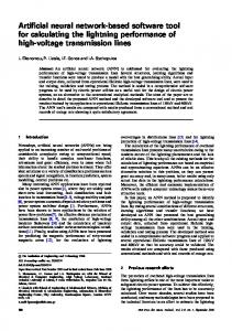
strategy method. In this case the new class is named according to the original host class of the method, with a unifying suffix (e.g. Storage(1) in Fig. 10). For Adapter, the adapter class is named simply “Adapter”, with a unifying suffix. VII. EFFICIENCY A potential drawback of using the GA approach is performance: the evolution of large populations of complex individuals might be time-consuming. Since we aim at an interactive tool which aids the architect in exploring different kinds of solutions with different parameters, the execution of the evolution should not be too slow. In our tool, the user can choose between two modes: fast mode with less history recording, and slow mode with full history recording. With fast mode, the execution time of a typical evolution is reasonable, taking into account that the architect can follow the development of the fitness curve in real time and stop the evolution when the fitness is no more improving. The time depends mainly on the size of the population (and naturally on the number of generations). A graph depicting the execution times when the tool was tested using an increasing set of population sizes is shown in Fig. 11. The target system was the same ACVM. The total amounts of generations were fixed at 100 in the tests. The highest value of execution time we observed was 96 seconds when population size had reached 300.
Figure 8. Fitness graph for ACVM
Figure 9. A fragment of family tree of an individual
The best architecture of the last generation can be regarded as the proposed architecture for the ACVM. A part of the proposed architecture for the system is presented in Fig. 10. As can be seen in the figure, certain patterns (adapter, strategy, and template method) have been introduced. The classes related to the introduced patterns are colored in the figure.
Figure 11. Efficiency with different population sizes
VIII. CONCLUSIONS Based on our earlier work on applying genetic algorithms for software architecture synthesis, we have devised a process model for developing a software architecture using this approach, and explored the required tool support to assist the process. We have developed a prototype tool called Darwin to test and demonstrate the tool ideas. Given that the ultimate goal is to automate substantial part of software architecture design in practice, the work in this paper represents only first steps. A necessary requirement for such a tool is tight integration with a conventional design environment with architectural modeling capabilities. Ideally, the tool should be also integrated with a large, constantly growing knowledge base of architectural solutions in a form that can be understood by the GA engine. In this way, the tool could
Figure 10. A fragment of proposed architecture for ACVM
For some of the patterns, new classes must be generated, and the real names of such classes cannot be inferred. For example, in the case of Template Method, the name of the required subclass is just “TemplateClass”, with a unifying suffix (e.g. TemplateClass7 in Fig. 10). Another example is Strategy: a new class (and interface) is generated for the
365
make use of community knowledge that is virtually impossible to master by a single human. We argue that in such a setup the tool not only automates the design process, but it can in many cases actually outperform a human architect who tends to be confined with a fairly limited set of solutions originating from his or her past experience. A major topic of our future work is the enabling of the use of existing architectures as input. We are also aiming to implement a support for preserving the given solutions (e.g., architectural styles) throughout an evolution.
[13] R. Lutz, “Evolving good hierarchical decompositions of complex systems,” Journal of Systems Architecture, vol. 47, 2001, pp. 613634. [14] S. Mancoridis, B.S. Mitchell, C. Rorres, Y.F. Chen, and E.R. Gansner, “Using automatic clustering to produce high-level system organizations of source code,” Proc. International Workshop on Program Comprehension (IWPC 98), USA, 1998, pp. 45-53. [15] J. McGregor, F. Bachmann, L. Bass, and P. Bianco, “Using ArchE in the classroom: one experience,” Technical Note, CMU/SEI-2007-TN001, 2007. [16] Z. Michalewicz, Genetic Algorithms + Data Structures = Evolutionary Programs, Springer-Verlag, 1992. [17] B.S. Mitchell, S. Mancoridis, and M. Traverso, “Search based reverse engineering,” Proc. 14th International Conference on Software Engineering and Knowledge Engineering (SEKE’02), 2002, pp. 431438. [18] M. O’Keeffe and M. Ó Cinnéide, “Towards automated design improvements through combinatorial optimization,” Proc. 4th Internation Workshop on Directions in Software Engineering Environments (WoDiSEE2004), W2S Workshop - 26th International Conference on Software Engineering, 2004, pp. 75 – 82. [19] M. O’Keeffe and M. Ó Cinnéide, “Search-based software maintenance,” Proc. Conference on Software Maintenance and Reengineering (CSMR'06), 2006, pp. 249-260. [20] M. O’Keeffe and M. Ó Cinnéide, “Search-based refactoring for software maintenance,” Journal of Systems and Software, vol. 81, issue 4, 2008, pp. 502-516. [21] O. Räihä, K. Koskimies, and E. Mäkinen, “Genetic Synthesis of Software Architecture,” Proc. 7th International Conference on Simulated Evolution and Learning (SEAL’08), Springer LNCS 5361, 2008, pp. 565-574. [22] O. Räihä, K. Koskimies, E. Mäkinen, and T. Systä, “Pattern-Based Genetic Model Refinements in MDA,” Nordic Journal of Computing, vol. 14, issue 4, 2008, pp. 322-339. [23] O. Räihä, K. Koskimies, and E. Mäkinen, “Scenario-based genetic synthesis of software architecture,” Proc. Fourth International Conference on Software Engineering Advances (ICSEA’09), 2009, pp. 437-445. [24] M. Shaw, and D. Garlan, Software Architecture - Perspectives on an Emerging Discipline, Prentice Hall, 1996. [25] ArchE WWW site. At URL http://www.sei.cmu.edu/architecture/tools/arche/index.cfm. Checked 15.3.2010. [26] Eclipse WWW site. At URL http://www.eclipse.org. Checked 11.3.2010 [27] Zest WWW site. At URL http://www.eclipse.org/gef/zest. Checked 11.3.2010 [28] OMG’s UML 2.2 WWW site. At URL http://www.omg.org/technology/documents/formal/uml.htm. Checked 12.3.2010 [29] Eclipse’s Model Development Tools WWW site. At URL http://www.eclipse.org/modeling/mdt . Checked 11.3.2010 [30] JFreeChart’s WWW site. At URL http://www.jfree.org/jfreechart. Checked 10.3.2010.
ACKNOWLEDGMENT This work is a part of the Darwin project, funded by the Academy of Finland. REFERENCES [1]
M. Amoui, S. Mirarab, S. Ansari, and C. Lucas, “A genetic algorithm approach to design evolution using design pattern transformation,” International Journal of Information Technology and Intelligent Computing, vol. 1, 2006, pp. 235-245. [2] P. Avgeriou, P. Kruchten, P. Lago, P. Grisham, and P. Dewayne, “Architectural Knowledge and Rationale - Issues, Trends, Challenges,” ACM Sigsoft Software Engineering Notes, vol. 32, issue 4, July 2007, pp. 41-46. [3] F. Bachmann, L. Bass, and M. Klein, “Preliminary design of ArchE: a software architecture design assistant,” Technical Report, CMU/SEI2003-TR-021, 2003. [4] W.J. Brown, R.C. Malveau, H.W. McCormickIII, and T.J. Mowbray, Antipatterns - Refactoring Software, Architectures, and Projects in Crisis, Jhon Wiley and Sons, Inc., 1998. [5] F. Buschmann, R. Meunier, H. Rohnert, P. Sommerlad, and M. Stal, Pattern-Oriented Software Architecture: A System of Patterns, vol. 1, John Wiley & Sons, August 1996. [6] S.R. Chidamber and C.F. Kemerer, “A metrics suite for object oriented design,” IEEE Transactions on Software Engineering, vol. 20, issue 6, June 1994, pp. 476-493. [7] J. Clarke et al., “Reformulating software engineering as a search problem,” IEE Proceedings - Software, vol 150, issue 3, 2003, pp. 161-175. [8] P. Clements, R. Kazman, and M. Klein, Evaluating Software Architectures, Addison-Wesley, 2002. [9] M. Di Penta, M. Neteler, G. Antoniol, and E. Merlo, “A language independent software renovation framework,” The Journal of Systems and Software, vol. 77, issue 3, 2005, pp. 225-240. [10] E. Gamma, R. Helm, R. Johnson, and J. Vlissides, Design Patterns: Elements of Reusable Object-Oriented Software, Addison-Wesley, 1995. [11] F.W. Glover and G.A. Kochenberger, Handbook of Metaheuristics, International Series in Operations Research & Management Science, 57th ed., Springer, 2003. [12] A. Jansen, J. Bosch, and P. Avgeriou, “Documenting after the fact: Recovering architectural design decisions,” The Journal of Systems and Software 81, 2008, pp. 536-557.
366