Toward Compositional Verification of Interruptible OS Kernels and Device Drivers Hao Chen
Xiongnan (Newman) Wu
Zhong Shao
Joshua Lockerman
Ronghui Gu
Yale University, USA {hao.chen,xiongnan.wu,zhong.shao,joshua.lockerman,ronghui.gu}@yale.edu
Abstract
1. Introduction
An operating system (OS) kernel forms the lowest level of any system software stack. The correctness of the OS kernel is the basis for the correctness of the entire system. Recent efforts have demonstrated the feasibility of building formally verified general-purpose kernels, but it is unclear how to extend their work to verify the functional correctness of device drivers, due to the non-local effects of interrupts. In this paper, we present a novel compositional framework for building certified interruptible OS kernels with device drivers. We provide a general device model that can be instantiated with various hardware devices, and a realistic formal model of interrupts, which can be used to reason about interruptible code. We have realized this framework in the Coq proof assistant. To demonstrate the effectiveness of our new approach, we have successfully extended an existing verified non-interruptible kernel with our framework and turned it into an interruptible kernel with verified device drivers. To the best of our knowledge, this is the first verified interruptible operating system with device drivers.
An operating system (OS) kernel serves as the lowest level of any system software stack. The correctness of the OS kernel is the basis for that of the entire system. In a monolithic kernel, device drivers form the majority of the code base; 70% of the Linux 2.4.1 kernel are device drivers [7]. Furthermore, such drivers are found to be the major source of crashes in the Linux and Windows operating systems [7, 5, 13]. While recent efforts on seL4 [21] and CertiKOS [14] have demonstrated the feasibility of building formally verified OS kernels, it is unclear how to extend their work to verify the functional correctness of device drivers. In CertiKOS [14], drivers are unverified, and it is not obvious how to extend their framework to model devices and interrupts. In a microkernel like seL4 [21], device drivers are implemented in user space, and, though its proofs guarantee driver isolation, it does not eliminate bugs in its user-level drivers. A major challenge in driver verification is the interrupt: a non-local jump to some driver code, triggered by a device. When device drivers are implemented inside the kernel (for better performance), the kernel should be interruptible; otherwise, it can lead to an unacceptable interrupt processing latency. Reasoning about interruptible code is particularly challenging, since every fine-grained processor step could contain a non-local jump, and, upon return, the machine state could be substantially changed. Even worse, it is not clear how such reasoning should be done at the C level, which is completely interrupt-unaware. Existing work either assumes that interrupts are turned off inside the kernel [14, 27], or polls the interrupts at a few carefully chosen interrupt points [21]. Furthermore, interrupt hardware is not static, but is configured by software. In order to verify any interesting device drivers (serial, disk, etc.), we first need to model the interrupt controller devices (e.g., LAPIC [17], IOAPIC [16]), and formally verify their drivers. This is important because, if the interrupt controllers are not initialized properly, it may lead to undesired interrupt behaviors. Device drivers also interact with interrupt controllers to mask/unmask particular interrupt lines. These issues have been overlooked in past work, where interrupt controllers are assumed to be properly initialized and their drivers are correctly implemented [2].
Categories and Subject Descriptors D.2.4 [Software Engineering]: Software/Program Verification—Correctness proofs, formal methods; D.3.3 [Programming Languages]: Languages Constructs and Features; D.4.5 [Operating Systems]: Reliability—Verification; D.4.7 [Operating Systems]: Organization and Design—Hierarchical design; F.3.1 [Logics and Meanings of Programs]: Specifying and Verifying and Reasoning about Programs General Terms guages, Design
Verification, Reliability, Security, Lan-
Keywords Program Verification; Certified OS Kernels; Interrupts; Device Drivers; Abstraction Layer; Modularity. Permission to make digital or hard copies of all or part of this work for personal or classroom use is granted without fee provided that copies are not made or distributed for profit or commercial advantage and that copies bear this notice and the full citation on the first page. Copyrights for components of this work owned by others than ACM must be honored. Abstracting with credit is permitted. To copy otherwise, or republish, to post on servers or to redistribute to lists, requires prior specific permission and/or a fee. Request permissions from
[email protected]. Copyright is held by the owner/author(s). Publication rights licensed to ACM.
PLDI’16, June 13–17, 2016, Santa Barbara, CA, USA ACM. 978-1-4503-4261-2/16/06...$15.00 http://dx.doi.org/10.1145/2908080.2908101
431
• We present a new extensible architecture for building certi-
Finally, verifying an interruptible operating system with device drivers also faces the following challenges. Devices and CPU run in parallel. Thus, the executions of CPU instructions and device transitions can interleave arbitrarily. Code verification on this highly nondeterministic machine can be challenging, since it needs to consider device state transitions, even when the CPU is executing a set of instructions unrelated to external devices. Recent work [1, 2, 3] tries to address this by enforcing a stability requirement that device states only change due to CPU operations. This requirement is, however, too strong as devices interacting with external environments are not stable: a serial device constantly receives characters through its port, a network card continuously transfers packets, an interrupt controller (IC) asynchronously receives interrupt requests, etc. Devices may directly interact with each other. Existing work assumes that a device driver monopolizes its underlying device and devices do not influence each other [2]. This assumption does not hold for many devices in practice. For example, most devices directly communicate with an interrupt controller by signaling an interrupt. Device drivers are written in both assembly and C. Existing device driver verification is either done completely at the assembly level [2, 9] or the verified properties are only guaranteed to hold at the C level [29, 30]. For realistic usecases, proven properties should be translated down and then formally linked with the assembly-level proofs. The correctness results of different components should be integrated formally. For example, the correctness proofs of device drivers and the OS kernel need to be formally linked as an integrated system, before one can deliver formal guarantees on the OS as a whole. Not doing so can introduce semantic gaps among different modules, a scenario which introduced actual bugs in previous verification efforts as reported by Yang and Hawblitzel [34]. Unfortunately, this formal linking process was found to be even more challenging than the correctness proofs of individual modules themselves [2]. Even OS’s with user-level device drivers can suffer if the correctness proofs of their drivers are not formally linked with those of the kernel. For example, if some device driver code triggers a page fault at the user level, the behavior of the corresponding driver is linked to the behaviors of the page-fault handlers and address translation mechanism of the kernel. In this paper, we propose a novel compositional approach that tackles all of the above challenges. There are two key contributing ideas. One is to build up a certified “virtual” device hierarchy, and another is a new abstract interrupt model, built upon a realistic hardware interrupt model through contextual refinement. We use these to build an extensible framework that systematically enforces the isolation among different operating system modules, which is important for scalability of any verification effort and critical for reasoning about interruptible code. Our paper makes the following new contributions:
fied OS kernels with device drivers. Instead of mixing the device drivers with the rest of the kernel (since they both run on the same physical CPU), we treat the device drivers for each device as if they were running on a “logical” CPU dedicated to that device. This novel idea allows us to build up a certified hierarchy of extended abstract devices over the raw hardware devices, meanwhile, systematically enforcing the isolation among different “devices” and the rest of the kernel. • We present a novel abstraction-layer-based approach for
expressing interrupts, which enables us to build certified interruptible OS kernels and device drivers. Our formalization of interrupts includes a realistic hardware interrupt model, and an abstract model of interrupts which is suitable for reasoning about interruptible code. We prove that the two interrupt models are contextually equivalent. • We present, to the best of our knowledge, the first verified
interruptible OS kernel and device drivers that come with machine-checkable proofs. The implementation, modeling, specification, and proofs are all done in a unified framework (realized in the Coq proof assistant [32]), yet the machine-checkable proofs verify the correctness of the assembly code that can run on the actual hardware. The rest of this paper is organized as follows. Sec. 2 gives an overview on how we build our device hierarchy while enforcing isolation from the rest of the kernel. Sec. 3 defines a formal machine model extended with raw hardware devices. Sec. 4 presents the device objects, hardware interrupt model, and abstract interrupt model, and shows how we prove contextual refinement between the two interrupt models. Sec. 5 presents two case studies of our verified drivers: one for a serial port and another for the interrupt controllers. Sections 6 and 7 give an evaluation of our new techniques and describe the lessons we learned, the limitations, and future work. Finally, we discuss related work and then conclude.
2. Overview of Our Approach Instead of verifying an operating system from scratch, we start from an existing verified kernel. Gu et al. [14] presented a compositional framework for building certified abstraction layers with deep specifications. There, a certified layer is a new language-based module that consists of a triple pL1 , M, L2 q plus a mechanized proof object showing that the layer implementation M , built on top of the interface L1 (the underlay), is a contextual refinement of the desirable interface L2 above (the overlay). A deep specification L2 of a module M captures everything contextually observable about running the module over its underlay L1 . Once a certified layer M with a deep specification L2 is built, there is no need to ever look at M again, since any property about M can be proven using L2 alone. Using this framework, Gu et al. [14] have successfully verified an OS kernel called mCertiKOS.
432
Disk
PCI Device ... PCI Device
AHCI
PCI Root Serial
Hardware Global Data
Kbd
Driver
...
Console Buffer
Serial
PCI NIC
AHCI / SATA (Disk)
PCI Function List
USB
LAPIC IOAPIC IOAPIC
Memory
DMA Ownership
LAPIC
mptable
APIC
DMA
IDT BIOS
CPU
TSC
Memory mapped reg base
Heap
CPU freq
Legend
Console
Keyboard
Timer
Video VGA (Video)
drive Use
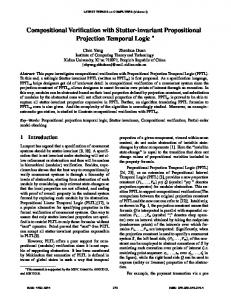
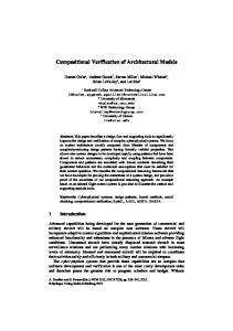
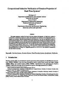
Figure 1. The device driver hierarchy of mCertiKOS The mCertiKOS kernel currently runs on the 32 bit x86 architecture. It provides a multi-processing environment for user-level applications using separate virtual address spaces. It implements both message passing and shared memory inter-process communication protocols. As a hypervisor, it can also boot recent versions of unmodified Linux operating systems inside a virtual machine. Unlike large commercial operating systems like Linux or Unix, mCertiKOS kernel only implements a small subset of the POSIX-like API, e.g., process creation and control, physical and virtual memory management, and inter-process communication. It does not implement signals, pipes, etc. The current file system implementation in mCertiKOS is not certified. Figure 1 shows the device hierarchy of mCertiKOS. Here the black boxes represent raw hardware devices; the green boxes denote the device drivers, and the gray boxes are the data structures used by the drivers. The purple/black lines show how these device and driver components are related. Note that the drivers in mCertiKOS are not verified; they are implemented in about 1,600 lines of C and assembly code, and would be considered as part of the trusted computing base (if they are kept inside the kernel). We take mCertiKOS’s lowest level machine model, LAsm, and extend it with device models. We model devices as finite state transition systems interacting with the processor and the external environments. Since devices run concurrently with the processor, parts of the device state change without the processor explicitly modifying them. Though these “volatile” device states can change nondeterministically, the processor itself only ever observes a “current” state when it reads the device data via an explicit I/O operation. The processor does not, and in fact cannot, care about any states that the device may enter between these observed states. Therefore, instead of designing fine-grained small-step transition systems that model all possible interleaved executions amongst the processor and devices, our devices simply perform an atomic big-step transition whenever they are observed, i.e., when there is a device read/write operation from the CPU. Next, the machine model needs to be extended with the hardware interrupt model. The processor responds to an in-
terrupt by temporarily suspending the current execution and then jumping to another routine (i.e., an interrupt handler). Interrupts can be triggered by both hardware and software. Software interrupts (e.g., exceptions, system calls) are relatively easy to reason about, since their behaviors are always deterministic. For example, a page fault exception occurs whenever the accessed address belongs to an unmapped page or a page with wrong permission, and a system call is triggered by an explicit instruction. However, hardware interrupts (IRQs) are unpredictable; when we execute some code with interrupts turned on, at every fine-grained processor step, the machine state (e.g., registers and memory) may undergo significant changes. Recent work on verified operating systems (including mCertiKOS) neglects this kind of reasoning, ignoring one of the largest kernel threat-surfaces [14, 20, 3]. Finally, modeling interrupts is important because it also opens the way toward enabling interrupts within the kernel. On top of this lowest-level machine model, each kernel module can be related to either device drivers (denoted as DD) or the rest of the kernel (denoted as K, representing non-device-related kernel components). To introduce, verify, and abstract each such kernel module into an abstract object with atomic logical primitive transitions, we need to prove the following isolation properties: • For each function in K or user space, which has interrupts
turned on, the interrupt must not affect the behavior of the function. Although the code can be interrupted at any moment, and the control flow transferred to a place outside the function, it will eventually return with states (which the function relies upon) unchanged. • Devices which directly change the memory through Direct
Memory Access (DMA), do not change any memory that the execution of any function in K depends on. • For each interruptible device driver function in DD, any
interrupt not related to the current device must not change any state related to the current device. • In case that all interrupts related to a device are masked
out, no interrupts can affect the state of the interrupt handler for the device.
433
DSerial
P
module ::
P
puts() {
... }, ...
DSerialIntro
...
P
module ::
?
c_init() {
... }, ...
Figure 3. The driver as an extended device
CPU
Hardware link
r ead/ wr i t e
(+) state
MBoot
P
Raw Device Object local trans state logs
( +) pr i mi t i v es
code
MContainer
P
Legend
Extended Device Object (Driver)
?
context code
P
Memory
module interleave
Context implement
D1
D2
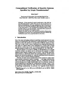
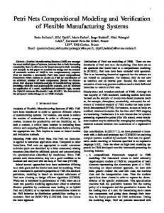
be manipulated via explicit calls to the device interface. We repeat these procedures so we can incrementally refine a raw device into more and more abstract devices by wrapping them with the relevant device drivers (see Fig. 3). In the rest of the paper, we call this extended abstract device a device object, to distinguish it from the raw hardware device. Note that in our model, device objects are indeed treated similarly to raw devices, and both have quite similar interfaces. Second, we introduce and verify the interrupt handler for each device at the lowest machine model, which is not yet suitable for reasoning about interruptible code. This is possible because, for each device, we require that either the interrupt be disabled or its corresponding interrupt line be masked inside the interrupt handler of the device. Next, we introduce a new abstract machine with a more abstract interrupt model, that provides strong isolation properties amongst different device objects and the kernel, in which any future (context) code with interrupts turned on can be reasoned about naturally. We prove a strong contextual refinement property between these two abstract machines: any context code running on the machine with the abstract interrupt model (overlay) retains an equivalent behavior when it is running on top of the machine with the concrete hardware interrupt model (underlay). Figure 4 shows the layer hierarchy of our interruptible kernel with device drivers. We treat the driver code as if it runs on its own device’s “logical CPU,” and each logical CPU operates on its own separate internal states. Thus, the approach provides a systematic way of assuring isolation among different device objects (running on its own local logical CPUs) and the rest of the kernel. On the kernel side (the layer hierarchy on the left hand side of Fig. 4), the contextual refinement is achieved in the same way as in Gu et al. [14] since the hardware interrupts (from the other logical CPUs with separate states) no longer affect the execution of any kernel primitive (like c_init), i.e., the kernel is completely interrupt-unaware. Similarly, the device driver functions are no longer affected by the hardware interrupts triggered from other devices. For each device D running on top of its own logical CPU, we first introduce and verify part of the driver in the critical area, i.e., the low-level device functions that should not be
Layer use
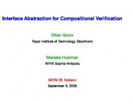
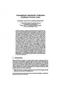
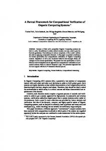
refine
Figure 2. Abstraction layers w. interrupts: a failed attempt For a particular fixed set of functions, the proof of the above properties may not seem hard. However, they have to be proven repeatedly for all possible combinations of currently introduced sets of functions and devices. This immediately makes the verification of an interruptible operating system with device drivers unscalable. Furthermore, it is not obvious how to apply techniques of Gu et al. [14] to handle hardware interrupts. Figure 2 shows one such attempt. Here, P denotes the kernel/userlevel context code; MBoot, MContainer, DSerialIntro, and DSerial denote several kernel and driver layers. With interrupts turned on in the kernel, it is immediately unclear how to show contextual refinement among different layers. For a kernel function like c_init, it cannot be easily refined into an atomic specification as the code can be interrupted at any point during the execution by a device interrupt, unless all possible interleaving of interrupts are encoded into the specification itself. Similarly, for a device driver function like puts, the code can be interrupted at any moment by interrupts triggered from other devices or the device itself. In this paper, we propose a systematic way that strictly enforces isolation among different entities by construction. Our approach consists of the following two key ideas. First, rather than viewing drivers as separate modules that interact with the CPU via in-memory shared-state, we instead view each driver as an extended device. We utilize abstraction layers and contextual refinement to gradually abstract the memory shared between a device and its driver into the internal abstract states of a more general device. Furthermore, we use the same technique to abstract those driver functions that manipulate these data into the abstract primitives of a higher level device. After this, our approach ensures that those abstract states can no longer be accessed by the other entities, through, e.g., memory reads and writes, but, rather, can only
434
... ...
P P P
P
... ...
D1_Puts module ::puts() { D1_Intr
MShareOp
...
D1_Func
MContainer
} D2_Intr
...
D2_Func
...
Legend Hardware critical area logical hw
P P
module ::c_init() {
}
CPU
}
module ::f2() {
D1 logical memory
Kernel logical memory
Memory
}
D2 logical memory
logical CPU 1
module Context
D2_Raw
D1_Raw
MBoot logical CPU 0
module ::f1() {
Layer
logical CPU 2
States
link interleave sequential implement use refine logical separation
D2
D1
Figure 4. Building certified abstraction layers with hardware interrupts: our new approach interrupted by the same device, and the interrupt handler of the device. Next, we use contextual refinement to introduce a new layer that has a more abstract interrupt model. On this layer, we can introduce and verify even interruptible driver code (e.g., puts) while still enforcing strong isolation and providing clean interface to the kernel.
environment, such as the keyboard or network, with specific transitions depending on the kind of event. When modeling these external events, we take a minimalistic approach: though the devices can receive all kinds of different external events, we only model those that change the observable behavior of the device. Thus, the events do not map one to one to the transitions in the device hardware but rather to the CPU observations on the hardware. We model the device interfaces, not the device internals. The device interface contains all the information that a programmer can know about its states. Some example events are:
3. Machine Model with Devices In this section, we present our machine model, which is based on the Intel x86 architecture. We start from the LASM machine model presented in Gu et al. [14], and extend it to model devices and interrupts. Our devices are modeled as finite state transition systems interacting with the CPU and the external environments. Each read/write (input/output) operation initiated from the CPU triggers an atomic big-step transition in the corresponding device. Device transitions (i.e., trans in Fig. 3) are affected by two types of interactions, one by the CPU and another by external events.
Definition 2 (Device External Events). E ::“ (* UART device *) | Recv ps : list charq | NoSendingCompAck | SendingCompAck (* Keyboard device *) | KeyPressed pc : Zq | KeyReleased pc : Zq ¨¨¨
Device Transitions caused by the CPU The CPU may trigger a device transition through I/O instructions or memorymapped I/O operations. These operations can be categorized into the following two actions: input n output n v
A specific key is pressed A specific key is released
External events are unpredictable, as their causes are not controlled by the OS. We determinize the behavior of each device by parametrizing it with the set of all possible list of events ℓenv that will be processed sequentially when the CPU performs I/O operations on this device. The atomic transition function δ env takes an external event e as input and changes the device states accordingly. Note that events, even within a single device, can commute. For example, a serial port serves two roles: to receive user input and to send program output. Accordingly, among the events a serial device can receive are one for the reception of a new input string, and one signaling that some past output operation has been completed. Consider a function that first writes to a serial port, then waits until the write operation is
Definition 1 (CPU Operation on a Device). O ::“ |
UART receives string s Sending is not complete UART completes the sending
Read value from the register at address n Write value v to the register at address n
For every device, we define an atomic transition function δ CPU , which takes the current device state s and a CPU operation o, and returns the new state s1 . Note that δ CPU is not a CPU transition, instead, it is strictly a device transition triggered by a CPU I/O operation. Device Transitions caused by External Events Device transitions can also be caused by events from the external
435
Overlay
completed by repeatedly reading some relevant status register. During one of these reads the user might send new input to the serial port. It would be reasonable for the device to observe the corresponding Recv event during one of the register reads, but doing so would make verifying the write function unnecessarily complex; not only would a function need to handle its own logic, but it would also need to handle any other state transition the device could undergo, even if the result were not observable in the current function. To address this verification challenge, each device keeps a set of local logs ~ℓ “ tℓ1 , ...ℓk u, each of which is a strict prefix of ℓenv . The serial device from the example above could contain two local logs, one for input and one for output. Then when δ env receives an event that does not correspond to the currently processed action, the event can simply be skipped. When a later action observes a part of the device state which is affected by the event, that action will handle the event. In the serial port example, we would defer handling the Recv event until some process reads from the serial port. Every raw device provides two I/O primitives: read n and write n v. The read primitive first updates the device state based on the environmental device transition δ env with the next relevant external event in ℓenv , then returns a value from the new state, and finally does the transition δ CPU triggered by this read action. The write primitive first triggers the transition δ env to update the device state based on the next relevant external event, then performs the transition δ CPU initiated by this write operation. In the following, the function nextpℓenv , ℓi q finds the first relevant event e in ℓenv that has not yet been processed with respect to the local log ℓi , and returns the event e plus a new local log that is synchronized with ℓenv up to the event e. Now, we define the operational semantics of the set of device primitives formally. Let κ be the function retrieving the value of device register addressed by n, then we have: s1 “ δ env ps, eq pe, ℓ1i q “ nextpℓenv , ℓi q 1 2 CPU 1 res “ κpn, s q s “ δ ps , input nq readpn, s, ℓi , ℓ
1
s “δ
env
env
writepn, v, s, ℓi , ℓ
env
q “ ps2 , ℓ1i q
State
Primitive
Device
Data Invariant Underlay Memory Data
Use Driver Function
Device
Contextual Refinement
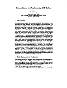
Figure 5. Layer-based contextual refinement driver code. At each abstraction layer, our model enforces systematic isolation among the different device objects and the rest of the kernel, so that interaction with one device object does not affect the states of other device objects nor the rest of the kernel. Thus, isolation properties are satisfied by construction. This dramatically simplifies our reasoning by allowing us, at any given time, to focus on only the device objects that are currently interacted with. In this section, we define the device object more formally; then we show how to incorporate interrupts into our model while still following our isolation policy. 4.1
Device Objects
A device object is a logical abstraction containing a hardware device plus its related drivers. Each device object consists of a set of abstract states, abstracting the private states of the device (e.g., device registers, driver private memory); and a set of primitives, abstracting the module interface. The abstract states are private to the device object, and can only be manipulated by explicit calls to the device object’s primitives. This is achieved by establishing a contextual refinement relation from the concrete memory and device function implementation to the abstract state and primitives. As shown in Fig. 5, we follow the layer-based methodology [14] and utilize the CompCert memory permissions [24] to hide the relevant memory at overlay, which prevents the context code from accessing the object’s private memory. These logical permissions do not correspond to any physical protection mechanism, but are used to ensure that the abstract machine at overlay gets stuck if any code tries to directly access this portion of memory. The safety proof of our entire operating system (the kernel never gets stuck) guarantees that such a situation never happens. The set of driver functions at underlay, which manipulate the memory that will be abstracted away at overlay, are themselves abstracted into the set of device primitives at the overlay (see Fig. 5). For example, the console buffer is implemented as a circular buffer in our console driver. The concrete implementations of the buffer operators (buf_read and buf_write) directly manipulate the concrete circular buffer in memory. At a higher layer, in our abstract console device object, the logical buffer is represented as a list, and the primitives are specified directly over this abstract list, i.e., the buf_read simply returns
(read)
q “ pres, s2 , ℓ1i q
pe, ℓ1i q “ nextpℓenv , ℓi q ps, eq s2 “ δ CPU ps1 , poutput n vqq
Memory
(write)
Thanks to the local logs, this machine model eliminates much of the nondeterminism that complicates reasoning about asynchronous systems. Nonetheless, it accurately models the observable behaviors of real hardware.
4. Driver Framework with Interrupts The processor inherently runs in parallel with devices. In Sec. 3, we have presented a machine model representing this level of concurrency. On top of this machine model, we build certified abstraction layers introducing more and more
436
Kernel/ User IC Dev
the head element in the list, while buf_write adds the new element to the end of the list, discarding a single head element if the size of the list exceeds its limit. The contextual refinement relation between the two layers ensures that any code running on top of the more abstract overlay exhibits behavior equivalent to running on top of the underlay. The primitives at the underlay can be passed through to the overlay, or hidden if they are no longer needed. For example, once the primitive ahci_transfer is introduced at the overlay, the underlay primitives ahci_read and ahci_write, used to implement ahci_transfer, are hidden. This facilitates the invariant proofs as stronger invariants can be introduced at higher layers, which could otherwise be violated by the lower-level primitives.
Event arrival
LASM Machine
Kernel/ User IC Dev
intr CPU intr IC
LASM Machine
pi Primitive called
intr_disable
D
Interrupt Controller
Event arrival
Combining Device Objects At a certain abstraction layer, some drivers, or more generally, system services, may interact with multiple device objects, by, e.g., transferring data between two devices, or broadcasting messages to multiple devices. At this stage, such devices are no longer totally isolated, but are synchronized through hardware or software mechanisms. This does not fit directly into our model providing systematic isolation among different device objects and the rest of the kernel. In the above scenario, we introduce at the overlay a single heterogeneous device object, which combines the device objects from the underlay via the newly introduced functions. The abstract machine at overlay thereby provides systematic isolation between the new abstract device object and the rest of the kernel. The internal states and local logs of the combined device object are the disjoint union of the relevant objects at underlay, while the functions that manipulate multiple device objects at underlay become primitives of the new device object, operating on a wider range of internal states, at overlay. As in all device objects, existing primitives can be either passed through to this new device, or hidden. 4.2
intr_handler
iret eoi
pi
intr_handler Interrupt Controller
mask Primitive called
D
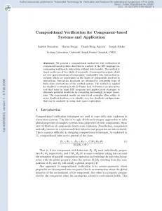
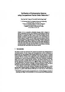
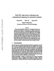
Figure 6. The hardware interrupt model (bottom), the abstract interrupt model (top), and the contextual refinement between these two models.
between these two abstraction layers to ensure that any context program running on top of the overlay retains behavior equivalent to running atop the underlay. Starting from the abstraction layer with the abstract interrupt model, we support verification of any code with interrupts enabled. 4.2.1
Hardware Interrupt Model
The entities involved in any given interrupts are categorized into three parties (shown in the bottom half of Fig. 6). If a device transition (e.g., from the device D in Fig. 6) triggers an interrupt, it gets sent to the IC. The IC multiplexes several interrupt lines onto the CPU (i.e., the LASM machine in Fig. 6), with the ability to mask and unmask each interrupt line. At each transition, the IC selects the pending unmasked interrupt with the highest priority and forwards it to the CPU. When the CPU receives an interrupt signal, it first checks whether interrupts are enabled on that CPU, and, if so, saves the current context and jumps to the corresponding entry in the interrupt descriptor table (IDT). If interrupts are turned off, the interrupt signal is ignored. Thus, an interrupt involves at most three consecutive transitions: the device, the IC, and the CPU. These three transitions seem inter-related, and isolation among the three entities is non-obvious. In our approach, we first develop a low level hardware interrupt model that separately defines the set of interrupt related operations. Then these three disconnected components are united at some higher level abstract machine model after we have verified all the interrupt handlers.
Interrupts
We now show how to adapt the interrupts into our setting. We first present our interrupt model at the hardware level, where the interrupt transitions are separately defined for the CPU, the interrupt controllers (IC), and the devices. At this low level we lack the full behaviors of interrupt handlers, so all the primitives verified at this machine level have the precondition that interrupts are disabled or the corresponding interrupt lines are masked. On top of this hardware abstraction layer, we incrementally introduce and verify interrupt handlers for each device through abstraction layers. Above a certain abstraction layer, we have full behaviors of the interrupt handlers, so we introduce a new abstraction layer with an abstract interrupt model, where an interrupt only changes the state of the device object that triggered it. This makes the interrupt completely transparent to the CPU, the IC, and other devices, thus guaranteeing our desired isolation properties. We prove the strong contextual refinement property
437
unmask, which set the sic .masksrND s of the interrupt line number ND to Masked and Unmasked respectively.
sic .masksrND s “ Masked sic .irqsrND s “ n intrIC psic , ND q “ psic , IRQ nq
sic .masksrND s “ Unmasked sic .irqsrND s “ n sic .ι “ H intrIC psic , ND q “ psic rι Ð ns, IRQ nq
(intrm IC )
Interrupt Transition for the CPU As soon as the IC marks an interrupt line as pending, the CPU will perform its own interrupt transition (e.g., see the purple box intrCPU along the Kernel/User line in Fig. 6). Let ρ represent the register set, and d be the logical abstract states in the machine model, then the interrupt transition of a CPU is shown in Fig. 8. We use EFLAGS.if to represent the interrupt flag bit in the EFLAGS register. If interrupts are disabled inside the CPU, the intrCPU primitive is totally transparent. Otherwise, it first changes the logical isr state to true, saves the current context into the end of the trap frame list (d1 rtfss), and jumps to the corresponding IDT entry. Here isr indicates whether the current machine execution is in the interrupt handling mode; the save_context function models the hardware behavior of saving the current context into the abstract state (d1 rtfss), which corresponds to the concrete stack frames in the memory (abstracted in layers below). The primitive iret is the counterpart of intrCPU , and models the behavior of CPU when the interrupt handler returns. It restores EFLAGS (including the old interrupt flag bit) from the context and thus also re-enable interrupts. The restore_context function models the hardware behavior of restoring the current context from the abstract state (drtfss).
(intruIC ) (eoi)
eoipsic q “ sic rι Ð Hs
Figure 7. Interrupt transition for the IC
ρrEFLAGS.ifs “ Disabled intrCPU pd, ρ, IRQ nq “ pd, ρq
ρrEFLAGS.ifs “ Enabled d1 “ drisr Ð trues 1 tfs “ save_contextpd1 rtfss, ρq 2 d “ d1 rtfs Ð tfs 1 s IDTrns “ p 1 ρ “ ρrEIP Ð psrEFLAGS.if Ð Disableds 2
1
intrCPU pd, ρ, IRQ nq “ pd , ρ q
(intrdCPU )
(intreCPU )
ptfs 1 , ρ1 q “ restore_contextpdrtfssq d1 “ drisr Ð falsesrtfs Ð tfs 1 s 1
1
iretpd, ρq “ pd , ρ q
Lemma 1. The function restore_context is a left inverse of the function save_context. ptfs, ρq “ restore_contextpsave_contextptfs, ρqq
(iret)
Figure 8. Interrupt transition for the CPU
The CPU also has two primitives sti and cli, which set the EFLAGS.if bit to Enabled and Disabled respectively.
Interrupt Transition for Devices As described in Sec. 3, every raw device has its own transition function δ env specifying how it reacts to the external events. When a particular transition triggers an interrupt (e.g., see the event arrival and the green box δ env along the Dev line in the bottom half of Fig. 6), the device marks an interrupt request bit (irq) in its internal state.
4.2.2
Abstract Interrupt Model
The low-level machine model, we just described, is not suitable for reasoning about interrupts, since each of the three entities has its own disconnected view. For instance, when the CPU jumps to an IDT entry, it is unaware of the behavior of the corresponding interrupt handler, and when the IC sends an interrupt signal to the CPU, it does not know whether the interrupt will be handled or not. We would like to formally connect these three different views to derive a nice machine model that is suitable for reasoning about the end-to-end behavior of interrupts, i.e., an interrupt triggered by a device only modifies the particular device’s internal states, and is transparent to the CPU, the IC, and other devices. To achieve this, we need a model of the full behavior of the interrupt handler for each device. Starting from the above hardware interrupt model, we incrementally extend a raw device by wrapping it with driver code related to the interrupt handler, until we have fully verified the interrupt handler for the device. Each device has exactly one interrupt handler, which, by our isolation policy, only modifies the internal states of its particular device, and cannot itself be interrupted by the same device.
Interrupt Transition for the IC When the IC receives an interrupt signal (e.g., see the orange box intrIC along the IC line in Fig. 6), it first checks whether the particular interrupt line is masked, and if so, it ignores the interrupt; if not, then the IC marks the corresponding interrupt line as pending. The transition rules are defined in Fig. 7. Here, ND is the corresponding interrupt line number of the device D which triggered the interrupt; it is fixed by the hardware connection, and is mapped to IRQ n by the configuration of the IC; the ι field of sIC indicates which IRQ number is pending; we use H to indicate that there is no pending interrupt. After the CPU performs its initial interrupt transition, the IC would receive the End Of Interrupt (EOI) signal (e.g., see the orange box eoi along the IC line in Fig. 6), it clears the pending mark on the interrupt line. The IC also has two primitives mask and
438
ps1ic , IRQ nq “ intrIC psic , ND q pd1 , ρ1 q “ intrCPU pd, ρ, IRQ nq 2 1 sic “ eoipsic q ps1D , ℓ1i q “ intr_handlerD psD , ℓi , ℓenv q pd2 , ρ2 q “ iretpd1 , ρ1 q
D ISABLE N O I NTR : Disable with no unhandled interrupt pe, ℓ1i q
env
env
“ nextpℓ , ℓi q stmp “ δ ps, eq stmp .irq “ false s1 “ sriFlag Ð 0s intr_disableps, ℓi , ℓ
env
q “ ps1 , ℓi q
intrpd, m, ρ, sic , sD , ℓi , ℓ
env
q “ pd2 , m, ρ2 , s2ic , s1D , ℓ1i q
D ISABLE I NTR : Disable with unhandled interrupts
Figure 10. Interrupt transition for the whole system, in the case when an interrupt is triggered by the device D on interrupt line number ND .
pe, ℓ1i q “ nextpℓenv , ℓi q s1 “ δ env ps, eq 2 2 s .irq “ true ps , ℓi q “ intr_handlerps1 , ℓ1i , ℓenv q 3 3 ps , ℓi q “ intr_disableps2 , ℓ2i , ℓenv q 1
intr_disableps, ℓi , ℓ
env
q “ ps3 , ℓ3 i q
til the device no longer attempts to trigger an interrupt within the interrupt handler, and normal execution can continue. With these two new primitives, the CPU transition in the abstract interrupt model can be completely oblivious of the device transitions. For example, in the top half of Fig. 6, the purple box along the Kernel/User line can ignore any event arrival from a device; the CPU for the Kernel/User line would only force the device transitions when it wants to make observations about a device (e.g., by calling intr_disable, then a high-level device primitive pi , followed by intr_enable).
E NABLE N O I NTR : Enable with no pending interrupt s.irq “ false
s1 “ sriFlag Ð 1s
intr_enableps, ℓi , ℓ
env
q “ ps1 , ℓi q
E NABLE I NTR : Enable with pending interrupts s.irq “ true ps1 , ℓ1i q “ intr_handlerps, ℓi , ℓenv q 2 2 ps , ℓi q “ intr_enableps1 , ℓ1i , ℓenv q intr_enableps, ℓi , ℓ
env
q “ ps2 , ℓ2i q
Contextual Refinement Between Two Interrupt Models To show the contextual refinement between the two abstraction layers in Fig. 6, we prove that the behavior of an IRQ can indeed be made transparent to the CPU and the IC.
Figure 9. Transition rules for intr_disable and intr_enable At this stage, we have the formal specification of the interrupt handler for a device. Next, through contextual refinement, we encapsulate the behaviors of interrupts into two primitives intr_enable and intr_disable at overlay for the device, which, as shown in the top half of Fig. 6, render interrupts transparent to the CPU and the IC. The precise transition rules are given in Fig. 9. Here, iFlag is an abstract state indicating whether the particular device interrupt is turned on or off; the next function, as defined at the end of Sec. 3, returns the next relevant event in ℓenv and a new local log synchronized with ℓenv up to the returned event. The intr_disable primitive first synchronizes the device state with the previously unhandled interrupts then sets interrupt as disabled. It performs the synchronization by scanning the log from the last place intr_enable was called, until we hit the first event that did not trigger any interrupt. This ensures that subsequent observations on the device (in the abstract model) will be consistent with those performed under the hardware interrupt model. Note that intr_disable is defined recursively: it performs the environment transition δ env on each event until we hit an event that does not trigger interrupts (i.e., the D ISABLE N O I NTR case); the stmp state should be discarded since the device transition stops at the point where the last unhandled interrupt is handled. The intr_enable primitive discharges any pending interrupts, then sets interrupt as enabled. This models the physical machine behavior, wherein interrupts (which can occur while interrupts are disabled) get delayed until interrupts are reenabled. This causes the OS to immediately jump to the interrupt handler after re-enabling interrupts. This repeats un-
Lemma 2. An IRQ is transparent to the CPU and the IC, i.e., the transitions triggered by the IRQ only change the states of the corresponding device that triggered the interrupt. Proof: When the interrupt is disabled on the CPU or the particular interrupt line is masked in the IC, the proof is obvious. When the interrupt is enabled, i.e., the corresponding interrupt line is routed, not masked, and the EFLAGS.if register bit is set, the state transition of the whole system is shown in Fig. 10. Here, the transition intr takes an abstract state d, the memory m, the register set ρ, the state of interrupt controller sic , the state of the device sD , a local log of the device ℓi , the event list ℓenv , and returns appropriate new system states after the interrupt transition is fully performed. In this case, we need to show that: pd1 , m1 , ρ1 , s1ic , s1D , ℓ1i q “ intrpd, m, ρ, sic , sD , ℓi , ℓenv q ps1D , ℓ1i q “ intr_handlerD psD , ℓi , ℓenv q^ d1 “ d ^ m1 “ m ^ ρ1 “ ρ ^ s1ic “ sic
This can be proven by composing the interrupt transition rules of the CPU and the IC with Lemma 1. Corollary 1. IRQs do not affect the kernel, i.e., they do not change any of the kernel’s states1 . Nested Interrupts Note that the intrCPU transition in Fig. 8 disables the interrupt. Thus between intrCPU and iret in Fig. 10, the interrupt is turned off, which means that no nested interrupts are allowed. In many cases, supporting 1 Remember,
439
we consider device drivers a part of the device, not the kernel.
s4 ic
controller and the connected cable. The UART controller is responsible for demodulating received data into digital bits and storing them into the internal receiving (Rx) buffer, and also modulating sent data from digital bits and inserting them into the transmission (Tx) buffer. The hardware UART controller has many features, and the mCertiKOS serial driver only utilizes those parts needed for sending and receiving character strings. When modeling the serial port, we take the minimalistic approach of only modeling the set of features utilized by the existing drivers. The internal state of the serial port device is defined as:
ps1ic , IRQ nq “ intrIC psic , ND q pd1 , ρ1 q “ intrCPU pd, ρ, IRQ nq s2ic “ eoips1ic q 3 2 sic “ maskpsic , ND q pd2 , ρ2 q “ stipd1 , ρ1 q 1 1 psD , ℓi q “ intr_handlerD psD , ℓi , ℓenv q pd3 , ρ3 q “ clipd2 , ρ2 q “ unmaskps3 pd4 , ρ4 q “ iretpd3 , ρ3 q ic , ND q
intrpd, m, ρ, sic , sD , ℓi , ℓ
env
1 1 q “ pd4 , m, ρ4 , s4 ic , sD , ℓi q
Figure 11. Interrupt transition for the whole system when nested interrupts are allowed.
s“p
Kernel/ User IC Dev
intr_handler
Event arrival
Kernel/ User IC Dev
sti
intr CPU intr IC
eoi mask
Event arrival
pi Primitive called
intr_disable
cli
iret
unmask intr_handler
pi
mask Primitive called
There are three external events for the serial device. The serial event Recv s indicates that a string has been received. The SendingCompAck event implies the device received the acknowledgment that the characters in the transmission buffer have been sent out successfully, while the NoSendingCompAck events indicates that the sending of characters in the transmission buffer is not yet complete. We have configured the serial device to trigger an interrupt when it receives data (a nonempty string). The device is configured to not to trigger any interrupt when the transmission buffer becomes empty, i.e., when the characters in the transmission buffer are sent out successfully. Thus, before any data is written to the serial port, we have to poll the transmission status until it becomes empty. We have chosen this setup because it covers both interrupt-triggering and polling events. Note that, the states s.RxBuf and s.irq are disjoint from s.TxBuf under the environment transitions in that the former is for receiving data and the latter is for sending data only. This allows us to use two separate local logs in our device model, ℓtx (for transmission) and ℓrx (for receiving), to handle these possibly commutative events. Next, in Fig. 14, we define the transition functions δ env and δ CPU , where δ env needs to handle all the possible environmental events against the current state, and δ CPU updates the current state based on the input and output addresses and values. We use the notations r¨s and ++ to represent a singleton list and list concatenation, respectively. The function last takes a length n and a list l, and returns the last n elements of l as a new list if the length of l exceeds n, and returns the original list l otherwise. The function is used to model the action of dropping some elements in the front of the buffer when the length of the new buffer exceeds the hardware buffer size (BufSize).
Figure 12. The contextual refinement between interrupt models with nested interrupts. nested interrupts is critical so that some high priority interrupt processing is not delayed by the low priority ones. The interrupt transition for the whole system with nested interrupts is shown in Fig. 11. Here, before the interrupt handler is called, we mask the interrupt line of the particular device (to make sure there is no nested interrupt from the same device) and then turn on the interrupt on the CPU. Accordingly, after the interrupt handling, we disable the CPU interrupt, then unmask the particular interrupt line before the iret transition is performed. We have proved that this model also refines the same abstract interrupt model (see Fig. 12).
5. Case Study In this section, we present two case studies of our verified drivers. First, we present our device model for a serial port, and show how the relevant drivers are specified and verified. Next, we present our interrupt controller model. We have used a single controller in Sec. 4 to ease the presentation. However, mCertiKOS utilizes two physical interrupt controller devices: the I/O Advanced Programmable Interrupt Controller (IOAPIC) and the Local Advanced Programmable Interrupt Controller (LAPIC). In this section, we only present the IOAPIC device model and the verification of its driver. 5.1
RxBuf : list char, Ź Receiving buffer TxBuf : list char, Ź Transmission buffer irq : bool, Ź Interrupt pending Connected : bool, Ź Power Base : Z, Ź Base address Ź Line and modem configurations: RxIntEnable : bool, DLAB : bool, Baudrate : Z, Databits : Z, Stopbits : Z, Parity : ParityType, FIFO : Z, Modem : Z q.
Serial Port
Fig. 13 illustrates a typical serial port with a bounded internal buffer of size 12. It consists of a RS-232 interface and a Universal Asynchronous Receiver/Transmitter (UART) controller. RS-232 delivers electrical signals between the UART
440
1 void serial_putc (unsigned int c) {
Internal Buses
unsigned int lsr = 0, i; if ( serial_exists() ){ for (i = 0; !lsr && i < 12800; i++) { lsr = serial_read(0x3FD) & 0x20; delay(); } serial_write (0x3F8, c); ...
2
UART Controller RS-232 6 7 8 9
1 2 3 4
irq
TxBuf
Base
RxBuf
Databits
DLAB
Fifo
Baudrate
Parity
Stopbits
5
3
CPU
4 5 6 7
RxInt Enable
8 9
Figure 15. The implementation of serial_putc in C Figure 13. The hardware connections of a serial port 1 void serial_puts(char * s, int len) {
int i = 0; while (i < len && s[i] != 0) { serial_intr_disable(); serial_putc(s[i]); serial_intr_enable(); i++; }
2
s.Connected “ true s.RxIntEnable “ true e “ Recv w w ‰ nil newBuf “ lastpBufSize, ps.RxBuf ++wqq δ env ps, eq “ srRxBuf Ð newBufsrirq Ð trues
3 4 5
(recvd)
6 7 8
s.Connected “ true s.RxIntEnable “ true e “ Recv w w “ nil δ env ps, eq “ s s.Connected “ true
e “ SendingCompAck
δ env ps, eq “ srTxBuf Ð Hs s.Connected “ true e “ NoSendingCompAck δ env ps, eq “ s s.Connected “ true o “ input n n “ s.Base ` 0 s.DLAB “ false s.RxBuf “ w δ CPU ps, oq “ srRxBuf Ð tl wsrirq Ð falses s.Connected “ true o “ output n v n “ s.Base ` 0 s.DLAB “ false s.TxBuf “ w δ
CPU
ps, oq “ srTxBuf Ð lastpBufSize, pw++rvsqqs
9 }
(norcv)
Figure 16. The implementation of serial_puts in C function serial_putc is specified as follows:
(sent)
s.TxBuf “ H s.serial_exists “ true s1 “ srTxBuf Ð rcss pe, ℓ1tx q “ nextpℓenv , ℓtx q pe1 , ℓ2tx q “ nextpℓenv , ℓ1tx q
(noack)
serial_putcps, c, ℓtx , ℓ
env
q “ ps1 , ℓ2tx q
s.TxBuf ‰ H s.serial_exists “ true pe, ℓ1tx q “ nextpℓenv , ℓtx q s1 “ δ env ps, eq 2 2 1 ps , ℓtx q “ serial_putcps , c, ℓ1tx , ℓenv q
(read)
serial_putcps, c, ℓtx , ℓ
env
q “ ps2 , ℓ2tx q
The first rule above shows the case when the transmission buffer is originally empty. Here, lsr immediately becomes 1 in the first loop iteration, and the character is written to the transmission buffer in the device right away. The second rule above shows the case when the initial transmission buffer is not empty. Here, the device performs transition based on the received event e, and repeats the same process until it finally receives the SendingCompAck event. Then, by definition of δ env in Fig. 14, the transmission buffer becomes empty and the next recursive call falls into the first case of the specification. In Fig. 16, we show the implementation of the driver function serial_puts that writes a string into the serial device by repeatedly calling serial_putc for each character in the input string. Each call to serial_putc is wrapped with calls to serial_intr_disable and serial_intr_enable (both derived from those in Fig. 9) to protect the critical section. Most of our drivers are implemented in ClightX [14], which is an extension of the CompCert Clight language [23] with abstract states and primitives. For each driver function,
(write)
Figure 14. The environment and CPU transition functions
By instantiating the device state and transition functions from our general device model in Sec. 3, we create a concrete model of the serial port with the read and write primitives. Next, we show how the drivers are specified and verified on top of this model. Fig. 15 shows a code fragment of the function serial_putc. There, the serial_read and serial_write are the two primitives in the serial hardware model, while serial_exists is a new primitive (already verified in some underlay) indicating whether the serial device is already initialized. The if statement (line 3) prevents any misuse of serial_putc() before initialization. If the s.TxBuf buffer is initially empty, or the device receives a SendingCompAck event during the loop (line 4-6), the program sends the character c to the serial port (line 8). The
441
Processor Core Local APIC MaxLvt Spurious
Esr Pending
Enable
Lint0
s.ι “ None w “ IRQ n s.masksrns “ Unmasked
Lint1
δ intr ps, wq “ srι Ð Some pq, dqs
...
s.ι “ None w “ IRQ n s.masksrns “ Masked
APIC Bus PCI Device
PCI Device
Current Base
MIRQ
Device
δ intr ps, wq “ s
I/O APIC
PCI Bus
Platform irqs Controller Hub
Id
s.irqsrns “ q s.destsrns “ d
s.ι “ Somepq, dq w “ EOI s.irqsrns “ q s.destsrns “ d
Redirect table
δ intr ps, wq “ srι Ð Nones
(delivered)
(masked)
(EOI)
MaxIntr
Figure 19. IOAPIC transition rules ISA Bus
Figure 17. The hardware connections and registers of APIC
1 void ioapic_init(void) {
int j = 0, maxintr = ioapic_read(1) >> 24; while(j