Toward Developing Reusable Software Components for Robotic Applications Issa A.D. Nesnas Richard Volpe Tara Estlin Hari Das Richard Petras Darren Mutz Jet Propulsion Laboratory California Institute of Technology M/S 198-219, Pasadena, California 91109 Phone: 818-354-9709 email:
[email protected]
Abstract We will present an overview of the CLARAty architecture which aims at developing reusable software components for robotic systems. These components are to support autonomy software which plans and schedules robot activities. The CLARAty architecture modifies the conventional threelevel robotic architecture into a new two-layered design: the Functional Layer and the Decision Layer. The Functional Layer provides a representation of the system components and an implementation of their basic functionalities. The Decision Layer is the decision making engine that drives the Functional Layer. It globally reasons about the intended goals, system resources, and state of the system and its environment. The Functional Layer is composed of a set of interrelated object-oriented hierarchies consisting of active and passive objects that represent the different levels of system abstractions. In this paper, we present an overview of the design of the Functional Layer. The Functional Layer is decomposed into a set of reusable core components and a set of extended components that adapt the reusable set to different hardware implementations. The reusable components: (a) provide interface definitions and implementations of basic functionality, (b) provide local executive capabilities, (c) manage local resources, and (d) support state and resource queries by the Decision Layer.
1 Introduction With the increased interest in developing rovers for future Mars exploration missions, a significant number of rover platforms have been designed and built in the last few years. Researchers and engineers at the Jet Propulsion Laboratory, California Institute of Technology, NASA Centers, and universities use these platforms to test new concepts and validate algorithms for the control and operation of autonomous robotic vehicles. Because of the differences in the mechanical and electrical design of these vehicles, they share little in terms of software infrastructure. Transferring capabili-
ties from one rover to another has been a major and costly endeavor because: (i) physical capabilities differ from one rover to another, (ii) rovers have different control and software architectures, and (iii) rovers are complex systems that integrate many disciplines. Because robotics systems cover several domain areas, researchers of a single domain need to integrate their newly developed technology into the complex robotic environment. Proper integration requires an in-depth understanding and characterization of the behavior of various components of the system, which vary from one platform to another. The CLARAty architecture, which stands for Coupled Layered Architecture for Robotic Autonomy, aims at developing flexible and reusable software components for robotic systems [20]. These components are intended to support autonomy software which plans and schedules robot activities. The CLARAty architecture modifies the conventional threelevel robotic architecture into a new two-layered design: the Functional Layer and the Decision Layer. The Functional Layer provides a representation of the system components and an implementation of their basic functionalities. The Decision Layer is the decision making engine that drives the Functional Layer. One of our goals is to provide a design that allows nonexperts in a domain to use and integrate these components in their applications. To do so, we need to capture wellunderstood and well-developed knowledge from the various domains into generalized components. Just like an operating system provides a level of abstraction from the computational hardware, so does the Functional Layer provide a level of abstraction for the robotic systems.
2 Background There has been several efforts focused on developing robotic architectures. Typical robot and autonomy architectures are comprised of three levels - Functional, Executive, and Planning levels [1] [10] [17]. Some architectures emphasized one area over others and thus became more dominant in that
domain. For example, some architectures emphasized the planning aspects of the system [7] [8], others emphasized the executive [4] [18], while others emphasized the functional aspects of the system [19] [14] [16]. There is ongoing research in activities aimed at blurring the distinction between the planning and executive layers [9] [11]. Other architectures did not explicitly follow this typical breakdown. Some focused on particular paradigms such as a fuzzy-logic based implementation [12] or a behavior-based implementation [2] [5]. There has been considerable effort in architectures that addressed multiple and cooperating robots [15] [13]. One difference between the CLARAty architecture and the conventional three-level architectures is the explicit distinction between levels of granularity and levels of intelligence. In conventional architectures both granularity and intelligence were aligned on one axis. As you move to higher abstractions of the system, intelligence increases. This is not true for the CLARAty architecture, were intelligence and granularity are on two different axes. In other words, the system decomposition allows for intelligent behavior at very low levels while still maintaining the structure of the different abstraction levels. This is similar in concept to hybrid reactive and deliberative systems.
3 A Component-Based System Decomposition 3.1 Exposing Behavior or Runtime Model The proper decomposition for a generic robotic system, in large, depends on what elements of the software are targeted for reuse in future applications. One decomposition, for example, can highlight the runtime model of the system, while another can highlight the behavior of the components of the system hiding the runtime models and their implementations. Under different hardware architectures, the runtime implementation of components may change making it desirable for encapsulation. The ControlShell software [16], for example, is a commercial package that highlights the runtime behavior of a system providing a close monitoring of its runtime models. Alternatively, our decomposition highlights the behavior of the components of the system while hiding their runtime models and their implementation details. The behavior of components is usually less likely to change across applications and hence can be abstracted into a generic form. To illustrate this point, consider the example of a motion control system which can be represented by generic Motor and CoordMotors components. Every robot system has an internal motion control architecture that reflects the control hardware. Each hardware component introduces architectural constraints on the system. In one implementation, one might use commercial off-theshelf (COTS) motion control boards. In a second implementation, one might use custom designed boards with COTS
chips. In a third implementation, one might close the feedback loop using software running on an embedded processor. While these are three different implementations of a motion control system, the behavior requirements of the controlled motor are the same. In any of these implementation, you would still like to do position commanding, velocity profiling, and trajectory control. You would also like to detect and report stall conditions and be able to interrupt the motion. You would also like to read the current and desired positions, velocities, accelerations, and health status. For a person developing vision-based navigation component for a mobile robot, it is only necessary to understand the behavior of the component rather than be required to have intimate knowledge of the implementation and hardware details. Nor should they have a particular implementation inadvertently influence their design of vision-based navigation algorithms. The Motor and CoordMotors are an abstract representation for motion control that define what the components are supposed to do. These components hide the details of the implementation without compromising particular features of the hardware. Another example is that of an imaging system. The primary function of such a system is to acquire images. How the imaging system acquires the image depends, largely, on its implementation. In some systems, an analog camera is connected to a framegrabber mounted in a computational backplane. In other systems, a digital camera is used and the image is transmitted through a fast serial interface directly to the host memory. In either case, the primary function of the imaging system remains the same, i.e. to acquire images. We can represent such a system by an abstract Camera component that publishes a uniform interface for acquiring and synchronizing image acquisition but hides the details of its implementation and the runtime models.
3.2 Component Classification We will present a classification based on the abstract physical and functional components of the system that we have been evolving over several years. We use an object-oriented system decomposition to provide several abstractions for the components of the systems. Physical abstract components are extended to concrete components that tie into realsystem or to simulation components that tie into virtual systems. Components are implemented using classes. The terms are used interchangeably in this article. There are three main types of classes in our Functional Layer: (1) data structure classes, (2) generic classes (physical and functional), (3) specialized classes (physical and functional). All three types of classes contain domain knowledge from different disciplines. They are integrated in a framework to maximize code reuse, eliminate duplicated functionality, and simplify code integration. As a result, there are relationships and dependencies among the various classes. Together they provide a modular but well-integrated solution. Next, we will describe these different types of classes.
Rover IO
Instrument
CoordMotors Locomotor
Digital_IO Analog_IO
Manipulator
LeggedLoc RBLoc WheeledLoc Arm VisualTracker VisualNavigator StereoGen Camera
Motor
Correlator FeatureDetector ControlledMotor
Mast Socket
BBMotor
SocketMsg
Resource
Behavior
Specialized Data Structures ColorImage
Image
General Purpose Data Structures String
Container
Pixel
HTrans
Array_2D Matrix Vector
Location
State
Database Point
LinkedList
Bit
Standard Template Library
Figure 1: Various classes useful for robotic applications A description of the relationships among these components will follow.
3.3 Relationships among the Different Components There are two types of relationships among these components: inheritance, and aggregation [6]. As we have just seen, the relationship between generic and specialized components is that of inheritance. Specialized classes are derived from the generic classes. Both generic and specialized classes are of the same type. In aggregation, however, the aggregated component has a different type than that of the aggregate. Aggregation is used to provide components with different levels of granularity. For example, a Manipulator class aggregates lower-level Motor class and Link class objects. The reason why such a decomposition of robotic systems is possible is that components at the lower levels of granularity can be implemented with little or no knowledge of their neighboring components. In other words, the coupling among low-level components is loose for the most part. The coupling among these components increases as we move to higher-level components. Higher-level components aggregate lower-level components and manage the interaction of their subordinate components. This approach abstracts the functionality of components and reduces the complexity of the system significantly.
4 Data Structure Classes The data structure classes are classes that provide handling, transformation, and storage of data. One characteristic of data structures is that they do not have any executive ca-
pability, making them the easiest to implement and port on multiple operating systems. While their efficiency is very important, they themselves do not invoke other threads (tasks). However, they must be reentrant to support being simultaneously executed by different threads. Data structures are the most reused components in the system. There is not a single data structure that dominates in the architecture; but there are several types that are used throughout the Functional Layer. The challenge in the design of data structures is to enhance their reusability across the different robotic domains. There are two types of data structures relevant to our discussion: (1) general-purpose data structures, and (2) domain-specific data structures. General-purpose data structures are reusable beyond the scope of robotics applications. Therefore, whenever suitable, we leverage standardized developments of these general data structures, such as the Standard Template Library [3]. Whenever such implementations are not available for real-time operating systems, or whenever they impose constraints that are not appropriate for robotic applications, we replace them with alternative customized implementations maintaining the same interface. Examples of general-purpose data structures are: Array, Vector, Matrix, Bit, LinkedList, Map, Container, String and so on. Examples of domain specific data structures are: Image, Message, Resource, Location, HTrans(homogeneous transformation), Quaternion and so on. Some domains impose certain constraints on the design and implementation of their data structures. For example, a two-dimensional array class created by instantiating a vector of a vector using the vector class of the Standard Template Library (STL) cannot serve as a parent for our Matrix class, which in turn is a parent class for our Image class. The Image and Matrix classes must have
Type
Type
Array_2D
Bit
Generic Physical Comp
Point
Public Type
Queries
Matrix
Object Services
Creates Links to
Sub-object
Objects HW Object Members Type Vector
Type HTrans
State State State 1
PixelType Image
State Handler Internal Implementation
Type Location
PixelType ColorImage
State Machines
Local Estimation
Private
Figure 2: The Arrayclass hierarchy Estimator
contiguous memory allocations of their elements for efficient processing. The processing requirements of these two derived classes impose certain constraints on the design of their base class. In other words, a trade-off is made in favor of efficiency over flexibility of the data structure, which influences the design of the Array/ Matrix/ Image hierarchy. Figure 2 shows the current relationships between these data structures expressed using the Unified Modeling Language (UML) [6].
5 Generic Classes Generic classes are classes that provide an abstract description and implementation of the behavior of a component. Generic classes can be active, i.e. their objects can generate separate threads of execution and run within multiple threads. In other words, these classes can have local executive capability. For example, a Motor class can generate two threads of execution: one for control and the other for feedback. Some classes also have local planning capabilities. There are two types of generic classes: generic physical classes (GPC) and generic functional classes (GFC).
5.1 Generic Physical Classes A generic physical component (GPC) is a class that defines the structure and behavior of a physical object in an abstract sense. These type of classes expose the capabilities of the components independent of the underlying hardware configuration. Some of these classes have partial implementations since they are eventually attached to physical/simulation objects that complete their implementation. The objects to which they attach are of the same type. The extent of the implementation depends on the knowledge available to that class at that particular level of abstraction. Examples of such classes are: Motor, Joint, Wheel, Arm, Mast, Locomotor, Rover, Camera, FilterWheel, Gyro, DigitalIO, AnalogIO, Socket, and SunSensor. These components appear at different levels of granularity in the Functional Layer. Figure 3 shows an illustration of a
- optional link
Figure 3: A typical generic physical component structure typical generic physical component. The characteristics of these generic components are that they: Represent an abstract view of a physical entity. Attach to concrete physical classes of the same type. The physical classes complete the implementation of the generic class interface. Provide generic public interfaces that supports different physical implementations. The interfaces define the functionality and services of the component. Provide the runtime model for component’s operation. Manage local atomic resources and resolve local conflicts. Encapsulate the states of a component and provide access to the states through their public interface. The Decision Layer can query any state of a component at any time. Provide local state estimation based on information available within the scope of the component. May attach to external generic estimators (e.g. Kalman Filter) Provide resource usage prediction in response to queries from the Decision Layer. May have internal state machines. May include or reference other generic physical components. Such components are made publicly accessible to allow access to subordinates. 5.1.1 The State and StateHandler Classes Components use state variables for logging, tracking, and recovery strategies. Components can have numerous state
variables depending on what states are interesting to a particular application. State information can have different forms. It may be contained in a software variable or a hardware register. To track hardware registers, state variable are created to mirror these registers. Doing so enables tracking and logging of a particular state for planning and recovery purposes. Typical components can have tens of states. A State class is designed to provide a uniform handling of all state variables. The State is a templatebased class that wraps the actual state variable. State variables can be represented by integers, vectors, matrices, bit patterns, and so on. The State class tracks transitions, time-tags and logs state history. Internal state machines keep track of current states and allowable state transitions. The State class can attach to an external StateHandler class, which provides additional global functionality such as the periodic monitoring of any selected subset of the system’s states. Such state tracking can be selectively disabled or completely eliminated for applications that do not require this feature. State information can only be accessed through the state query interface. States can be internally monitored by the component or externally monitored by the StateHandler, other components, or by the Decision Layer. A public or private operation of a particular component can create a new internal thread to monitor a state variable and act on state transitions. A single state can be monitored by several components simultaneously (i.e. from several threads of control). To do so successfully, the State class implementation must be reentrant.
5.1.2 State Estimation Like state variables, the state estimation can have different forms. The estimation of the local state is implemented within the scope of the component and may be implemented in software, hardware, or a combination of both. If there is redundancy in the information available to a component, it is used to provide better estimates of the state. While estimation of a state is typically limited to the knowledge available to the component, more sophisticated estimates can be obtained by querying higher-level components that have larger scope. State estimation occurs upon request, either external or internal, at which time the component executes the proper estimation operation, updates the state variable, and returns the estimate.
5.1.3 Resource Queries In addition to state queries, these components support resource queries. At any time, a component can be queried about the resources required to execute an operation and returns the information to the client. The information can be in the form of a single number, a vector presenting the resource usage profile, or a set of profiles.
5.1.4 Local Execution and Planning Both generic physical and functional components can have local executive and planning capabilities. While this is limited to the scope of the component, higher-level components enjoy executive control over their subordinates. Global resources, such as power and memory, that couple all components of the system are managed by the Decision Layer. In some sense, the Functional Layer provides different granularity of baseline functionality for the Decision Layer. Higher-level components hide the complexities of their subordinates.
5.2 Generic Functional Components A generic functional class (GFC) is an abstract class that describes the interface and functionality of a generic algorithm. It provides a framework for implementing complex functional algorithms. A generic functional class can have a complete implementation of its functionality because it interfaces with generic physical classes. Generic functional components are similar in structure to generic physical components except that they do not attach to hardware or simulation components. Examples of generic functional components are: TrajectoryGenerator, ObjectFinder, VisualNavigator, StereoVision, and Localizer. The State class presented above is also an example of a generic functional component. Generic functional components may sometimes use generic physical components in their implementation. An example of such a class is the VisualOdometer class. This class implements an algorithm that combines robot motion estimates with visual information to provide accurate position estimates. It uses the Camera (GPC) class to acquire successive images and the Locomotor (GPC) class to get a dead-reckoning estimate of the robot’s motion. It then combines the information to provide an a refined estimate of the robot’s position. Another example of a generic functional component is the RoverLocalizer class, which uses stereo vision from the mast of the rover to improve position estimation. This class uses generic Mast and Camera classes in its implementation. Similar to generic physical components, generic functional components publish their interfaces and hide their internal implementations. The complexity of these components varies from one type to another. However, they should all provide an easy to use interface for the novice user. In addition to executive capabilities, certain generic functional components may have local planning capabilities. One such example is the VisualNavigator class, which uses vision to plan paths and avoid obstacles. The VisualNavigator class uses Camera and StereoVision classes for image acquisition and threedimensional map generation respectively. Using this information, it plans a feasible path in its environment. The VisualNavigator class has local planning capabilities considering only the knowledge of its aggregated components. If the VisualNavigator class is capable of gen-
erating multiple paths, the results will be reported to the Decision Layer for a final selection. The Decision Layer has a larger scope than the VisualNavigator class and carries out global planning and optimization taking into consideration resource constraints and other goal requirements of the system.
Motor
ControlledMotor
ControlledJoint 1
1
Below this are Specialized Clas s es
attaches To
6 Specialized Classes
1
R7_ControlledMotor
1 R8_ControlledMotor
1
Specialized classes are extensions of the generic classes that adapt the generic components to a particular robotic platform. This is known as the adaptation process and these specialized classes are also known as the adaptor classes. Specialized classes complete the implementation of their generic counterparts and may override some default implementation if necessary. Similar to their generic counterparts, these specialized classes can have executive capabilities. These executive capabilities encapsulate the details of the threading model and implementation that are unique to an existing hardware platform. Such encapsulation enables the design of higher-level abstractions (generic classes) without worrying about system specific details. Just like the generic classes, there are two types of specialized classes: specialized physical classes (SPC) and specialized functional classes (SFC). The specialized nature of these classes makes them suitable for single use only.
this class: the R7 ControlledMotor which is used in the Rocky 7 rover and the R8 ControlledMotor which is used in the Rocky 8 motor. The Rocky 7 implements its motor control using a shared parallel bus (implementing using the digital I/O board - VPAR10) and a Rocky 8 implements its motor control using HCTL-1100 control chips and the serial I2C bus. The relationship of these to the ControlledMotor class is through inheritance and aggregation. This pattern allows users to instantiate a ControlledMotor object using either one of the specialized classes.
6.1 Specialized Physical Classes
6.2 Specialized Functional Classes
A specialized physical class is a class that adapts the functionality of a generic class to a particular hardware component. A specialized class is derived from its generic counterpart. It completes the implementation of its generic parent and in some cases overrides the generic implementation by one that is suited for the particular robotic system. In short, they tie the generic components to the actual hardware components. This process is by far the most difficult and arduous task. Each hardware component comes with its own architecture and theory of operation. Each generic component also provides its own behavior and theory of operation. Putting the two together without careful design can result in an architectural mismatch and poor system performance. Ideally we would like to leverage the features of the hardware architecture and at the same time fit it “nicely” into the generic components. This is the job of the specialized classes, which implement the behavior defined by the generic components using the functionality provided by the hardware components. A complete match of functionality cannot always be accomplished. Therefore, these specialized classes must adapt the hardware to the behavior to the extent possible. An example of specialized physical classes are shown in Figure 4. The ControlledMotor class is the GPC that provides the interface and partial functionality of controlled motor operations. Two classes are specialized from
A specialized functional class is a class that is derived from its generic counterpart: the generic functional class. It is only used in cases where an application requires more than parameter adjustments of the algorithms. This specialized adaptation allows the user to modify the functionality of the generic algorithms and override certain operations for a particular implementation. These classes are not very common. Specialized classes are typically application specific. In some cases, the generic component types and their interfaces are not sufficient for a particular implementation of an algorithm. As a result, an extended version of the generic component can be used instead. Using the extended classes instead of their generic counterparts limits the portability to different robotic platforms. Algorithms that use generic component types in their implementation will operate using any specialized (derived) types.
1
1
VPAR10_Board
1 LM629_Chip
1
1
1
HCTL1100_Chip
1 I2C
Figure 4: Generic and Specialized Motor classes
7 An Example of the Manipulator Class Hierarchy Consider the Rocky 8 implementation of manipulation. Rocky 8 is a Mars rover prototype that has a four degreeof-freedom (DOF) mast and a four DOF arm. Figure 5 shows the manipulator class hierarchy and its relationship with its parent, aggregates, and children. At the top
Motion_Control::CoordMotors
1..*
Motion_Control::ControlledJoint
Manipulator 1..*
Serial_Manipulator
Leg Mobile_Manipulator
Link
Parallel_Manipulator
1
1
Mobility::Locomotor
Rover_Manipulator
R8_Arm
R8_Mast
R8_Mast & R8_Arm are Specialized Classes
Figure 5: Generic and Specialized Manipulator classes of this hierarchy is the Manipulator class which is a generic physical component. This class is derived from the CoordMotors class. It also aggregates a variable number of ControlledJoint and Link objects. In other words, a manipulator is a system of coordinated motors that has a number of links and joints. The Manipulator class provides generic functionality such as individual joint mode control and global velocity/acceleration control. It also contains strategies for recovery from error conditions. Additionally, it provides hooks for attaching to various end effectors. Two manipulator types can be derived from the Manipulator class: the Serial Manipulator class and the Parallel Manipulator class. A serial manipulator is a robotic arm that concatenates a number of joints and links. A parallel manipulator is a mechanism whose links are attached in parallel to an output plane. An example of a parallel manipulator is the Stewart platform that is used in motion simulators. There is a duality in the equations governing the kinematics of serial and parallel manipulators. Serial manipulators have relatively simple forward kinematics while parallel manipulators have relatively simple inverse kinematics. Hence, the Serial Manipulator class has the generic forward kinematic equations that will apply to all types of serial manipulators, while the specialized R8 Arm will have the closed-form inverse kinematics for the particular arm. Similarly, the Parallel Manipulator class will have the generic inverse kinematics. There are numerical methods for solving general inverse kinematic problems for serial manipulators. These can also be made available in the Serial Manipulator class. Hybrid manipulators that combine both serial and parallel linkages are represented by a separate class (not shown here). A serial manipulator can be used as an arm or a leg for a robot. It can be mounted on a fixed platform or on a mobile robot. Each of these options requires additional functionality and behavior that a serial manipulator must support. For
example, it is helpful for a manipulator mounted on a mobile platform to know about the mobility system and be able to control it in some cases. One such case is when you are teleoperating this arm. If the arm was not aware of the mobility system, as you extend the arm to the edge of its workspace, the arm loses dexterity and soon becomes singular. But because the arm knows that it is mounted on a mobile platform, then the arm can command the mobility system to advance the robot slightly so as to shift the workspace of the arm forward, keeping the arm in the most dexterous region of its workspace. The arm interface remains the same but its functionality and workspace are extended. This functionality can be implemented within a Mobile Manipulator class, which uses a generic Locomotor class in its implementation. The Mobile Manipulator is derived from the Serial Manipulator class. One type of mobile manipulator is the Rover Manipulator class. In addition to supporting the functionality of a mobile manipulator, the Rover Manipulator class extends the interface of the Mobile Manipulator class to include additional operations, such as stow(), unstow() and other rover specific functionality. Consider the Rocky 8 rover, which defines two specialized classes derived from the Rover Manipulator class. They are the R8 Mast class and the R8 Arm class. These classes define the joint configuration and parameters, link types and dimensions, inverse kinematics, and other properties unique to these manipulators. During the adaptation process of the arm and mast software, the generic Rover Manipulator class is specialized to an R8 Arm and an R8 Mast classes. The Rover Manipulator class provides generic forward and inverse kinematics, joint motion control, trajectory tracking, conditional motion, and error recovery. The specialized R8 Arm and R8 Mast classes specify the link dimensions, joint limits, actuator types, and end effector type. They also override the generic kinematics of the Manipulator class with the closed-form kinematics that are specifically derived for these instances.
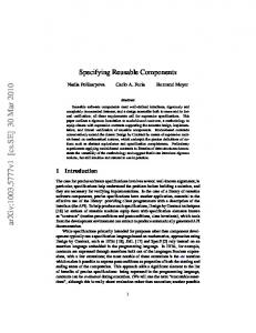
8 Experimental Results - Running on Different Platforms 8.1 System & Computing Architecture of Rocky 7 Rocky 7 is a Mars rover prototype that has six drive wheels with a rocker-bogey mobility mechanism. It has two steerable front wheels and four non-steerable back wheels. Mounted onto the rover platform are two manipulators: a two degree-of-freedom (DOF) arm with two independently actuated scoops, and a three degree-of-freedom mast. The arm has a shoulder roll and a shoulder pitch, while the mast has an additional elbow pitch. Three pairs of stereo cameras are mounted on the rover: a stereo camera pair is mounted on the mast, and two stereo camera pairs are mounted on the
sists of a 3U cPCI backplane with a 300 MHz Pentium processor with on-board Ethernet, two PX610 frame-grabbers, and a Sensoray digital I/O board. The main processor runs a VxWorks 5.3 real-time operating system. Each actuator (DC brushed) is controlled by a separate micro-controller (LM629) connected to the Sensoray board I/O board. The on-board processor communicates with an external host via a wired Ethernet at a maximum throughput of 10 MB/sec.
8.3 Implementation Results
Figure 6: The Rocky 7 rover
The Rocky 7 rover and the PDM mockup have different physical characteristics as well as different hardware implementations. Parts of the CLARAty Functional Layer has been implemented and tested on both systems. On the Rocky 7 rover, we were able to demonstrate parallel execution of arm, mast and mobility operations. We also demonstrate continuous driving and autonomous visionbased sample acquisition with parallel execution of the vision processing and the drive commanding. On the PDM mockup, we were able to demonstrate vision-based sample acquisition from a fixed platform sharing about 60% of the Functional Layer code. This percentage will increase as we further develop the generic framework. The proposed architecture was flexible, easy to use, and light-weight (memory and speed). Simultaneous multiple task operations were easy to invoke even when there are shared resources that needed to be resolved at high context switching speeds. For example, both systems used a shared 8 bit parallel bus to control their actuators). This resource was managed locally within the ControlledMotor class.
9 Future Work Figure 7: The PDM mockup rover front and back sides of the vehicle. The computing system consists of a 3U VME backplane with a 60 MHz 68060 processor with on-board Ethernet, two CX100 frame-grabbers, a VPAR10 digital I/O board, and a VADC20 analog I/O board. The main processor runs a VxWorks 5.3 real-time operating system. Each actuator (DC brushed) is controlled by a separate micro-controller (LM629) using an 8 bit parallel bus through the VPAR10. The on-board processor communicates with an external host via a wireless Ethernet.
8.2 System & Computing Architecture for PDM mockup The PDM mockup (see Figure 7) is a fixed manipulation platform with a 4-DOF arm and a 4-DOF mast mounted onto the platform. Both the mast and the arm have a similar joint configuration which include a shoulder roll, a shoulder pitch, an elbow pitch and a wrist pitch. The arm has a single DOF gripper while the mast has a stereo camera pair. The computing system is different than Rocky 7 and con-
We plan to continue the development of the Functional and Decision Layers of the CLARAty architecture. We will be implementing the interface between the two layers for the resource queries. We will also develop the various domains of the Functional Layer which include Input/Output, Motion Control, Mobility and Navigation, Manipulation, Perception and Vision, Resource Management, System Control, Communication, and Sensor and Instrument Processing packages.
10 Acknowledgments The work described in this paper was carried out at the Jet Propulsion Laboratory, California Institute of Technology, under a contract to the National Aeronautics and Space Administration.
References [1] R. Alami et al. An Archtecture for Autonomy. International Journal of Robotics Research, 17(4), April 1998.
[2] Ronald C. Arkin. Motor schema based mbilt robot navigation. Int’l Journal of Robotics Research, 4(8):92–112, 1989. [3] Matthew H. Austern. Generic Programming and the Stl: Using and Extending the C++ Standard Template Library. Addison-Wesley Professional Computing Series, Reading, MA, October 1998. [4] J. Borrelly et al. The ORCCAD Architecture. International Journal of Robotics Research, 17(4), April 1998. [5] Rodney A. Brooks. A robust layered control system for a mobile robot. IEEE Transactions on Robotics and Automation, 2(1):14–23, 1986. [6] Bruce Powel Douglass. Real-Time UML - Developing Efficient Objects for Embedded Systems. Addison-Wesley Longman, Inc., Reading, MA, December 1998. [7] Tara Estlin, Gregg Rabideau, Darren Mutz, and Steve Chien. Using continuous planning techniques to coordinate multiple rovers. In Proceedings of the IJCAI99 Workshop on Scheduling and Planning meet Real-time Monitoring in a Dynamic and Uncertain World, Stockholm, Sweden, August 1999. [8] R. Firby. Adaptive Execution in Complex Dynamic Worlds. PhD thesis, Yale University, Department of Computer Science, 1989. [9] Forest Fisher, Steve Chien, Leslie Paal, Emily Law, Nassar Golshan, and Michael Stockett. An automated deep space communications station. In Proceedings of the 1998 IEEE Aerospace Conference, Aspen, CO, March 1998. [10] E. Gat. On Three-Layer Architectures. In D. Kortenkamp, R. Bonnasso, and R. Murphy, editors, Artificial Intelligence and Mobile Robots, Boston, MA, 1998. MIT Press. [11] R. Knight, S. Chien, T. Starbird, K. Gostelow, and R. Keller. Integrating model-based artificial intelligence planning with procedural elaboration for onboard spacecraft. In Proceedings of Space Ops 2000, Toulouse, France, June 2000. [12] K. Konolige, K. Myers, E. Ruspini, and A. Saffiotti. The saphira architecture: A design for autonomy. Journal of Experimental and Theoretical Artificial Intelligence, 9(1):215– 235, 1997. [13] Maja J. Mataric. Behavior-based control: Examples forom navigation, learning, and group behavior. Journal of Experimental and Theoretical Artificial Intelligence, 2–3(9):232– 336, 1997. [14] I.A. Nesnas and M.M. Staniˇsi´c. A robotic software developed using object-oriented design. In ASME Design Automation Conference, Minnesota, 1994. [15] Lynn Parker. Alliance: An architecture for fualt tolerant multi-robot coorperation. In ORNL TM12920, Oak Ridge National Laboratory, Oak Ridge, TN, 1995. [16] G. Pardo-Castellote S. Schneider, V. Chen and H. Wang. Controlshell: A software architecture for complex electromechanical systems. Int’l Journal of Robotics Research, 17(4), April 1988. [17] R. Simmons and D. Apfelbaum. A Task Description Language for Robot Control. In IEEE/RSJ Intelligent Robotics and Systems Conference, Vancouver Canada, October 1998. [18] Reid Simmons and David Apfelbaum. A task description language for robot control. In Proceedings of the International Conference on Intelligent Robots and Systems, Vancouver, Canada, October 1998. [19] Mobility Software. http://isrobotics.com/rwi/software.htm. Real World Interface, a division of IRobot, Somerville, MA.
[20] R. Volpe, I. Nesnas, T. Estlin, D. Mutz, R. Petras, and H. Das. The claraty architecture for robotic autonomy. In Proceedings of the 2001 IEEE Aerospace Conference, Big Sky, Montana, March 2001.