work shows the limitations of typical methods for interaction design when applied ... The system has been growing from a location-based information system [14, 15] into a ... TIP is the redesign into a service-oriented architecture such that various ... Thus, the interaction design would stay within the abstraction concept that.
Towards a TIP 3.0 Service-Oriented Architecture: Interaction Design Annika Hinze, Petra Malik, Robi Malik Department of Computer Science, University of Waikato {hinze, petra, robi}@cs.waikato.ac.nz Abstract This paper describes our experience when applying formal methods in the design of the tourist information system TIP, which presents context-sensitive information to mobile users with small screen devices. The dynamics of this system are very complex and pose several challenges, firstly because of the sophisticated interaction of several applications on a small screen device and the user, and secondly because of the need for communication with highly asynchronous event-based information systems. UML sequence diagrams have been used to capture the requirements and possible interactions of the system. In a second step, a formal model has been created using discrete event systems, in order to thoroughly understand and analyse the dynamics of the system. By verifying general properties of the formal model, several conceptual difficulties have been revealed in very early stages of the design process, considerably speeding up the development. This work shows the limitations of typical methods for interaction design when applied to mobile systems using small screen devices and proposes an alternative approach using discrete event systems.
1 Introduction This paper focuses on the redesign of the mobile context-aware tourist information system TIP into a service-oriented architecture. In particular, this paper reports about the interaction design using discrete event modelling. Context of the TIP Project. We have been developing a mobile tourist information system that provides context-aware information delivery to the user (traveller). The system has been growing from a location-based information system [14, 15] into a mobile system supporting several different services [12, 13]. The next design step for TIP is the redesign into a service-oriented architecture such that various services are supported in a flexible way. Challenges of the Design. The complex interactions between the core system and the services together with the management of user context (such as location and interests) and the interplay with the mobile client device create several design challenges. Turning to existing literature for guidance for the redesign, we soon realized that typical design tools might not provide solutions for the challenges we were facing. We will discuss this aspect in Section 7. The challenges of the interaction design with focus on system-user interaction aspects have been discussed in [11]. 1
(a) Current location
(b) Map
(c) Recommendations
(d) Browse
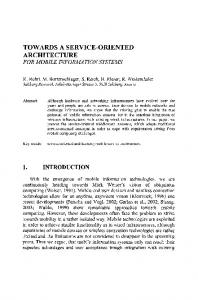
Figure 1: TIP in Use: Context-dependent information delivery; core system information delivery (see a), services (see b and c) and browsing interface (see d).
Contributions of this Paper. This paper describes the design process using automata for discrete event modelling [6, 24]. This approach seemed most appropriate and promising, as the internal control of the system is implemented using an event-based system. Thus, the interaction design would stay within the abstraction concept that guides the system’s internal logic. Structure of this Paper. Section 2 briefly describes details about the TIP system that are necessary for the purpose of this paper. Section 3 introduces the architecture of the TIP system and the basics of the service interactions. Section 4 illustrates the design of the interactions within and between the services using UML sequence diagrams. Section 5 introduces the interaction design by modelling interactions using automata for discrete event modelling. Section 6 discusses the lessons learnt regarding interaction design for mobile systems. We conclude the paper with a brief discussion of related work in Section 7, and a summary of our findings and future work in Section 8.
2 TIP Background TIP is a mobile system that delivers tourist information about sights (information objects) based on the user’s context: their location, two personal profiles describing interest in (semantic) sight groups and topics, and the user’s travel history. The system also considers the sights’ context, such as their location and memberships in semantic groups. Sights that are in a semantic group share certain features (e.g., medieval churches). In addition to this core functionality, TIP supports several services such as recommendations and a map service. Figure 1 shows the TIP core system and its services in use. In Figure 1(a), sightrelated information is delivered for the current location of the user. TIP also supports navigation by maps. The current location and the location of sights is dynamically indicated on the map. At the same location as before, the map shows the interface as given in Figure 1(b). The recommendation interface is depicted in Figure 1(c). For recommendations, we assume that a user who has seen several sights in a group is interested in seeing more. Recommendations are also given based on user feedback and profiles [13]. Users may also browse for other places; the interface indicates browsing with a different color scheme as seen in Figure 1(d).
2
The TIP system has an event-based infrastructure combined with a location-based service. The heart of the system is the filter engine cooperating with the location engine. The filter engine selects the appropriate information from the different source databases depending on user and sight context. Thus, the systems interaction logic is defined in context-aware profiles for the event-based filter engine. The system is implemented as a client-server architecture, supporting desktop clients as well as mobile clients on a hand-held device with appropriate interfaces.
3 Architecture and Service Interaction This section serves two purposes. Firstly, we describe the motivation for and idea of using a service-oriented architecture for TIP 3.0. Secondly, the basic interactions between the system components are explained.
3.1 Motivation for a Service-oriented Architecture As argued in the analysis of TIP 2.9 [12], an apparently simple final service provided to the user (e.g., a tourist guide with map, sight data and recommendations) is in fact a composition of a variety of services. Often, these services need to communicate together both within the same machine and between computers, using thick- and thinclient scenarios, and occasionally in hybrid approaches. Unlike a monolithic approach, often seen in existing mobile information systems, a modular, service-oriented approach allows for the exploration of alternatives, e.g., of communication or implementation. This is important where even fundamental services such as location can be provided in different ways, e.g., GPS or 3G wireless telephony. Furthermore, new services can add entirely new features to the framework without requiring the re-implementation of or changes to existing services. With TIP 2.9, we have successfully created a framework, in which mobile services cooperate. This can already be seen in the communication between the map and sight information services to provide sight location halos in the map. For TIP 3.0, further forms of cooperation and composition are needed. For example, we wish to extend the display module in the map system to support different halo cues (e.g., for sight type or recommendation), and this requires inter-process communications that may in turn require further development of our framework. With the trend of information systems moving onto mobile devices and using small screen interfaces, the aforementioned requirements will become more pronounced. Client devices will provide a number of pre-installed services and users will add their own selections. Consequently, we believe that for TIP 3.0 even stronger decoupling and modularisation is needed: a mobile infrastructure for mobile information services needs to flexibly support existing, changing or new services. The design of TIP 3.0, for which the interaction design is reported in this paper, will see the redesign of TIP into a Service-Oriented Architecture (SOA) using web services.
3.2 Basic Interaction Principles The current version 2.9 of TIP is a client/server system that is being extended to a hybrid client/server and peer-to-peer structure in TIP 3.0. Servers can be seen as special peers with access to more data and bandwidth. Here, we focus on the interactions of
3
user data user history sight data
maps
databases
Recommenation Service 1
Information Service
Recommendation Service 2
3 new_location(user)
4 new_sight(user, sights) Event−based middleware (ENS)
2 new_location(user)
5
new_sight(user, sights) Client Broker
1 new_location Location Service
2
6
6
new_sight(sights)
new_sight(sights)
new_location Map Service
Display Service (Browser)
get new location triggered by time triggered by distance trigered by user/button
Figure 2: TIP 3.0 architecture and interactions between services and components.
a mobile client with the server (and other peers as potential data sources). We abstract from the actual location of the data on different peers. In Figure 2, we illustrate the distributed nature of TIP’s services and components. The databases and basic services are held on the server side (Figure 2, top), each mobile client can have several services running; interaction between services on the mobile device are coordinated by the client broker (Figure 2, bottom). The middle layer is formed by an event-based communication middleware (Figure 2, centre). We abstract from details of the implementation on server side. Information about the functionality and interaction of services and data sources on the client side can be found in [12]. Figure 2 shows the basic interaction between the services; basic interactions are also shown in Figure 3. At this time, we only consider independent actions; interdependencies of communications and service calls are discussed in Sections 4 and 5. The location service sends the current location of this user. This may be triggered by time (e.g., send every minute) or by location (e.g., send if the user moved more than 500m) or by user interaction with the system interface (e.g., a button being pressed to retrieve the new location). In Step ①, the location information is sent to the client broker that coordinates all services on this mobile device. In Step ②, the client broker attaches the user’s ID and sends the information to the event-based middleware (ENS). The information is also sent to the map service that is running locally on the mobile device. Here, we abstract from the possible distribution of the ENS over the mobile clients and the server. The event-based middleware holds service registrations and profiles about the information need of each service. As a basic service offer, it sends the information about the user’s current location to the information service (and to all other services that requested this information). This is 4
Location Map Service Service Browser move
Client Broker
ENS
Information Sevice
Recommendation Service
new_location new_location new_location(user) new_location(user) new_location(user) new_sight(user,sight) new_sight(user,sight) new_sight(sight) new_sight(sight) new_rec(user,rec) new_rec(user,rec) new_rec(rec) new_rec(rec)
Figure 3: Basic interaction: User change of location. As the user moves, browser and map are updated with location, sights and recommended sights (shaded services are located on the middleware layer).
shown as Step ③. The event-profile logic that can be used for the ENS in this context has been introduced in [15]. The information service receives the user’s location (new_location) and the user ID; it looks up the sights nearest to the location that are of interest to the user. The functionality of the information service has been described in detail in [14]. As Step ④, the information service sends back to the ENS the list of sights that are close to the user (new_sight). The ENS forwards that information to the user’s mobile device (i.e., to the client broker); shown as Step ⑤. The client broker distributes the information to the local services as needed, in Step ⑥. In this case, the display service receives the list of sights and sight information; it will display this information to the user to chose the object in which they are interested. The recommendation service also receives the user’s location and the user ID in Step ③ (new_location). It looks up the sights that would be of interest to the user and which the user has not seen already. Recommendations may also use feedback of other users. The functionality of the recommendation services has been described in detail in [13]. As shown in Figure 3, the recommendation service sends a list of sights back to the ENS. This list is then forwarded to the client broker on the mobile device. The client broker distributes the information to all services that are interested, i.e., the display service (for profiling information about the sights) and the map service (for highlighting the recommended sights). Depending on user action (browsing behaviour on map or in other service) or information delivered to the service (location), the map service may request further maps.
4 Interaction Design in Sequence Diagrams Our first attempt at the design of the interactions was to describe the interplay of the services using UML sequence diagrams [17]. This section shows the resulting diagrams and explains the interactions between the services.
5
4.1 Basic Interactions We modelled the following activities (providing references to the figures showing the sequence diagrams). Location Map Service Service Browser
Client Broker
ENS
Information Sevice
Recommendation Service
select(sight) req_detail(sight) sight_selection(sight) req_detail(sight,user) req_detail(sight,user) new_detail(user,sight) new_detail(user,sight) new_detail(sight) feedback
expose_detail(sight) feedback(sight) feedback(sight, user) feedback(sight, user)
Figure 4: Select sight from the list for more information. Follows from Figure 3.
1. User change of location (sequence diagram in Figure 3). The user changes their location and, subsequently, browser and map are updated with location, sights and recommended sights. This interaction was described in detail in the previous section. 2. Select sight from the list for more information (sequence diagram in Figure 4). The user picks the sight they are looking at from the list of sights that are presented to them on the screen. They can give feedback about how they liked the sight. 3. Select sight from the map for more information (sequence diagram in Figure 5). The user picks the sight they are looking at from the map where the sights are indicated. The application switches over to the information interface when the information is available. Users can give feedback about how they liked the sight. Moving the mouse over the sight in the map without clicking could give some information (already downloaded in task in Figure 3). 4. Browse for sight information (sequence diagram in Figure 6). An example is the browsing for more information about recommended sights. The design in Figure 6 has the drawback that people can assign feedback to objects they did not visit. Another option would be to present a site with all objects visited and not rated and one with all objects visited to redo the ratings. To setup the system in the beginning, the design in Figure 6 would be better—you can rate sights you know, even though you did not have the system yet. 5. Select sight information for distant sights (sequence diagram in Figure 7). An example for this task is the selection of a particular (distant) sight on the map, e.g., a recommended sight. The design in Figure 7 has the same drawback as in Figure 6 that people can assign feedback to objects they did not visit. 6
Location Map Service Service Browser
Client Broker
ENS
Information Sevice
Recommendation Service
select(sight) req_detail(sight) highlight_sight sight_selection(sight) req_detail(sight,user) req_detail(sight,user) new_detail(sight,user) new_detail(sight,user) new_detail(sight) expose_detail(sight) feedback feedback(sight) feedback(sight, user) feedback(sight, user)
Figure 5: Select sight from the map for more information.
Location Map Service Service Browser
Client Broker
ENS
Information Sevice
Recommendation Service
select(sight) req_detail(sight,browse) sight_selection(sight, browse) req_detail(sight,user) req_detail(sight,user) new_detail(user,sight) new_detail(user,sight) new_detail(sight) expose_detail(sight,browse)
feedback
feedback(sight) feedback(sight, user) feedback(sight, user)
Figure 6: Browse for sight information, e.g., about recommended sights.
6. Browse for new locations on the map (sequence diagram in Figure 8). Note that zooming and moving of the map is equivalent to scrolling in a browser; all interaction stays within the service. Location browsing, as modelled here, is the equivalent of browsing on information pages (modelled in Task 5). A virtual user (i.e., a pointer set by the user) is placed onto a new location on the map to receive information about that place without having to be at that location.
4.2 Refined Interactions The modelling of the location transmission can be refined to capture different approaches. This opens new possibilities for the interaction design. 7. New Location transmission (sequence diagram in Figure 9). So far, we abstracted from the different modes of sending locations. As indicated in Figure 2, location is measured and transmitted constantly (we ignore the internal control of 7
Location Map Service Service Browser
Client Broker
ENS
Information Sevice
Recommendation Service
select(sight) req_detail(sight, browse) highlight_sight (browse) sight_selection(sight, browse) req_detail(sight,user) req_detail(sight,user) new_detail(user,sight) new_detail(user,sight) new_detail(sight, browse) feedback
expose_detail(sight, browse) feedback(sight) feedback(sight, user) feedback(sight, user)
Figure 7: Select (distant) sight information, e.g., about recommended sights, from the map.
the location signal, such as GPS). The transmission of the location information to other services depends on the mode. The information can be sent (a) continuously whenever the user moves, (b) depending on the time since the last reading, (c) depending on distance from the last reading, and (d) triggered by user action (e.g., button pressed). Hybrid forms are also conceivable and depend on the actual location service implementation (e.g., location signal is sent according to time frequency or if the distance crosses a threshold ). In fact, the system may have to behave differently for different services involved (see Task 9). Currently, TIP 2.9 supports the latter mode of requiring user interaction with the system. This mode leads to several irritating features for the user interaction, which we discuss in Section 6. Modelling the different modes using the sequence diagrams does not reveal their severe consequences for user interactions (such as a divergence between the screen location and the real location of the user without indication in the interface). 8. Basic interaction refined (sequence diagram in Figure 10). When the user moved, their representation (e.g., avatar or location-halo) in the map should move as well. This does not hold for the information delivered. We assume that new information is only shown when triggered by the user to avoid flickering of the display. Also, when information about a building is received, the user should be able to access this information while walking around the building. 9. Browsing by walking (sequence diagram in Figure 11). This action depends on the implementation of Task 7 (transmission of location data). Switching into a different mode, the users are able to browse through their environment (virtual and real) by walking. On their TIP screen, new locations and sights are continuouslly updated as they walk. Consequently, depending on the implementation of Task 7, the interaction mode has to change for both interfaces (map and browser) when switching into this particular behaviour. One possible sequence diagram is shown in Figure 11: location information is continuously sent; the interfaces are updated whenever new information is available; the information system display is only updated on request. This mode is not designed for reading and browsing 8
Location Map Service Service Browser new_location(browse)
Client Broker
ENS
Information Sevice
Recommendation Service
set_location_identifier_on_map(browse) new_location(browse) new_location (browse) new_location(user) new_location(user) new_location(user) new_sight(user,sight) new_sight(user,sight) new_sight(sight, browse) show(sight,browse) new_sight(sight, browse) new_rec(user,rec) new_rec(user,rec) new_rec(rec, browse) show(rec,browse) new_rec(rec, browse)
Figure 8: Browse for new locations on the map.
through content but for scanning the environment and discovery of new places. For further information, the user would switch back into the mode in Task 8.
4.3 Interface Interactions A few interactions with the system are designed for navigating on the screen and between the information given. These cannot be modelled satisfactorily using sequence diagrams since the different states of the interface are an important aspect that would no be available in these models. 10. Interaction: To current location (‘Synchronize’). On pressing this button, the user interface returns to the current location of the user on the map. The location is newly measured and sent to the system; that is the user and the system are synchronized. This button is helpful if the user was browsing though information or zooming and navigating on the map. 11. Interaction: To last location (‘Back’/‘Forward’). On pressing this button, the user interface returns to the last location that was measured, ignoring user moves in between. This gives the user the opportunity to return to the last information that was delivered before they started browsing and/or walking around. It also offers the option of moving through locations (backwards and forwards) instead of presented pages. 12. Interaction: Navigation ’Back’/’Forward’. On pressing this button, the user can browse through the pages that have previously been presented to them, or move forward from earlier pages. The metaphor is that of a web-browser but applied to a set of services. This navigation should work over all services (each service itself might provide their own navigation). A few implications can be drawn from the above modelling attempts. For example, the user interface should provide options for setting modes (trigger, browsing by walk-
9
Client Broker
distance triggerred
time−triggerred
continuous
Location Map Service Service Browser move
Information Sevice
ENS
Recommendation Service
new_location new_location new_location(user) new_location(user) new_location(user) move new_location only proceed if T>threshold (T=time between two moves)
new_location independent
new_location(user) new_location(user) new_location(user)
move new_location only proceed if D>threshold (D=distance between two locations)
new_location independent
new_location(user) new_location(user) new_location(user)
user triggerred
trigger new_location new_location new_location(user) new_location(user) new_location(user)
Figure 9: Different variations for location transmission.
Location Map Service Service Browser
Client Broker
ENS
Information Sevice
Recommendation Service
move new_location new_location
only proceed if D>threshold (D=distance between two locations)
independent trigger new_location(user) new_location(user) new_location(user) new_sight(user,sight) new_sight(user,sight) new_sight(sight) new_recommendation(user,rec) new_recommendation(user,rec) new_recommendation(rec) new_sight(sight) new_recommendation(rec)
Figure 10: Basic interaction refined: contiguous location update, information delivery only in trigger.
10
Location Map Service Service Browser
Client Broker
ENS
Information Sevice
Recommendation Service
switch mode to browsing_by_walking move new_location new_location independent
only proceed if D>threshold (D=distance between two locations) new_location(user) new_location(user) new_location(user)
new_sight(user,sight) new_sight(user,sight) new_sight(sight) new_sight(sight) new_rec(user,rec) new_rec(user,rec) new_rec(rec) new_rec(rec)
Figure 11: Browsing by walking.
ing). Also, several navigation options need to be provided for the interface (‘Back’, ‘Forward’) as well as for location (‘Synchronise’, ‘Back’ and ‘Forward’ to location).
5 Interaction Design Using Discrete Event Modelling While the message sequence diagrams developed in the previous section provide a good description of the requirements and possible usage scenarios of the TIP system, they cannot show the dynamics of the system behaviour and the complex interactions with the user interface. In contrast to modelling for an immobile desktop system, the small-screen interface on a mobile device considerably influences the system behaviour. Together with the necessary interactions with all the other services and the location-related aspects, this leads to very sophisticated concurrent interactions that need to be modelled carefully.
5.1 The Missing Link: Interfaces and States Douglas [10] distinguishes between simple, state, or continuous behaviour of objects in systems modelling. We identify the dynamic behaviour of the services in the TIP system as state-full. Therefore, finite-state machines are an appropriate technique to model these concurrent interactions. UML supports the modelling of finite-state machines with UML statecharts and UML activity diagrams [10, 22]. While UML statecharts have been used successfully to design reactive and real-time systems, there still is only limited tool support for the formal analysis of complex statecharts models. We strongly believe that, when modelling concurrent activities, the designer needs to be able to interact with the system to explore its capabilities and pitfalls. We therefore do not use UML statecharts, but a modelling tool for discrete event systems, which allows us to analyse the model for conflicts, and allows for interaction and playful exploration of the modelled system. The relationship between UML statecharts and discrete event systems, and a possible translation between the two formalisms is explored 11
in [20].
5.2 Principles of Discrete Event Modelling We use the VALID Toolset to model and analyse the behaviour of the TIP client. The VALID Toolset, developed at Siemens Corporate Technology, supports the modelling, verification, and code generation of finite-state automata as described in [3, 20]. It uses the modelling methodology of discrete event systems (DES) [6, 24]. In this framework, concurrent systems are modelled using several finite-state automata running in parallel. Each automaton is represented graphically as a state transition graph as shown in Figure 12. States are represented as nodes, with the initial state highlighted by a thick border, and terminal states coloured grey. Transitions are represented as labelled edges connecting the states: in Figure 12(c), e.g., the automaton map expose changes its state from hidden to exposed with an occurrence of the event map expose. If an edge is marked with more than one label, this indicates that any one of the corresponding events causes the transition. Automaton map expose in Figure 12(c), e.g., changes from state exposed to state hidden if a br expose or a map hide event occurs. If a certain state does not have any outgoing transitions labelled with a certain event, that event is disabled by the automaton and cannot occur in the system. For example, automaton map expose in Figure 12(c) disables event map expose when in state exposed . This rule applies only to events that occur somewhere in an automaton or, more precisely, to events that constitute the so-called event alphabet of the automaton. Events that do not occur in the event alphabet remain enabled and do not cause any state change of the automaton when they occur. For example, event map show(1) occurs in the event alphabet of map new[1] in Figure 12(b), but not in map expose in Figure 12(c). Therefore, automaton map expose is always ready to perform a transition with event map show(1), leaving its state unchanged. In this way, several automata are composed by synchronisation on common events. All synchronised automata repeatedly agree on an event to be executed next, and simultaneously perform the corresponding state transition. A state transition using an event σ can only take place if all synchronised automata that have σ in their event alphabet allow the event σ to occur. For more details on synchronous composition and other concepts from the theory of discrete event systems, please refer to [6,24]. The benefit of this very simple framework is that it does not only enable us to create and simulate a concise model of the dynamic system behaviour, but also makes it possible to use model checking [7]. This ability to check critical properties of the model quickly and automatically has helped us to discover several problems.
5.3 A Model of the TIP Client Using the VALID Toolset and the framework of discrete event systems, we have created a discrete event model of the TIP client and its interaction with the event-based middleware. Our model includes all the components constituting the TIP client on a mobile device as shown in Figure 2, namely the location service, the map service, the browser, and the client broker. It also includes a model of the behaviour of the event-based middleware (ENS), to the extent needed to capture the communication between the
12
br expose
map remove(1)
hidden
far
hidden
br expose cb new sight(1) map hide cb new rec(1)
map show(1)
map expose exposed
visible map select(1)
(a) map click[1]
near map show(1) cb new sight(1) cb new rec(1)
map map map map
(b) map new[1]
select(1) select(2) select(3) select location
(c) map expose
map select(2) map select(3) idle
idle map select(1) map req detail(1) map select(2) map select(3)
map select location map new location click
click map select(1)
(d) map req detail[1]
map select location
(e) map new location
Figure 12: The map model.
client and the ENS. The details of the information systems on the server side are not modelled. When modelling a system that includes large amounts of complex data, such as TIP, using discrete event systems, abstractions are necessary in order to guarantee that the state space remains finite. In a discrete event model, it usually is not possible to include details about the information attached to the various events that may occur— only the fact that a message is sent or received is modelled, in most cases completely abstracting away from the associated data. In some cases, a certain reference to the data is needed to retain an interesting aspect of possible interactions. In our model, we assume that there are three different Sights 1, 2, and 3 that can be displayed. This number guarantees a tractable model, and is completely sufficient to reveal conceptual problems in the design. For clarity of the model, we also used other small simplifications. In the following, we describe each of the service components separately. The next section explains the interplay of these components, and shows some of the results obtained from the formal analysis of the model. The Map Service. The map service shows the location of the user as well as sights and recommendations nearby. It is possible to click onto a sight or recommendation to get detailed information about it, which is then to be displayed in the browser. For the purpose of modelling the map service, sights and recommendations are treated alike, although they may be displayed differently on the screen. Figure 12 shows a simplified model of the map service, which only supports a single map with a fixed number of up to three sights or recommendations. Dynamic updates of the map area are not supported, nor is the removal of sight information, nor the highlighting of the sight shown in the browser. Since the model is restricted to three sights, the map can show none, one, two, or
13
three sights. Automaton map click[1] in Figure 12(a) models whether Sight 1 is shown on the map or not. There exist similar automata for Sights 2 and 3, which are not depicted in Figure 12 since the only difference is the sight number in brackets. Initially Sight 1 is not shown. Becoming visible is modelled by event map show(1), and becoming invisible is modelled by event map remove(1), both changing the state of automaton map click[1]. The automaton uses another event, map select(1), allowed when Sight 1 is visible, which does not change the state of the automaton. The important point here is that event map select(1) is only possible when Sight 1 is shown on the map; an obvious consequence of how users can interact with a mobile device. The map highlights known sights and makes them selectable for the user. Automaton map new[1] in Figure 12(b) models that Sight 1 is shown on the map after the map has received information about it as a sight (event cb new sight(1)) or as a recommendation (event cb new rec(1)) from the client broker. Again, there are similar automata for Sights 2 and 3 not depicted here. Also note that automata map new[1] and map click[1] synchronise on the common event map show(1), i.e, the event map show(1) is only possible if both automata are in a state where this event is allowed. There are more factors that influence whether it is possible to click at the map browser. The map can be either exposed, which means it is visible on the screen, or hidden, and thus not visible on the screen. The user is only able to click onto the map if it is exposed. This behaviour is modelled by automaton map expose in Figure 12(c). The automaton has two states: one representing the hidden map and one representing the exposed map. State changes are indicated by events map hide and map expose. Also, if the browser gets exposed, indicated by event br expose, the map becomes hidden if it was exposed. Automata map req detail[1] in Figure 12(d) and map new location in Figure 12(e) describe the behaviour of the map if the user clicks on it. The user can select sights displayed on the map to request for detailed information, or click elsewhere to explore other areas. After one or possibly more clicks on Sight 1, the map sends a map req detail(1) event to the client broker, requesting detailed information to be shown in the browser. The attempt to send this message is cancelled if the user clicks on another sight. Note that automaton map req detail[1] does not restrict the occurrence of map select events since they are allowed in all states of the automaton—it only observes their occurrences. If the user clicks on the map to browse to a different location (event map select location), a map new location event is sent to the client broker in order to start searching for sights and recommendations close to the selected location. The Browser. The browser is used to show textual information about sights visited by the user. In the model, it can display a list of sights close to the current position of the user, a list of recommendations close to the current position of the user, or the detailed information of a specific sight. It can display information in the form of web pages received from the client broker, and request detail information, if the user clicks on hyperlinks. The current model assumes an intelligent browser that can combine information from several messages and change the display accordingly. The model of the interaction of the browser with the user as well as with the client broker is given in Figure 13. When a sight or recommendation gets close enough, the browser receives a message from the client broker. This is modelled for Sight 1 in automaton br new rec[1] in
14
map expose
br br br br
hidden map expose br hide
far br expose
far
cb new rec(1)
idle br req detail(1) br select(2) br select(1) br select(3) br select rec list br select sight list
cb new sight(1)
exposed br br br br br
select(1) select(2) select(3) select rec list select sight list
(a) br expose
near
near br show rec(1) cb new rec(1)
(b) br new rec[1] (c) br new sight[1]
map expose cb new detail(1) cb new detail(2) cb new detail(3)
br expose cb new detail(1) cb new detail(2) requested map expose cb new detail(3) br hide br expose exposed cb new detail(1) cb new detail(2) cb new detail(3)
hidden
visible
br expose sight list br select(1)
requested br br br br
br expose detail(1) br select(2) br select(3) br select rec list br select sight list cb new detail(1) cb new detail(2) cb new detail(3)
expose expose expose expose
sight list detail(2) detail(3) rec list
exposed
(f) br expose sight[1] br select(1) br expose sight list sight list br expose detail(1) detail(1) br expose detail(2) detail(2) br expose detail(3) detail(3) other hidden br expose rec list
br br br br hidden
expose expose expose expose
br show rec(1)
br show sight(1) br show sight(1) br remove sight(1) br remove sight(1) rec list detail(1) detail(2) detail(3)
br select(2) br select(3) br select rec list br select sight list cb new detail(2) cb new detail(3)
cb new detail(1)
br expose sight list
expose expose expose expose
hidden
cb new detail(1)
br select(1) br expose rec list expose rec list br expose detail(1) expose detail(1) br expose detail(2) expose detail(2) br expose detail(3) expose detail(3) other hidden
br br br br
(d) br req detail[1]
br select(2) br select(3) br select rec list br select sight list br expose detail(2) br expose detail(3) br expose rec list br expose sight list cb new detail(2) cb new detail(3)
(e) br tofront br br br br
click br select(1)
br show sight(1) cb new sight(1)
hidden
select(2) select(3) select rec list select sight list
br remove rec(1)
other visible br select(1) br expose rec list br expose detail(1) br expose detail(2) br expose detail(3)
(g) br click sight[1]
br show rec(1)
br remove rec(1) br br br br
expose expose expose expose
sight list detail(1) detail(2) detail(3) other visible visible br select(1) br expose rec list br expose sight list br select(1) br expose detail(1) br expose detail(2) br expose detail(3)
(h) br click rec[1]
Figure 13: The browser model.
15
idle idle idle loc new location cb new sight(1) map new location ens new rec(user, 1) cb new rec(1) cb new location(user) ens new sight(user, 1) req
event ens new sight(user, 1)
loc new location map new location
(a) cb new location br req detail(2) br req detail(3) map req detail(2) map req detail(3) cb uncache(1)
(b) cb new sight[1]
br req detail(1) map req detail(1) noreq
event ens new rec(user, 1)
req br req detail(2) br req detail(3) map req detail(2) map req detail(3) cb new detail(1)
(c) cb new rec[1]
br req detail(1) unavailable map req detail(1) cb req detail(user, 1)
cb req detail(user, 1)
cb uncache(1) ens new detail(user, 1) cached
(d) cb new detail[1]
cb new detail(1)
(e) cb cache detail[1]
Figure 14: The client broker model.
Figure 13(b) and br new sight[1] in Figure 13(c), respectively. After receiving a cb new rec(1) or a cb new sight(1) event, the browser can update its sight or recommendation list, indicated by event br show rec(1) and br show sight(1), respectively. Similar to the map, the browser can be either exposed or hidden, and clicking on the browser is only possible if the browser is exposed, modelled by automaton br expose in Figure 13(a). Furthermore, it is only possible for the user to click on Sight or Recommendation 1 (event br select(1)) if Sight or Recommendation 1 is in a list that is currently shown in the browser. This is modelled by automata br click sight[1] in Figure 13(g) and br click rec[1] in Figure 13(h). Automaton br click sight[1] has four states which record whether Sight 1 is shown in the sight list or not, and whether the sight list is currently displayed in the browser or not. Clicking on this sight is possible if the sight list is shown and the sight is contained in the sight list. Alternatively, Sight 1 could be contained in the recommendation list and therefore could also be clicked when the sight list is not displayed. A similar behaviour is specified for the recommendation list in automaton br click rec[1]. If the user clicks on a hyperlink to request details about Recommendation or Sight 1 (event br select(1)), a br req detail(1) event is sent to the client broker unless the user clicks onto another recommendation or sight before that event could be sent. This is modelled in automaton br rec detail in Figure 13(d) and works like to processing of clicks on the map. The client broker responds to the br req detail(1) event by sending a cb new detail(1) event, providing a web page with detailed information about the sight. As soon as this message arrives, the browser is exposed (unless it is already, see automaton br tofront in Figure 13(e)), and the information about the sight is displayed (see automaton br expose sight in Figure 13(f)). The Client Broker. The client broker links the applications on the mobile device with the network and the event notification system (ENS) on the server side. It also has to coordinate the map display and browser to ensure that control is passed correctly between these two applications. In most cases, the client broker simply forwards events received from the applications to the ENS and vice versa. New location information events (loc new location) received from the client’s lo16
idle
idle
cb new location(user) ens notat(user, 1)
cb new location(user)
ens norec(user, 1) moved
moved ens at(user, 1)
ens rec(user, 1)
arrived
arrived idle
ens new sight(user, 1) sent cb new location(user)
(a) ens new sight[1]
ens new rec(user, 1) sent cb new location(user)
(b) ens new rec[1]
cb req detail(user, 1) ens new detail(user, 1) req
(c) ens new detail[1]
Figure 15: The ENS model.
cation server are forwarded to the ENS (see automaton cb new location in Figure 14(a). New sight events (event cb new sight(1)) received from the ENS are forwarded to the map service and to the browser (event ens new sight(user , 1); see automaton cb new sight in Figure 14(b)). The same behaviour is modelled for recommendations (see automaton cb new rec in Figure 14(c)). The client broker forwards requests for detailed sight information to the ENS and caches the answer it receives; see automata cb new detail in Figure 14(d) and cb cache detail in Figure 14(e). The browser or map can request detailed information about a sight by sending a br req detail(1) or map req detail(1) event, which causes the automaton cb new detail to enter state req. In this state, the client broker is ready to forward this request augmented with the user ID to the ENS (event cb req detail(user , 1)). This event is answered by the ENS by providing detailed information (event ens new detail(user , 1)) which is stored in the cache indicated by automaton cb cache detail changing into state cached . At this stage the client broker can send a cb new detail(1) event to the browser, which will display the detailed information. Automaton cb new detail furthermore ensures that only the latest request for details is processed. Automaton cb cache detail prevents cached detail information to be requested again. The two automata also allow entries to be removed from the cache (event cb uncache(1)), but only if they are not currently requested. The Server Side. The model of the server side states the assumption that all requests sent to the ENS are actually answered. Automaton ens new detail in Figure 15(c) shows that the information systems answer a request for detailed information in form of a cb req detail(user , 1) event by an ens new detail(user , 1) event, which is assumed to have the corresponding web page attached. Furthermore, the information servers respond to location changes of the user, signalled by cb new location(user ) events. If such an event occurs, the databases are searched for sights that are close to the new position. The result of the search is an internal choice modelled by the information system performing one of the events ens notat(user , 1) and ens at(user , 1). If Sight 1 is close enough (ens at(user , 1)), this information is sent as an ens new sight(user , 1) event to the client broker. Similar
17
ens new sight[1]
cb new sight[1]
map new[1]
br new sight[1]
(initial state) loc new location cb new location(user ) ens at(user , 1) ens new sight(user , 1) cb new sight(1) map show(1) br show sight(1)
cb new location
Table 1: Example trace corresponding to Figure 3.
idle req idle idle idle idle idle idle
idle idle moved arrived sent sent sent sent
idle idle idle idle event idle idle idle
far far far far far near near near
far far far far far near near near
automata are used for recommendations.
5.4 Analysing the Model Having created the model, it is possible to run simulations and check whether the model can perform the interactions specified by the sequence diagrams. For example, Table 1 shows the event sequence corresponding to the basic interactions following a location change as specified in Figure 3. When a location change occurs, the location server on the mobile device sends a loc new location event to the client broker. This event triggers the client broker’s automaton cb new location to send a cb new location(user ) event to the ENS. The ENS, in this case represented by automaton ens new sight, may now detect that the user is close to Sight 1 (event ens at(user , 1)) and respond by sending an ens new sight(user , 1) event. This in turn triggers automaton cb new sight, which forwards the event as cb new sight(1) to the map service and browser. The cb new sight(1) event simultaneously activates automaton map new in the map service and br new sight in the browser, which causes them to display the new sights by events map show(1) and br show sight(1), respectively. In the discrete event model, a single cb new sight(1) from the client triggers actions both by the map service and the browser. The same communication is modelled by two separate interactions in the message sequence diagram in Figure 3. The notion of the client broker sending a single event, without necessarily knowing the receivers, seems to capture the intended behaviour of the event-based middleware more accurately. In addition to simulating the possible behaviours of the model, it is possible to perform some formal analysis and check whether the model satisfies properties of interest. We have checked that the model is controllable [6, 24], i.e., that it is always ready to react to any possible events caused by user interactions or the information systems, and
18
br select(2) br select(3) br select rec list br select sight list br expose detail(2) br br expose detail(3) hidden br br expose rec list br br expose sight list br cb new detail(1) br select(1) br select(1) clicked
select(2) select(3) select rec list select sight list br select(2) br select(3) br select rec list br select sight list
br req detail(1) br select(1)
requested
cb new detail(1) br select(1) cb new detail(1)
received br expose detail(1)
br br br br
select(2) select(3) select rec list select sight list
br br br br
expose expose expose expose
sight list detail(2) detail(3) rec list
br select(1) br select(2) br select(3) br select rec list exposed br select sight list cb new detail(1)
Figure 16: Broken version of automaton br expose sight[1]. that it is nonblocking [6, 24], i.e., that it is free from deadlocks and livelocks. These checks did not succeed immediately. By repeatedly verifying properties, we discovered several problems in the model. Then we eliminated the problems and checked the model again until all critical properties could be checked. An earlier version of the model included the automaton in Figure 16. It represents an attempt at creating a smarter browser that tries to avoid showing sight details if they are not the last thing the user clicked on. The idea is that, if the user clicks a link to Sight 1 in the browser, the browser requests detailed information about this sight from the client broker. However, this request is cancelled if the user clicks on something else before processing can be completed. Formal analysis shows that this approach does not work. If we replace automata br req detail[1] in Figure 13(d) and br expose sight[1] in Figure 13(f) by the alternative in Figure 16, and make similar changes for Sights 2 and 3, the model contains a deadlock and therefore cannot be proven to be nonconflicting. When trying to verify this property, the VALID Toolset produces a counterexample that reveals a problem in the design. The problem occurs in the following sequence of events. The user clicks on a link to Sight 1 in the browser (event br select(1)), which causes the browser to send a request for details about Sight 1 to the client broker (event br req detail(1)). At this stage, br expose sight[1] in Figure 16 is in state requested and waits for the client broker to send detail information about Sight 1. But before this information arrives, the user may active the map (event map expose) and click on Sight 2 on the map (event map select(2)). As a result, the map server sends a request for details about Sight 2 to the client broker (event map req detail(2), see Figure 12(d)). This causes the client broker to cancel the request for details about Sight 1, and only to process the second request (see Figure 14(d)). As a result the browser will never receive information about Sight 1, i.e., the automaton in Figure 16 will never receive the cb new detail(1) event needed to leave state requested —a classical deadlock situation. The root of this problem is that the browser cannot accurately determine which is
19
the most recent request from the user. The browser only knows about user interactions with the browser, not with the map service. In consequence, the decision about the most recent request must be shared between the two applications. To overcome the problem, the model has been changed to the one presented in Figure 13, where the client broker determines which request is the most recent by checking the events received from the browser and map service. The browser merely displays all the detail pages received.
5.5 Current Limitations of the Model The current model does not yet support all the features we would wish the system to provide. The following list shows the restrictions of the current model. • The sight information is sent only once by the ENS. • Once a sight is shown in the map, it is never removed. • The model supports only browsing by walking. • The map does not highlight the sight shown in the browser. • ‘Back’ and ‘Forward’ buttons are not modelled yet.
6 Lessons Learnt Here, we describe the lessons learned in both aspects of (a) modelling a mobile locationbased system and (b) using discrete event systems.
6.1 Modelling a Mobile Location-Aware System A clear distinction is needed between the following three user identities. 1. The real-world user: This is the person using the system; they can change their location in the real world. This location is captured by the location service in the system and triggers various responses. 2. The virtual user: This is the representation of the real-world user within the system. Typically the virtual user follows the movements of the real world user. The virtual user can also be used to ‘visit’ places within the system on behalf of the user (e.g., by clicking on the map to explore places at a distance). It should be possible to move through the location history of the virtual and the real user (e.g., using user-defined location points). 3. The interacting user: Independent of the location of the user, the interface allows to select browser pages, pictures and maps. The interaction is controlled by the real-world user. It should be possible to move through the interaction history with the system (similar to the back and forward buttons on a browser). Several issues for the interaction representation to the user have been identified. The issues identified occur as an immediate consequence of the mobility and location awareness on the system. They are typical for this kind of system. The first one is mode confusion regarding the different users and places (e.g., location of the real user on the map while browsing with the virtual user). The user
20
interface has to address this issue in a clear and comprehensible manner. This is especially important for the navigation through interaction and location histories. On the other hand, the server has to address this issue as well. For example, for deciding whether to include a certain location into the user history or whether to allow the user to give feedback about a place. The second issue is the location capturing. Several types of location capturing are supported for mobile systems; all provide varying semantics of new-location data (e.g., location measured after a time interval or depending on movement). These different types influence how the system can react, and how location events should be handled. A related issue is that of user movement in interaction with location capturing. This may lead to confusion about the actual location of the real-world user.
6.2 Modelling Using Discrete Event Systems By describing the requirements formally, first using UML and later using finite-state automata, developers are forced to think carefully about the planned system. The activity of specifying and modelling on its own helps the developer to understand and clarify many aspects of the system to be constructed. We have also seen that UML message sequence diagrams are very useful to describe particular sequences of actions, but fail to reveal problems that occur when several such action sequences are running together at the same time. By constructing an abstract model of the behaviour of the system, it becomes possible to simulate the interaction between the various components, and gain a thorough understanding of the dynamics of the system. Finally, the ability to perform exhaustive simulation and analysis of the model makes it possible to gain thorough understanding of the model and discover subtle problems at this very early stage of design. Several issues with the proposed interaction protocols have been discovered and solved, which may otherwise have remained undetected until much later during the implementation of the system.
7 Discussion of Related Work We grouped the discussion of related work into four groups: System modelling and design, User and Interaction modelling, Design of location aware mobile systems, and A-posteriori usability studies. System Modelling and Design. Modelling of concurrent systems using modelling tools based on state machines have mainly found application for mission critical applications, often focusing on safety issues. Bolignano et. al. [2] identify the application of formal methods in practical application as the missing link between two communities. They point out that non-functional requirements such as quality, robustness, dependability, and security may lead to wider acceptance of formal methods for software design. Our goal of designing a location-aware mobile information system strongly touches the issues of quality, robustness and dependability (which are introduced by the two criteria of location and support of mobile small-screen devices), and thus seems to be the a good example to support their observation. Evaluating the issues of security and privacy for our system is on our list for future work tasks. An example of a design of mission-critical tasks is that of flight interface control [8], where Degani et. al. follow a similar approach to ours. They use machine 21
transition diagrams to describe the different states and transitions of autopilots under several modes and interactions with a user model. As in our model, system interactions can be simulated, analysed and proven for correctness. They also focus on the design of correct displays in the sense of buttons which may be pressed without ever leading to failure states. Their paper again points out problems that have been identified earlier and that also came up in our study: the problems of lack of mode awareness, mode confusion, and automation surprise. For the design of interaction and interfaces for virtual environments, CSP (Communicating Sequential Processes) has been used [26, 28]. CSP is an alternative modelling principle which we could have used for our system. CSP is related to our modelling approach, but typically lacks modelling environments that support active simulation. In CSP applications, the aspects of location-awareness and mobile users are rarely considered. In virtual environments (as the ones mentioned above), the mobility of the user’s avatar does not interfere with the location of the real user as is the case in our application. User and Interaction Modelling. HCI research has focused on the modelling of users and their interaction with a system. Blandford et. al. evaluated different programmable user modelling (PUM) strategies for user-centered criteria such as tractability and re-usability [1]. Within their schema of operational and abstract models, the one used here is an abstract functional model, with the main advantage of provability. In general, the focus of their work is different to ours; in their evaluations, interactions between system components are not considered, nor concurrence and synchronization problems. [27] proposes modelling push-button devices using Markov models; this approach is similar to ours but evaluates a different kind of application. Degani at al [9] address the problem of mode confusion. They use statecharts and modelling structures. Their findings will be of importance for the presentation part of the user interface design. For the functional design, their modelling does not go far enough, the problems of concurrency are not addressed. Similarly, location and user movements introduce additional challenges that can only to a limited extend be modelled in modes (for example, in the difference between browsing and movement). The problem of mode confusion has also been addressed using formal modelling methods [5,25]. These approaches chiefly address the awareness of the users of the different modes (focusing on opacity, complexity, incorrect mental model) and on safety (one of the typical application fields of formal methods). The focus of the cited works is different to ours; in their evaluations, interactions between system components are not considered, nor are concurrence and synchronisation problems. In addition, the issues of location and user movements introduce challenges that are not addressed. Design of Location-Aware Mobile Systems. Typical design and evaluation of mobile location aware guides uses methods from desk-bound computers (usability studies see [18]). Our approach cannot be assigned to either of the design categories of ‘user centered’ or ‘technology centered’ as defined in [4, 19]. Our approach is closer to the technology-centered design, as it was created with reflection to an existing prototype and using technology-driven service models; but we also use the input of usage scenarios and enactment of future scenarios. A solely scenario-based approach is followed in [21].
22
The typical user-centered approach is followed in [23]: questionnaires, interviews and discussion with potential users lead to the system design with subsequent usertesting of a functional prototype. Most of the identified problems are related to the icons presented on the screen; we see this as user-device issues and interface which only form one part of the issues addressed in our design process. The findings of this project underline the assumptions of our approach: that design for mobile hand-held devices needs to be distinct from the one for desktop machines and interaction elements (and even the interaction sequences, as we found in our study) need to be designed differently in order to prevent common usage mistakes. Another result is the necessity to easily restart or resume actions that have been interrupted. We addres this issue by the introduction of the home/location buttons that give the users easy access to their current state and previous states within the system interaction. Another attempt towards the same issue is the presentation of the same information on map and information browser. Thus, clicks in the information browser result in a changes of context or mode in the map, e.g., selected items are highlighted such that the current interaction context is presented to the user via several cues. The same task also addresses the issue of integration, which is much more fundamental in mobile application than in traditional desktop systems. In conclusion, our design addresses selected issues (interaction syntax, resuming tasks, integration) identified by Pousmann et al [23] in an a-priori manner. Early HCI considerations for location-aware applications are discussed in [4]; in our prototype and the redesign modelling process, we identify and address similar issues. A-posteriori Usability Studies. Usability and interaction issues of mobile locationbased systems have often been evaluated a-posteriori, that is after the implementation of the software. For interaction design, the focus lies on the interface design of small screen devices and user-device interactions. Interaction design that takes locationawareness and mobility into account are rare. In recent year, several usability studies for mobile guides have been performed, using lab experiments [16], usage observations, and longitudinal studies with interviews. Kjeldskov et. al. [18] point out that the special characteristics of tourist guides make the design and evaluation a challenging task: close relation to physical location and objects in immediate user surroundings as well as the ambulating user constantly changing physical location. In their comparison of four different approaches to usability study for mobile applications [18], they identify as critical usability issues related to the mapping from the use of the system in the real world, such as (1) representation of information and interaction between user and system depending on the surrounding environment, and (2) disparities in the relationship presented in the system and the context in which the user was situated. These are two of the issues that we also identified as critical in our design phase. Thus, critical issues typically identified in usability studies could be identified already in the design phase. Summary. Classical system modelling is concerned with concurrency issues, safety, and correctness. Mobility and location-awareness usually is not addressed directly. When addressing interaction design for mobile systems, typically only the aspects of user interaction are considered as this community mainly regards problems of interactions using small screen displays. As pointed out in [4], location aware mobile applications pose more challenges such as identity of locations, virtual/real-world confusion,
23
complex interactions with cooperating services on the same device. When designing mobile location-aware applications, scenario-based and prototype-based approaches prevail. Only a few publications have dealt with the modelling of location-aware systems. Most evaluations of that are done are a-posteriori usability studies.
8 Conclusions This paper presents the lessons learned during the redesign of a mobile location-aware system, using a combination of UML message sequence diagrams and discrete event systems. It proposes an improved service-oriented architecture and points out that different contexts need to be distinguished with great care in mobile location-aware systems, with implications not only for the user interface but also for the interaction protocols between the various services involved. The formal modelling approach has greatly improved the system design. By describing the requirements formally, developers are forced to think carefully about the planned system. The activity of specifying and modelling on its own helps to understand and clarify many aspects of the system to be constructed. We have seen that UML message sequence diagrams are very useful to describe particular sequences of actions, but fail to reveal problems that occur when several such action sequences are running together at the same time. Therefore, a finite-state automata model of the system has been created and analysed. The result is an abstract model of the behaviour of the system, which makes it possible to simulate the interaction between the various components and gain a thorough understanding of the dynamics of the system. Exhaustive simulation and analysis of the model allows for finding subtle problems at this very early stage of the design. Several issues with the proposed interaction protocols have been discovered and solved, which may otherwise have remained undetected until much later during the implementation of the system. The design is a still ongoing process. As a next step for the interaction design, we plan to address the following issues. 1. Inclusion of interactions with other mobile peers 2. Distribution of components of the system, e.g., the ENS and the client broker (Does the ENS reside in part on the client side and should it be integrated with the client broker?) 3. Details of the interaction protocols of of the ENS and client broker (profile forwarding or late identifications?) 4. Implementation details of the client broker (internal event based interactions?) 5. Implementation issues of thick and thin clients (where to hold context information, e.g., browse, for a service that only supports thin clients) For the overall system design, we plan to (1) support for more services to identify abstractions for a service oriented architecture; (2) include trust based information exchange; and (3) model different applications with different services but same base architecture. For the design process using discrete event systems, we plan to implement an interface simulation to allow for more direct user-interaction with the simulated system. 24
References [1] A. Blandford, R. Butterworth, and P. Curzon. Models of interactive systems: a case study on programmable user modelling. Int. J. Hum.-Comput. Stud., 60(2):149–200, 2004. [2] D. Bolignano, D. Le M´etayer, and C. Loiseaux. Formal methods in practice: the missing link. a perspective from the security area. In Modeling and Verification of Parallel Processes (MOVEP 2000), 2000. [3] B. A. Brandin, R. Malik, and P. Malik. Incremental verification and synthesis of discreteevent systems guided by counter-examples. IEEE Trans. Contr. Syst. Technol., 12(3):387– 401, May 2004. [4] P. Brown. Some lessons for location-aware applications. In Proc. 1st Workshop on HCI for Mobile Devices, pages 58–63, May 1998. [5] R. Butler, S. Miller, J. Potts, and V. no. A formal methods approach to the analysis of mode confusion. In AIAA/IEEE Digital Avionics Systems Conf., 1998. [6] C. G. Cassandras and S. Lafortune. Introduction to Discrete Event Systems. Kluwer, Sept. 1999. [7] E. M. Clarke, Jr., O. Grumberg, and D. A. Peled. Model Checking. MIT Press, 1999. [8] A. Degani, M. Heymann, G. Meyer, and M. Shafto. Some formal aspects of humanautomation interaction. Technical Report NASA/TM-2000-209600, NASA Ames Research Center, Moffett Field, CA, 2000. [9] A. Degani, M. Shafto, and A. Kirlik. Modes in human-machine systems: Constructs, representation, and classification. Int.J. Aviation Psychology, 9(1):125 —138, 1999. [10] B. P. Douglas. UML statecharts. Embedded Systems Programming, 12(1), Jan. 1999. [11] A. Hinze and G. Buchanan. Context-awareness in Mobile Tourist Information Systems: Challenges for User Interaction. In Proc. Workshop on Context in Mobile HCI, in conjunction with Mobile HCI, Sept. 2005. To appear. [12] A. Hinze and G. Buchanan. Cooperating Services in a Mobile Tourist Information System. In Proc. Conf. Cooperative Information Systems (CoopIS), Nov. 2005. To appear. [13] A. Hinze and S. Junmanee. Providing recommendations in a mobile tourist information system. In Information Systems Technology and its Applications, 4th Int.Conf. (ISTA 2005), May 2005. [14] A. Hinze, K. Loeffler, and A. Voisard. Contrasting object-relational and rdf modelling in a tourist information system. In Proc. 10th Australian World Wide Web Conf., July 2004. [15] A. Hinze and A. Voisard. Location- and time-based information delivery in tourism. In Advances in Spatial and Temporal Databases (SSTD 2003), volume 2750 of LNCS, July 2003. [16] G. Iacucci, J. Kela, and P. Pehkonen. Computational support to record and re-experience visits. Personal Ubiquitous Comput., 8(2):100–109, 2004. [17] S. Kent. Formal methods for distributed processing: a survey of object-oriented approaches, chapter The unified modeling language, pages 126–152. Cambridge University Press, New York, NY, USA, 2001. [18] J. Kjeldskov, C. Graham, S. Pedell, F. Vetere, S. Howard, S. Balbo, and J. Davies. Evaluating the usability of a mobile guide: The influence of location, participants and resources. Behaviour and Information Technology, 24(1):51–65, 2005. [19] J. Kjeldskov and S. Howard. Envisioning mobile information services: Combining userand technology-centered design. In Proc. Asia-Pacific Conf. Human-Computer Interaction (APCHI 2004), 2004.
25
[20] R. Malik and R. M¨uhlfeld. A case study in verification of UML statecharts: the PROFIsafe protocol. J. Universal Computer Science, 9(2):138–151, 2003. [21] S. F. Nagata, H. van Oostendorp, and M. A. Neerincx. Interaction design concepts for a mobile personal assistant. In Proc. conference on Dutch directions in HCI, 2004. [22] Object Management Group. Unified modelling language (UML), version 1.5, 2003. Available at http://www.omg.org. [23] Z. Pousman, G. Iachello, R. Fithian, J. Moghazy, and J. Stasko. Design iterations for a location-aware event planner. Personal Ubiquitous Comput., 8(2):117–125, 2004. [24] P. J. G. Ramadge and W. M. Wonham. The control of discrete event systems. Proc. IEEE, 77(1):81–98, Jan. 1989. [25] J. Rushby. Using model checking to help discover mode confusions and other automation surprises. Reliability Engineering and System Safety, 75(2):167–177, Feb. 2002. [26] S. Smith, T. Marsh, D. Duke, M. Harrison, and P. Wright. Modelling interaction in virtual environments. In Proc. UK-VRSIG ’98, Exeter, UK, 1998. [27] H. Thimbleby, P. Cairns, and M. Jones. Usability analysis with markov models. ACM Trans. Comput.-Hum. Interact., 8(2):99–132, 2001. [28] B. van Schooten, O. Donk, and J. Zwiers. Modelling interaction in virtual environments using process algebra. In Proc. 15th Twente Workshop on Language Technology, 1999.
26