projects; software process interface; project management. I. INTRODUCTION ..... terminology in the field of agile software development. TABLE I ..... [23] M. R. Thissen, J. M. Page, M. C. Bharathi, and T. L. Austin, âCommu- nication tools for ...
© IEEE. This is the author's version of the work. It is posted here by permission of IEEE for your personal use. Not for redistribution. The definitive version was published in the conference/workshop proceedings
Towards Artifact Models as Process Interfaces in Distributed Software Projects Marco Kuhrmann, Daniel M´endez Fern´andez, Matthias Gr¨ober Technische Universit¨at M¨unchen Faculty of Informatics, Software & Systems Engineering Garching, Germany {kuhrmann,mendezfe,groeber}@in.tum.de
Abstract—Much effort has been spent to investigate the organization of distributed teams and their collaboration patterns. It is, however, not fully understood to which extent and how agile software processes are feasible to support distributed software projects. Practices and challenges that arise from the demands for communication are often in scope of current research. Still, it remains unclear what is necessary to monitor a project and to track its progress from a management perspective. A solution is to monitor projects and their progress on basis of the current quality of the created artifacts according to a given reference model that defines the artifacts and their dependencies. In this paper, we present an artifact model for agile methods that results from of a systematic literature review. The contribution serves as an empirically grounded definition of process interfaces to coordinate projects and to define exchanged artifacts while abstracting from the diverse local software processes. Index Terms—agile methods; artifact model; distributed projects; software process interface; project management
I. I NTRODUCTION Software projects are often operated in a distributed setting. Such settings require the organization of, e.g. the collaboration between different teams, which are often subject to an individual organizational culture and an own (local) way of working, potentially alien to the standards of the other distributed teams [1]. The exchange of artifacts between the different teams is hereby an essential task including the exchange of requirements or architecture descriptions, or project planning and controlling data. As already known from co-located projects, the exchange of artifacts remains, at the same time, a challenging task, which requires a mature configuration management process to avoid confusion and misunderstandings. Typical symptoms of misunderstandings are the distribution and the handling of files in different versions, conflicts that are caused by incompatible file formats, or different notions of the structuring of artifacts, all potentially resulting in an inconsistent result structure. In a co-located setting, such risks can be mitigated by a direct, just-in-time communication within the team. In a multi-site project, a clear agreement regarding the artifacts, their structuring, and their dependencies obligatory for all team members becomes even more important, because informal, short and clarifying communication lines are often not possible [2], [3]. Since artifacts represent all (tentative) outcomes such as documents, specifications, models, code, binaries or entire
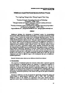
delivery packages, exchanging artifacts is critical to projects. However, a multi-site project setting does not only combine different sites (a site represents, e.g. a stakeholder, a company or an offshore team), but also local software processes used to create the artifacts. Those software processes do not necessarily have to be the same, which results in different concepts, a different terminology, and a different notion of the structuring of artifacts being created in a (sub-)project. This problem is inherently given in agile methods, such as Scrum, as they do not explicitly define an artifact model at all. In the following, we illustrate an example setting to motivate the need for a common notion of artifact models. Example Setting: To underpin the need for a common notion of artifacts and artifact models, we give a simplified example of a globally distributed project1 . Figure 1 shows a setting in which a project is operated in Europe, Asia, and South America, including offshoring, near shoring, and sub-contracting situations. The project’s coordinator is located in Germany and, therefore, the V-Modell XT was chosen as the basic software process. In Czech, Brazil, and India, Scrum is used for the development teams, and China, India’s sub-contractor, uses Extreme Programming. Although being a simplified example, several questions occur, such as: How can global requirements be transferred and mapped to local backlogs?, How can the global project plan be mapped to local fine grained project plans?, How can local project status information and controlling data be synthesized into a big picture reflecting the overall global project’s state?, and How can locally developed subsystems be integrated into a working software? Those exemplary questions show the challenges when combining different software processes. A way out of this dilemma is to abstract from concrete local software processes and to agree on a common artifact model as backbone of the different software processes. Such an artifact model would allow to specify the artifacts and the data to be exchanged while giving the possibility to integrate those artifacts into the different software processes used at different sites over pre-defined interfaces. 1 This example is based on a project in which client and contractor used different software processes, and the V-Modell XT was used to connect both projects. The experiences from this project [4] show the need for adequate techniques to couple projects using different software processes. For the purpose of the paper at hands, we extended the setting to a global one.
© IEEE. This is the author's version of the work. It is posted here by permission of IEEE for your personal use. Not for redistribution. The definitive version was published in the conference/workshop proceedings
Project Plan transfer & mapping Architecture Requirements Specification Backlog transfer & mapping
Coordination V-Modell XT
contract
System, Code, ... contract
Germany
Controlling Data XP contract
Scrum
Backlog Brazil Scrum
Controlling Data
Czech Project Controlling System, Code, ...
System, Code, ...
Controlling Data
China
India contract Scrum Controlling Data System, Code, ...
Fig. 1. Exemplary distributed project setting. The setting shows off- and near shoring, and contractor/sub-contractor configurations with different software processes that need to be integrated into one (virtual) project. The setting also shows some exemplary data and information flows that outline the challenges of transferring, exchanging, mapping, and aggregating data across project borders.
A. Problem Statement Although the importance of an artifact model as a means to define clear process interfaces for supporting management tasks among distributed projects is evident, little is yet known about which basic concepts should be incorporated by such a model. To avoid the pitfall of having a specific-purpose model, the model needs to capture the least common denominator of available software processes, especially mixing structured processes and agile methods—at the same time, without getting lost in abstraction. To support the actionability and reliability of the model in the sense of objectively reflecting common practices, it needs to be empirically grounded on basis of available and successfully disseminated practices. So far, apart from few experiences we could made in fundamental and applied research on artifact orientation (see, e.g. [4]–[7]), there exists no empirical basis that would allow to define a model of the necessary artifact types adequately reflecting the least common denominator of different software processes. B. Research Objectives We aim at defining a first artifact model and its process interfaces to lay the foundation of the necessary artifact types that adequately reflect the least common denominator of different software processes. To establish such a basis, we need to infer an artifact model from a literature study that reveals artifacts and their dependencies as they are successfully used and documented, extend the artifact model with software process interfaces (short: process interface) and provide a first validation of those interfaces. In our understanding, a process interface is a mean to exchange data between software processes or sub-processes by abstracting from concrete, organization- or project-specific implementations. To this end, a process interface shall serve
the standardized exchange of artifacts and further relevant information, e.g. planing or controlling data, between projects without the need to have deep knowledge about the respective project-internal workflows. C. Contribution In this paper, we contribute an artifact model for agile methods, which is based on a systematic literature review. For this empirically grounded artifact model for agile methods, we design and propose a generic extension as a software process interface to support distributed software projects by systematizing their data exchange. Furthermore, we provide a first validation of the model’s feasibility, which is based on a mapping of our artifact model to further ones including standard software processes we have implemented and disseminated into practice. D. Outline The paper is organized as follows. In Sect. II, we introduce the fundamentals and related work. In Sect. III, we give a brief overview of the mapping study we conducted to empirically investigate which artifacts are defined in available agile methods to infer an artifact model for agile methods. In Sect. III-D, we define artifact-based process interfaces. To this end, we generalize the agile artifact model, i.e. we revise the artifact model taking into account further available models and propose process interfaces as an extension of our artifact model. A first validation of our contribution is presented in Sect. V. In Section VI, we finally conclude our paper and discuss future work. II. F UNDAMENTALS & R ELATED W ORK To couple software projects that are operated using different software processes, necessary are modularization concepts in-
© IEEE. This is the author's version of the work. It is posted here by permission of IEEE for your personal use. Not for redistribution. The definitive version was published in the conference/workshop proceedings
cluding the support to customize and scale software processes and to replace (sub-)processes, and concepts that support the definition of a process-based interface to determine artifact structures that serve a coordinated data exchange. Much effort has been spent in defining modularity concepts for software processes, i.e. using modularization concepts to customize and tailor software processes at organization and project levels. Basic ideas to modularize, to compose and to connect (different) software processes arose in the mid 1980’s by realizing the need to tailor software processes, e.g. [8]. In subsequent years, a number of approaches to tailor software processes was developed. Pedreira et al. [9] conducted a study on the state-of-the-art in software process tailoring and concluded that there is no common framework for tailoring available and, furthermore, the impacts on projects when selecting certain tailoring criteria remain unclear [10]. A promising approach to enhance software processes’s modularity is given by another response to the problems mentioned by Basili et al. Brinkkemper [11] presented an approach for the situation-related engineering of software methods, which was baptized as Situational Method Engineering and, furthermore, initiated research on modular software processes. However, research on Situational Method Engineering remained on a conceptual level [12], [13]. From a practical perspective, software process metamodels, such as the Software & Systems Process Engineering Metamodel Specification (SPEM; [14]) provide concepts to modularize a software process. SPEM proposes several modularization concepts that compete for the process engineers’ favor, e.g. “process components” or “method plug-ins”. A SPEM process component is a means to compose reusable and exchangeable process assets, which are based on related tasks/activities and artifacts that provide a process interface. Ruiz-Rube et al. [15] conducted a comprehensive mapping study on the use of SPEM and concluded that SPEM gained much attention over the years. However, we conducted a literature review [16] in which we investigated the state-ofthe-art in software process meta-modeling, and concluded that currently we cannot observe initiatives to improve or further develop software process metamodels. Moreover, we have to recognize that initiatives, such as techniques given by Situational Method Engineering research, remain without any practical application, e.g. the software process metamodel ISO 24744 [17] has no practically relevant implementation yet. At the level of concrete software processes, we can find practically implemented process interfaces. For instance, the German V-Modell XT implements a so-called “customercontractor-interface” (CC-interface; [4], [18]) in which, based on contracts, the interaction patterns of different project stakeholders are modeled. The CC-interface comprehends a number of quality gates to which certain artifacts are assigned. Each artifact that is assigned to a particular quality gate is welldefined in structure, as it forms a part of a comprehensive artifact model, and it is subject to project management and quality assurance processes. Therefore, the interface describes the exchange of quality-assured artifacts among (sub-)projects.
The feasibility of applying an artifact-oriented approach in a project to enhance the clearness of artifacts was also investigated in several industrial settings, e.g. [6], [7]. Those findings underpin a proposed generalization of artifact orientation in terms of being a means to systematically model project result structures. However, modularity concepts as defined in, e.g. SPEM or in the field of Situational Method Engineering, aim at creating software processes—or parts of a software process— by assembling prefabricated building blocks. Agile methods gained much attention over the years and are well researched, e.g. in distributed settings [19], [20] including empirical studies [21]. Hersleb and Mockus [22] investigated collaboration and communication patterns in distributed projects in general, whereby communication is a basic pillar of agile methods, which is hard to realize in distributed settings and, thus, often relies on tools [23]. Since tools need “data” to exchange, artifact models that precisely describe outcomes, which themselves are a means for communication, proved to be advantageous [18], even agile methods usually neither have a notion of artifact orientation nor underlying artifact models. A number of studies shows the feasibility of applying concrete artifact models in industrial settings, and the application of artifact models evidently provides significant improvements, e.g. in the field of requirements engineering [7]. Yet, artifact orientation is a philosophy with various interpretations and manifestations in practice that needs further investigation [24]. Our contribution thus forms a next step in this direction. III. A RTIFACTS IN AGILE M ETHODS – A N E MPIRICAL I NVESTIGATION The term artifact is used in different contexts with different meanings. Our notion of an artifact and artifact models is defined in [5] where we contributed a metamodel for artifact orientation describing the basic constructs and rules. To investigate the state-of-the-art in the practical application of artifacts and artifact models in context of agile methods, we conducted a systematic literature review (SLR). The findings of this SLR result in an artifact model as it is used and documented in agile methods. In this section, we briefly present the core results from this study to lay the basis for the proposed general artifact model. The complete study can be taken from [25]. A. The Study at a Glance The overall goal of the study was to investigate the stateof-the-art of using artifacts in agile methods. To this end, we formulated the following research questions: RQ 1: Which agile methods and practices consider artifacts to which extend? RQ 2: Which degree of maturity have the agile methods, practices, and their artifact-oriented concepts w.r.t. their research type facet? The first two research questions aim at investigating the maturity of agile methods when it comes to defining and applying artifacts in projects. Those questions are designed
© IEEE. This is the author's version of the work. It is posted here by permission of IEEE for your personal use. Not for redistribution. The definitive version was published in the conference/workshop proceedings
FDD"
1"
1"
15"
5"
0"
b1"u rn
2"
6"
;d o
c3"od rt"
1"
3"
1"
1"
c2"od e" wn "ch a
1"
1"
d is fe ing 4"ocum 5"ature 6"sue" "sta en " t aE nd on ard " "
AUP"
1"
1"
2"
Kanban"
1"
3"
4"
i7" ter aE
2"
on
6"
2"
1"
1"
1"
1"
2"
3"
10"
2"
15"
1"
9"
3"
re ph pro u u m re so w ta te 8"eta 9" oto 10" du 11"leas 12"quir 13"Kwa 14"sk" 15"st"ca 16"se"ca 17"ser"st 18"all" ph " e"p ct"b em se" ory se" re" or" "b a l e s a a " yst nts n" ckl ckl em " og" og" "
5"
XP"
2"
Scrum"
wik 19" i"
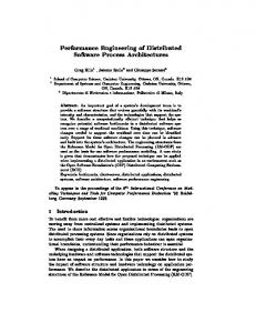
Fig. 2. Identified artifacts by method (consolidated view).
for a quantitative investigation and aim at harvesting different methods that consider artifacts in general. To answer the research questions, we performed a mapping study (see Peterson et al. [26]) to structure the publication flora and to determine the maturity of agile methods according to a predefined set of research type facets.
TABLE I S UB - QUERIES AND FINAL SEARCH STRING . Id
Search String
S1
RQ 3: Which artifacts are proposed for agile development and could contribute to cross-process and cross-practice artifact model?
S3
This research questions aims at investigating which artifacts are mentioned in agile methods and how those artifacts can be used to lay the foundation for a common artifact model. The research question contains two sub-questions: (a) Which of the proposed artifacts are commonly used? (b) Which of the proposed artifacts are used to serve project controlling?
S4 S5
(artifact or artefact or work item or work product or work result or deliverable or manufacture) (scrum or extreme programming or kanban or feature driven development or agile unified process) (stand up or (iteration or sprint) plan or test driven or unit test or burn down or retrospective or continuous integration or (velocity or sustainable pace) or coding standard or refactoring or collective ownership) (agile or agility or light weight) and (software) (software and (development or engineering))
SQ1 SQ2 SQ3 SQ4
S2 and S1 S3 and S1 S4 and S1 (controlling or measuring or reporting) and S5 and S1
Final
SQ1 or SQ2 or SQ3 or SQ4
S2
RQ 4: How are the common artifacts related to each other and what model does result from these relationships? Based on RQ 3, this research questions aims at identifying certain artifacts and relationships between the artifacts. Therefore, the outcomes of RQ 3 are revised and checked for synonyms to develop a clear terminology. Based on the results of an in-depth literature review, an empirically grounded artifact model was extracted that reflects the artifact structure as used in agile methods—backed up by the result set of the literature review. B. Research Method and Analysis Procedures To gather the data, we selected the following libraries: ACM Digital Library, IEEE Explore, SpringerLink, and Science Direct. Those databases were queried with the query strings from Table I, which were constructed using the most common terminology in the field of agile software development.
C. Results The search strings (Table I) were complemented by inclusion and exclusion criteria, which were applied in a rigorous selection procedure. The initial result set contained 540 contributions (books, conference and journal publications, etc.). After screening the initial result set and applying the inclusion and exclusion criteria, 76 contributions remained in the final result set for further investigation to answer the research questions (see [25] for more details). In this section, we present the results from the study. The presentation is structured according to the research questions. Due to space limitation, we only present the key results for the research questions 1–3. Since we aim at defining process interfaces that are based on artifact models, we present the findings of research question 4 in more detail.
© IEEE. This is the author's version of the work. It is posted here by permission of IEEE for your personal use. Not for redistribution. The definitive version was published in the conference/workshop proceedings
A5 Documentation
A10 Photo
A4 COTS Software
Project Management A3 Coding Standard
A19 Wiki
A9 Metaphor
visualizes
A1 Burn-Down
- final
Production Process
A12 Release plan
compliant to
«use»
visualizes
* - implement & tested by
A2 Code - final
- tests *
- implement
A6 Feature derives & influences itself
A17 User Story A16 Use Case
* - tested by
*
Requirements Specification
A15 Test case
- represented as *
- tests *
Backlog item
visualizes
contains
A11 Backlog
- priority - effort estimate contains
accumulates
A8 Iteration Backlog
A13 Requirement - description
A18 Wall
* - influences
- implements *
A14 Task A7 Issue/Bug
refines Backlog.contains
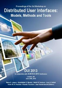
Fig. 3. Resulting artifact model for agile methods as outcome of the study.
1) RQ 1, RQ 2 & RQ 3: This first two research questions aim at structuring the publication flora via a mapping study. To this end, the selected 76 contributions were mapped according to their research type facets, and ordered by the publication date to get a notion of the development and the maturity of the considered domain. The outcome shows that the area of agile methods is well-researched: opinion papers and solution proposals are followed by evaluation (20 contributions) and validation research (15 contributions), and experience papers (20 contributions). The third research questions aims at identifying artifacts used in agile methods in general. To answer the research question, we analyzed all contributions w.r.t. artifacts that were explicitly named and/or used. Since the analysis resulted in a number of artifacts, we checked for synonyms and replacement candidates in the result set. Based on the result set, five agile methods, their notion and usage of artifacts were investigated. Figure 2 shows the consolidated list of the 19 identified artifacts and their distribution over different agile methods. The map shows XP and Scrum to contribute most of the identified artifacts while FDD does not contribute any artifacts at all. Furthermore, the map shows that XP pays more attention to development-related artifacts while Scrum also contributes to management-related artifacts. 2) RQ 4: Research question 4 aims at putting the pieces together and to infer a common artifact model for agile methods. To answer this research question, we analyzed the contributions to determine relationships between the identified artifacts and mapped the identified relationships to the consolidated set of artifacts (Sect. III-C1). The outcome is shown in Fig. 3. The artifact model consists of four parts:
1) Project management 2) Requirements specification 3) Production process 4) Other documentation parts, e.g. COTS software The figure does not only show all identified artifacts, but also an newly introduced artifact Backlog Item, which we introduced to simplify the set of dependencies. As the artifacts A10 Photo and A19 Wiki were mentioned in the contributions without any relationship to the other artifacts, we included those artifacts without further assignments to other artifacts. All artifacts together build a project’s documentation (artifact A5) and, thus, no explicit artifact named “Documentation” was placed in the model. The relationships in Fig. 3 are named according to the described relations between the artifacts as they are mentioned in the analyzed contributions. As a first step, the relations were investigated using a dependency matrix, before we generalized the dependencies and deduced a set of relationships. D. Discussion of the Study Results The results provide a first step in the definition of an artifact model for agile methods. The model still needs further synthesis and a clear structuring to reduce the complexity, introduce generalizations, and so on. At the same time, the model represents the state-of-the-art in agile methods and the artifacts and dependencies as they are implicitly or explicitly defined in those methods and documented in scientific literature. However, the result set from the SLR does not contain socalled “grey literature”, e.g. web blogs or forum contributions that are extensively used in the agile community and which has to be considered to be a threat to validity [25]. Therefore, from an academic perspective, our artifact model represents
© IEEE. This is the author's version of the work. It is posted here by permission of IEEE for your personal use. Not for redistribution. The definitive version was published in the conference/workshop proceedings
the least common denominator of the analyzed agile methods. To support the application of this artifact model in various software process models, we provide a synthesis and introduce an artifact-based process interface in the next section. IV. A RTIFACT- BASED P ROCESS I NTERFACES In the previous section, we presented an artifact model for agile methods as an outcome of a systematic literature review. The investigated artifact model represents common artifacts and their relationships, and their usage in context of agile methods. Since we also analyzed the contributions for their research type facets to get a first impression of their degree of maturity, we see the investigated artifact model to also represent a common foundation to build artifact models for agile methods. In this section, we further analyze the artifact model and extend it to a more generic model, which we use to abstract from local, project-specific processes. We consider the resulting artifact model to be an important part of a software process interface for distributed development projects. A. Crafting the Generalized Artifact Model Based on our study’s results [25], we investigated previously created artifact models to gather further information for creating a generalized notion of possible result structures in agile methods. To this end, we applied the following approach: 1) We performed another in-depth analysis of the outcomes of the introduced study [25]. As a result of the indepth analysis, we revised the resulting artifacts and their dependencies in order to create a (more) clearly structured and reusable artifact model. In this in-depth analysis, we furthermore identified gaps in the artifact model that could influence a data exchange. 2) We enriched the artifacts with previously gathered information from academic research cooperations, e.g. [5]– [7]. To this end, we introduced further artifacts that were identified in cooperation projects, and added attributes and relationships. 3) We introduced an abstraction layer to create the process interface. To this end, we used a generalization-based approach to refine process- or project-specific artifacts from the interface-related ones, e.g. for the artifact BacklogItem, which is defined in the process interface, a process/project-specific representative ProjectBacklogItem was introduced. In this step, we also classified the artifacts either to be part of the process interface or the process/project-specific parts of the artifact model. 4) We performed a first validation of whether the resulting structure serves the connection of distributed software projects (see also Sect. V). In this validation, we constructed exemplary cases in which we theoretically applied the process interface. B. A Generalized Artifact Model Figure 4 shows the resulting artifact model. The artifact model contains artifacts that result from the study (highlighted
by the stereotype StudyArtifact) as well as newly introduced ones that reflect the demands of, e.g. distributed industrial settings or software processes (see also the scenario provided in Sect. I). The proposed artifact model consist of three major parts: (1) the agile artifacts that are commonly used in agile methods, (2) tool support that is required for agile methods and which use is documented in literature, and (3) the process interface that serves the connection of projects and the data exchange between projects. 1) Agile Artifacts: The agile artifact model is an abstraction of artifacts, which we identified to be commonly used in agile methods [25]. These artifacts, including Feature, UseCase or TestCase, mainly address development-related topics, e.g. requirements engineering or development. Few artifacts address the project management, e.g. the Backlog or the Iteration Backlog. In addition to the artifacts revealed by the study, we introduced further artifacts to provide a consistent model. For instance, we decided to shift the artifact Code into the process interface and to replace it by a local representative (SourceCode) that provides more structure in terms of introducing resources, code modules etc. All artifacts that can be found in this package are usually specific to a particular team, e.g. a team could decide to use “formal” specifications instead of user stories. As long as the requirements of the process interface are fulfilled, the concrete materialization of an artifact does not matter. 2) Tool Support: Software projects in general and distributed projects in particular require an adequate tool support, e.g. for storing and sharing data, for communication, for development/coding or testing; project artifacts are, to a large extend, created and exchanged using certain tools (see also Portillo-Rodr´ıguez et al. [27]). In order to pay attention to project tools and their relationship to the project artifacts, we introduced the classes CollaborationTool and SCM-System (Source Control Management System; as an abstraction of, e.g. Subversion or git) for abstracting tools that serve distributed projects. The artifact CollaborationTool, furthermore, serves as container to store non-source code artifacts such as photos or several kinds of documentation. 3) Process Interface: The process interface contains those artifacts, which are relevant for exchange between projects. Due to their generic nature and their overall importance for software projects in general, four of the initially investigated artifacts (Metaphor, Requirement, BacklogItem, and Code) were located in the process interface. For instance, a requirement is—in a distributed project—relevant for at least three stakeholders: 1) The client—he constitutes the requirement 2) The implementation project—it “consumes” and implements the requirement 3) The integration project that puts all pieces of all subprojects together into a shippable software Further classes are present in the interface, which we describe in detail in Sect. IV-C.
© IEEE. This is the author's version of the work. It is posted here by permission of IEEE for your personal use. Not for redistribution. The definitive version was published in the conference/workshop proceedings
Process Interface
Agile Artifacts
«StudyArtifact»
- scenarios
Metaphor
- statement_of_intent
1..*
- requirements 1..* «StudyArtifact»
«StudyArtifact»
Requirement
Artifact - id - state - title - description - version
0..*
- rationale - acceptance_criteria - priority
relates
0..* 0..* - responsible - contributes 0..*
- owner has roles
1 Role - name 0..*
1..*
1
1..*
«StudyArtifact»
- scenarios 1..*
«StudyArtifact»
UserStory
UseCase
influences
- stakeholders Teammember
Person
- name - profession
0..*
Feature
- scenarios 1..* Scenario
- actor
«StudyArtifact»
1
Backlog
- project-id
assigned to
«StudyArtifact»
IterationBacklog - items 0..* «StudyArtifact»
- items 0..*
reports status
«StudyArtifact»
ProjectBacklogItem
BacklogItem
Task
- estimate
«StudyArtifact»
1..* contains
BurnDownChart
assigns
Issue Bug
«StudyArtifact»
«StudyArtifact»
SourceCode
Code
complies to use
contains 0..* - ressources
CodingStandard «StudyArtifact»
COTSSoftware
Ressource - submodules 0..*
Plan influences
CodeModules
IterationPlan
Deliverable
Release
1..*
«StudyArtifact»
ReleasePlan
- releases AcceptanceTest IntegrationTest UnitTest
Test
- cases 1..* «StudyArtifact»
ProjectTest
- preCondition - postCondition - testData - testResult
- cases 1..*
- subtests 0..*
TestCase
Tool Support shows
shows
«StudyArtifact»
Wall
CollaborationTool
SCMSystem
«StudyArtifact»
Documentation
«StudyArtifact»
Wiki
«StudyArtifact»
Photo
Fig. 4. Generalized artifact model for agile methods.
4) Discussion: Our initial study revealed a number of artifacts that are used in agile methods. However, a number of further artifacts had to be introduced to provide a meaningful artifact model2 . Such artifacts mainly serve the structuring aspects, e.g. the role of the class SourceCode that is a local representative of the interface class Code in a project, and aids the structuring of the code base by introducing modules. To separate “local” artifacts, which are created in a project, from the “global” artifacts, which are subject for inter-project or inter-team exchange, we introduced proxy-like classes, 2 This also reflects the situation that scientific contributions—obviously— only capture a part of the agile domain and, therefore, can at best serve as a basis for further investigations.
whereas each global interface class is complemented by a local representative. The local class inherits from the global class and, therefore, introduces the requirements regarding, e.g. the artifacts’ structure in a project. In tune with the philosophy of artifact orientation [5], the actual materialization of an artifact does not matter, as long as the inherited characteristics are fulfilled. C. Process Interfaces Based on the extended artifact model (Fig. 4), we define an artifact-based process interface as separately shown in Fig. 5. The central element of this model is the class Artifact. An artifact is, according to [5], a representation of all (tentative)
© IEEE. This is the author's version of the work. It is posted here by permission of IEEE for your personal use. Not for redistribution. The definitive version was published in the conference/workshop proceedings
«StudyArtifact»
Requirement
Test
- id - state - title - description - version
Metaphor
0..* - responsible - contributes 0..*
- preCondition - postCondition - testData - testResult
Deliverable
- statement_of_intent
0..*
Artifact
- rationale - acceptance_criteria - priority
«StudyArtifact»
relates
- owner has roles
1 Role
1..*
- name
1
1..*
- stakeholders
Person
- name - profession
0..* «StudyArtifact»
BacklogItem - estimate 1..*
«StudyArtifact»
contains
influences
Plan
Code
Fig. 5. The process interface based on an artifact model of artifacts in agile methods.
outcomes of a software project. An artifact has an id, a state, a version, a title and a description. Furthermore, an artifact has relations to other artifacts, to construct artifact models. In the context of distributed software development projects, we additionally define an artifact to be a subject to data exchange as part of a collaboration. Since distributed projects heavily rely on supporting collaboration tools [27], we understand an artifact to be a “data point” in such a tool infrastructure, which is exchanged across different teams or different sites. The interface in Fig. 5 addresses the aforementioned needs by defining a data structure in which Artifact is the base class for every piece of data to be exchanged among projects. In order to support the coordination of distributed projects, only few concrete key artifacts need to be exchanged to enable the project management to track a project’s state and progress. These concrete artifacts are: • Requirements • Code • Tests • Deliverables (e.g. the ones of sub-projects) • Planning and controlling information (general: plan, finegrained: backlog items) Furthermore, projects need personnel (assigned to roles). To this end, a minimum of personnel-related information needs to be transferred across project borders, e.g. to perform task assignments for bug fixing. Another artifact that should be a subject to exchange is the Metaphor as this artifact represents the shared vision of a project. Please note that the model in Fig. 5 is intentionally kept to a minimum of concepts to reduce the complexity as concrete artifact models for software processes or single projects are usually inherently complex themselves. Therefore, the proposed process interface serves as a minimal basis to allow for data exchange while the concrete, complex artifact models are defined, e.g. in a sub-project. The proposed interface is thus
an abstraction layer, which hides the local artifact models and, thus, the local software processes. V. I NITIAL VALIDATION Although the artifact model and the included artifact-based process interface presented in the foregoing section are the first steps towards an empirically grounded connection of software processes, we need further empirical investigations in different socio-economic contexts to test the sensitivity of our contribution to organizational demands and cultures. So far, however, we can provide a first validation to test the feasibility of our contribution when applying it in different—to some extent—theoretical contexts. This validation is steered by the following validation question that serves as our leitmotif. Validation Question: Does the artifact model represent a meaningful process interface? To investigate whether the introduced artifact model represents a meaningful process interface, we consider three cases, which we briefly discuss in the following. Those cases are chosen according to the scenario which we introduced in Sect. I. 1) General Support for Agile Methods (Bootstrapping): One main area of application considered important is the application of our artifact model in context of agile methods. Since the generalized artifact model is based on an empirical investigation of artifacts in agile methods, the proposed artifact model supports per construction agile methods. Terminology as well as contained classes reflect agile methods and practices [25]. Consequently, the proposed artifact model can lay the foundation to create concrete artifact models for particular projects, and abstract from a concrete methodology, which is applied in a project. Therefore, the proposed process interface provides a generic perspective to abstract from, e.g. concrete agile practices [28] selected on a project-to-project basis.
© IEEE. This is the author's version of the work. It is posted here by permission of IEEE for your personal use. Not for redistribution. The definitive version was published in the conference/workshop proceedings
Iteration scheduled
i
Delivery...
Project Plan Requirements ...
V-Modell Layer
Site 1
i
(controlling)
Report Document
Scrum Layer
Contract awarded
i
Site 2
2) Support for Artifact Models in Requirements Engineering (Practical Application): Independent of the a chosen process, especially distributed complex projects need to rely on well-founded requirements. Over the last years, we developed a series of artifact-based Requirements Engineering (RE) approaches covering different domains of applications. Those approaches were developed in research cooperations with, e.g. Capgemini Technology Services and became, after the process integration into their company-wide software process definition, the standard for RE (see, e.g. [7]). Taking into account that all of our RE approaches have their commonalities in high-level requirements (e.g. business goals or a system vision) that correspond to the Metaphor and an abstract class Requirement (in turn, specialized to further elements such as service or use case—depending on the application domain for which the approach has been developed), we can easily map the process interface with existing RE models. Furthermore, the artifact-based RE approaches developed at our research group can all be considered as an instantiation of our metamodel for artifact orientation including artifacts, tasks, and roles [5]. Thus, none of the elements provided by the interface remains unused whereby we consider our artifact model as a suitable process interface to be applied in artifactbased RE approaches. 3) Support for Customer-Contractor-Interfaces (Scaling and Heterogeneous Software Processes): The organization and coordination of large, distributed projects is a challenge for the project management and, therefore, one of the aspects that should be addressed by a software process. Therefore, software processes such as the V-Modell XT implement an interface to couple projects by defining a set of shared quality gates to which certain artifacts (named “Work Products”) are assigned [4]. Our field study on the application of the V-Modell XT [18] also investigates the effects of providing a well-defined interface between projects. The study shows that especially the clearness of communication benefits from such an instrument. As an initial validation to check whether the proposed artifact-based process interface fulfils the requirements of coupling distributed projects that are operated using different software processes, we provide an exemplary mapping and a discussion in Fig. 6. In this mapping, we use the setting from the motivation example from Fig. 1, which is based on our experiences from [4]. As depicted in the upper part of the figure, a first project site of a distributed project implements the V-Modell XT. The Customer-Contractor-interface (CC-interface) defines a number of work products that are subject to exchange, e.g. planning information (represented by the Project Plan) or Requirements. Furthermore, the CC-interface also defines work products that a contractor has to ship to the client, e.g. status reports or deliveries. As depicted in the lower part of the figure, a second site uses Scrum to operate its project. In the Scrum project, requirements and planning data are stored in the Backlog, which comprehends the data given by the client’s planning data and requirements. In the project, deliverables and various controlling data are generated, which, finally, become part of
Backlog Item Controlling Data
Backlog/ Sprint Backlog
i
Deliverables i Artifact; part of the process interface
Fig. 6. Example: Two sites with different software processes are collaborating and coupling the projects via the artifact-based process interface.
an overall project status report. Figure 6 shows an example that also allows for answering the general questions from the motivation. For instance, the question How can local project status information and controlling data be synthesized into a big picture reflecting the overall global project?s state? is easy to answer: The status information, which is collected in the contractor’s project and documented in the local backlog, can be extracted and sent to the client, who integrates the data into his own reporting and controlling systems. A number of projects already implement the CC-interface concept as shown in a study (cf. [18]: 13 out of 29 investigated projects actively used the CC-interface while acting as client in a distributed setting). The example shows that the artifactbased process interface can be applied in such a setting while abstracting from concrete software processes. Since the CCinterface is a proven concept, and the artifact model for the process interface can be seamlessly applied in such a setting, artifact-based process interfaces meet the requirements of abstracting from local software processes by providing a general and integrated view on a distributed project. VI. C ONCLUSION In this paper, we proposed a generic artifact model based on an empirical investigation in which we conducted a mapping study in combination with a systematic literature review to analyze the usage of artifacts in agile methods. We presented the artifact model as the outcome of the initial investigation and extended it with a process interface to support the exchange of artifacts among different sites with potentially different software processes in a distributed project setting. We furthermore provided a first validation of our contribute w.r.t. three cases we consider important in context of a distributed project setting. We also discussed the integration of the artifact model into different software processes. The validity of our
© IEEE. This is the author's version of the work. It is posted here by permission of IEEE for your personal use. Not for redistribution. The definitive version was published in the conference/workshop proceedings
contribution is supported as our contribution relies on the state-of-the-art making explicit concepts implicitly referred by a variety of available software processes and harmonizing corresponding (artifact) concepts. This closes an existing gap in literature where no empirical basis was available to support the definition of a model to capture those concepts necessary to enable management tasks among distributed projects. A. Future Work Our contribution is a first step towards providing a generalized perspective on the structures of (distributed) projects. Practitioners can use our artifact model as a means to structure their result structures to already support basic project management tasks in agile environments, e.g. progress control. From a researcher’s perspective, the results of the investigation lay the foundation for further research on generalized artifact models as a means to abstract from local software processes. To this end, the existing artifact model needs to be refined. Initiatives such as the work of the SEMAT group [29] or MetaME [30], and also project management standards such as PMBoK [31] or PRINCE2 [32] have to be considered during further necessary investigations. We thus encourage researchers and practitioners to critically discuss the results of the study and to join us to further evaluate and extend the artifact model as process interface in distributed software projects. R EFERENCES ˇ [1] D. Smite, N. B. Moe, and R. Torkar, “Pitfalls in Remote Team Coordination: Lessons Learned from a Case Study,” in Product-Focused Software Proces (PROFES). Springer, 2008. [2] J. D. Herbsleb, A. Mockus, T. A. Finholt, and R. E. Grinter, “Distance, dependencies, and delay in a global collaboration,” in Conference on Computer Supported Cooperative Work. ACM Press, 2000. [3] M. Nordio, H. C. Estler, B. Meyer, J. Tschannen, C. Ghezzi, and E. D. Nitto, “How Do Distribution and Time Zones Affect Software Development? A Case Study on Communication,” in International Conference on Global Software Engineering (ICGSE). IEEE, 2011. [4] Kuhrmann, M., Niebuhr, D., and Rausch, A., “Application of the VModell XT - Report from A Pilot Project,” in International Software Process Workshop (SPW), ser. Lecture Notes in Computer Science. Springer, 2005. [5] D. Mendez-Fernandez, B. Penzenstadler, M. Kuhrmann, and M. Broy, “A Meta Model for Artefact-Orientation: Fundamentals and Lessons Learned in Requirements Engineering,” in Proceedings of the 13th International Conference on Model Driven Engineering Languages and Systems (MODELS 2010), vol. 6395/2010. Heidelberg: Speinger Verlag, 2010, pp. 183–197. [6] D. Mendez Fernandez, S. Wagner, K. Lochmann, A. Baumann, and H. de Carne, “Field Study on Requirements Engineering: Investigation of Artefacts, Project Parameters, and Execution Strategies,” Information and Software Technology, vol. 54, no. 2, pp. 162–178, 2012. [7] Mendez Fernandez, D., Lochmann, K., Penzenstadler, B, and Wagner, S., “A Case Study on the Application of an Artefact-Based Requirements Engineering Approach,” in Proceedings of the 15th International Conference on Evaluation and Assessment in Software Engineering, 2011. [8] V. R. Basili and H. D. Rombach, “Tailoring the Software Process to Project Goals and Environments,” in ICSE ’87: Proceedings of the 9th international conference on Software Engineering. IEEE Computer Society Press, 1987, pp. 345–357. [9] O. Pedreira, M. Piattini, M. Luaces, and N. Brisaboa, “A Systematic Review of Software Process Tailoring,” ACM SIGSOFT Software Engineering Notes, vol. 32, no. 3, 2007. [10] G. Kalus and M. Kuhrmann, “Criteria for Software Process Tailoring: A Systematic Review,” in Proceedings of International Conference on Software and Systems Process (ICSSP 2013). ACM Press, 2013, pp. 171–180.
[11] S. Brinkkemper, “Method Engineering: Engieering of Information Systems Development Methods and Tools,” Information and Software Technology, 1996. [12] A. ter Hofstede and T. Verhoef, “On the Feasibility of Situational Method Engineering,” Information Systems, 1997. [13] Kuhrmann, M., Mendez Fernandez, D., and Tiessler, M., “A Mapping Study on Method Engineering - First Results,” in Proceedings of the 17th Evaluation and Assessment in Software Engineering (EASE 2013). ACM Press, 2013. [14] OMG, “Software & Systems Process Engineering Metamodel Specification (SPEM) Version 2.0,” Object Management Group, Tech. Rep., 2008. [15] I. Ruiz-Rube, J. M. Dodero, M. Palomo-Duarte, M. Ruiz, and D. Gawn, “Uses and Applications of SPEM Process Models. A Systematic Mapping Study,” Journal of Software Maintenance and Evolution: Research and Practice, vol. 1, no. 32, 2012. [16] Kuhrmann, M., Mendez Fernandez, D., and Steenweg, R., “Systematic Software Process Development – Where do we stand today?” in Proceedings of International Conference on Software and System Process, 2013. [17] Joint Technical Committee ISO/IEC JTC 1, Subcommittee SC 7, “Software engineering – metamodel for development methodologies,” International Organization for Standardization, Tech. Rep. ISO/IEC 24744:2007, 2007. [18] M. Kuhrmann, C. Lange, and A. Schnackenburg, “A survey on the application of the v-modell xt in german government agencies,” in Proceedings of the 18th Conference on European System & Software Process Improvement and Innovation (to appear), 2011. [19] H. Holz and F. Maurer, “Knowledge Management Support for Distributed Agile Software Processes,” in Advances in Learning Software Organizations. Springer-Verlag, 2003. [20] M. Paasivaara and C. Lassenius, “Collaboration practices in global inter-organizational software development projects,” Software Process: Improvement and Practice, vol. 8, no. 4, pp. 183–199, 2004. [21] H.-C. Estler, M. Nordio, C. Furia, B. Meyer, and J. Schneider, “Agile vs. structured distributed software development: A case study,” in Proceedings of International Conference on Global Software Engineering, 2012. [22] J. D. Herbsleb and A. Mockus, “An empirical study of speed and communication in globally distributed software development,” IEEE Transactions on Software Engineering, vol. 29, no. 6, pp. 481–494, Jun. 2003. [23] M. R. Thissen, J. M. Page, M. C. Bharathi, and T. L. Austin, “Communication tools for distributed software development teams,” in the 2007 ACM SIGMIS CPR conference. ACM Press, 2007, pp. 28–35. [24] P. Tell and M. Babar, “Activity Theory applied to Global Software Engineering: Theoretical Foundations and Implications for Tool Builders,” in Proceedings of the 7th International Conference on Global Software Engineering, 2012, pp. 21–30. [25] Gr¨ober, M., “Investigation of the Usage of Artifacts in Agile Methods,” Master’s thesis, Technische Universit¨at M¨unchen, 2013. [Online]. Available: http://www4.in.tum.de/ kuhrmann/studworks/mg-thesis.pdf [26] Peterson, K. and Feldt, R. and Mujtaba, S. and Mattsson, M., “Systematic mapping studies in software engineering,” in Proceedings of the 12th international conference on Evaluation and Assessment in Software Engineering, 2008, pp. 68–77. [27] Portillo-Rodr´ıguez, J., Vizca´ıno, A., Piattini, M., and Beecham, S., “Tools used in Global Software Engineering: A systematic mapping review,” Information and Software Technology, 2012. [28] J. Abrantes and G. Travassos, “Common agile practices in software processes,” in International Symposium on Empirical Software Engineering and Measurement, 2011, pp. 355 –358. [29] Jacobson, I., Ng, P.-W., McMahon, P. E., Spence, I., and Lidman, S., The Essence of Software Engineering: Applying the SEMAT Kernel. Addison Wesley, 2013. [30] G. Engels and S. Sauer, “Graph transformations and model-driven engineering,” G. Engels, C. Lewerentz, W. Sch¨afer, A. Sch¨urr, and B. Westfechtel, Eds. Berlin, Heidelberg: Springer-Verlag, 2010, ch. A meta-method for defining software engineering methods, pp. 411–440. [31] Project Management Institute, A Guide to the Project Management Body of Knowledge, 4th ed. Project Management Institute, 2009. [32] Managing Successful Projects with PRINCE 2. The Stationery Office Ltd., 2009.