Abstract. SQUID magnetometers for geomagnetic research can only be used optimally if they are moved away from man-made interference. This leads to ...
E3S Web of Conferences 4, 02003 (2014) DOI: 10.1051/e3sconf/20140402003 � C Owned by the authors, published by EDP Sciences, 2014
Towards automated remote SQUID stations for geomagnetic measurements Emile Lochner1,a , Danie Gouws2,b , Elda Saunderson2 , Anton Kilian1 and Coenrad Fourie1 1 2
Dept. E&E Engineering, Stellenbosch University, Stellenbosch 7600, South Africa SANSA Space Science, Hospital Street, Hermanus 7200 Western Cape, South Africa
Abstract. SQUID magnetometers for geomagnetic research can only be used optimally if they are moved away from man-made interference. This leads to several problems related to infrastructure. This article briefly discusses current research involving issues with site selection, liquid nitrogen monitoring and transfer, and the use of Helmholtz coils for zerofield cooling and orientation.
1. Introduction SQUID magnetometers are orders of magnitude more sensitive than fluxgates and have the potential to benefit geomagnetic research. In order to make full use of these sensors, they need to be moved to areas far from man-made magnetic interference. This leads to several problems involving power supply, data transmission, and maintenance of the SQUID stations. This article focuses on research relating to the maintenance of the stations. It will discuss methods for monitoring the liquid nitrogen level, as well as how to refill the dewar without significantly disrupting the operation of the SQUID. A zero field cooling technique based on Helmholtz coils and methods for ensuring proper alignment of the SQUID system to True North is also discussed.
2. Site and construction 2.1 Site survey Before choosing a site for a remote magnetic observatory it is important to ensure that there are no magnetic anomalies, either man-made or natural, in the area that would contaminate the SQUID signal. The best way to determine this is by performing a survey of the area. While a single survey will not be able to characterise all the static and dynamic magnetic signals at a given site, it will help disqualify contaminated sites. Once a smaller list of potential sites have been obtained, longer term studies can be performed before selecting a final site. For a SQUID station this survey would have two stages. First a surveyor will use a gradiometer and take measurements along a a grid on the proposed site. The gradiometer would typically consists of two Proton Precession Magnetometers (PPM) placed a fixed distance apart on a staff. The staff would then be held vertically at each measurement point and This is an Open Access article distributed under the terms of the Creative Commons Attribution License 4.0, which permits unrestricted use, distribution, and reproduction in any medium, provided the original work is properly cited.
Article available at http://www.e3s-conferences.org or http://dx.doi.org/10.1051/e3sconf/20140402003
E3S Web of Conferences data would be taken. Data from a single PPM and the gradiometer can be used to produce magnetic field maps which will help detect any static magnetic anomalies. Both have their merits and what the one map may miss the other may detect. Due to diurnal variations in the Earth’s magnetic field it is also essential that a third PPM is placed out of the way of the survey area to be used as a reference magnetometer to correct for these changes in the background field [3]. If the site appears to be magnetically clean, to the observatory standards according to INTERMAGNET [4], the second stage is to measure the magnetic spectrum at the proposed location of the SQUID. This is done by placing a magnetometer, such as a Bartington Spectramag-06, with a bandwidth equal or greater than the final SQUID system at the site. The power density spectrum can then be analysed as it changes with time. If there are any oscillating magnetic fields, such as from power lines, that are stronger than the noise floor of the magnetometer, this method should reveal them. 2.2 Infrastructure considerations Power grid noise at 50 Hz or 60 Hz can be reduced when the instrument is placed far from the grid and powered from DC sources such as regulated batteries. These can be recharged by solar or wind energy sources, as average power drain is low. Due to their superconductive nature, SQUIDs need to be cooled. Mechanical cryocooling is noisy (mechanical vibration and AC power), so that immersion cooling in a cryogen is preferred for geomagnetic sensing applications. LTS SQUIDs that operate at 4.2 K are cooled with liquid helium, but HTS SQUIDs can be operated at 77 K and thus be cooled using liquid nitrogen. Our SQUID magnetometer operates at 77 K in liquid nitrogen, and the design decisions discussed here are based on this. Over time the cryogen boils off, thus the dewar must be refilled periodically. Small scale liquid nitrogen generators, like the LNP10 from Cryomech, are available to produce the cryogen on-site. If this is not feasible, due to budget or power constraints, then the cryogen would have to be brought in from off-site. The station must have a data connection to a central database. This connection is most easily done via the internet, so that existing telecommunications infrastructure can be used. This connection can also be used to control diagnostic and calibration equipment on site to ensure that the system is operating as expected. If a high speed internet connection, land line or VSAT, is not available then alternatives such as mobile networks or radio transmission in license-free ISM bands can be used. 2.3 Construction materials Once a suitable site is found, care should be taken in the construction of the buildings and on-site equipment. Non-magnetic materials should be used wherever possible and even items not usually considered magnetic should be tested with a sensitive magnetometer, such as a fluxgate. In general non-ferrous metals are suitable as well as plastics, cement and wood. However, any material should be tested before including it in the project.
3. Liquid nitrogen monitoring Monitoring the liquid nitrogen level is especially important if the SQUID is placed in a remote location to limit unnecessary refill trips. If the system uses on-site liquid nitrogen generation then monitoring the cryogen level will be an essential part of the generator’s control system. In our implementation, the monitoring is done by placing the dewar on a load cell scale constructed from non-magnetic materials. The scale itself is placed on a concrete pillar that has been placed on and surrounded by compressed sand. The sand helps to decouple the pillar from vibrations of the building due to weather and vibrations of the surrounding soil. Hermanus is not a seismically active area and 02003-p.2
i-DUST 2014
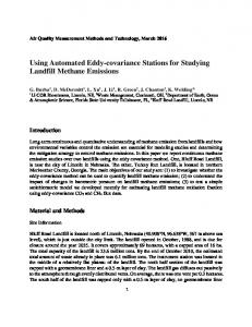
Figure 1. Simplified diagram showing top view of the scale mechanism. The three arms of the mechanism are arranged around a common central point, with the two diagonal arms being able to pivot in the vertical direction. The outer circle shows the positions of support posts, which the arms rest on. The inner circle shows the positions where the scale platform rests on top of the arms. The end of the central arm rests on the load cell. As the load is applied to the scale platform, the arms transmit the force to the load cell which flexes. The equidistant arrangement ensures that each arm tilts the same amount, hence limiting the change of orientation of the SQUID.
as such this has not been a major concern at this site. The scale has also been designed to only move vertically even as the loadcell itself flexes, thus limiting the change in sensor orientation as the liquid nitrogen level changes. The actual deviation is still to be measured accurately. The data is captured on a local computer where it can be transmitted to a central database. This method has the advantage of never coming in contact with the liquid nitrogen itself. This avoids ice build-up problems and conduction of heat into the dewar which would decrease the period between refills.
4. Liquid nitrogen refilling Under atmospheric conditions liquid nitrogen’s temperature is just below its boiling point, furthermore when it evaporates it expands by a factor of 694. These facts lead to a convenient method of transferring liquid nitrogen. A tube is placed at the bottom of the refill dewar along with a small heater and the container is sealed. The other end of the tube is placed in the empty SQUID dewar. If the SQUID dewar is normally sealed, it would have to be temporarily unsealed since the transfer depends on a pressure differential between the dewars. A current is then passed through the heater and some of the nitrogen will boil off and pressurise the container. As the pressure builds the liquid nitrogen is forced through the tube and into the empty dewar. In our prototype system, a 2.2 Ohm resistor is used as our heating element and it is powered by a 11.1 V Li-Po battery. This results in a maximum power of 55 Watts and a transfer rate of 1.8 l/min. In the process of transferring 18.2 litres of liquid nitrogen, approximately 0.45 litres is lost. Thus, the transfer loss is about 2.5%.
5. Coil system 5.1 Zero field cooling According to Clarke and Braginski [1], as the magnetic field in which the SQUIDs are cooled is reduced the low frequency noise of the SQUID is also reduced [1]. It should be noted that according 02003-p.3
E3S Web of Conferences
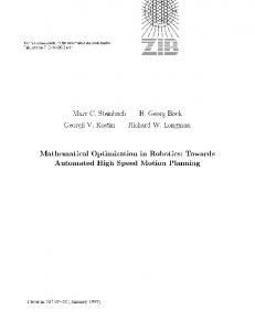
Figure 2. Coils approximately aligned to Magnetic North.
to experimental evidence given by Dantsker et al. [2] the increase of 1/f noise is only significant if the cooling field is greater than approximately 33 uT, depending on SQUID geometry. To reduce vortex formation, that leads to the increased noise, it was decided to shield the SQUID using a three axis Helmholtz coil as opposed to traditional mu-metal shielding. The reason is that mu-metal shielding attenuates the geomagnetic field that we try to measure, while coil-driven field cancellations merely subtract a fixed static field and can be electronically removed. The coils would be placed around the liquid nitrogen dewar and used to cancel the Earth’s static magnetic field at their centre. The SQUID would then be lowered into the dewar and once in place would be forced into normal conducting mode by using the SQUID’s internal heater. This would result in the SQUID cooling in a near zero magnetic field without any motion. Once the SQUID cools, the control system of the SQUID is switched o ff, the current in the coils is then reduced very gradually. Once this has been done, the SQUIDs can be switched on and tuned. The coils and control systems we are currently using to test this procedure are not adequate to perform the tests reliably. The coils were not powerful enough to perform both low and high field cooling tests for comparison and the digital current source driving the coils has a low resolution which results in relatively large (25 nT) jumps as the coils are switched off . However, the tests that have been done have shown a potential decrease in noise levels. A more suitable coils system is currently under development and should provide conclusive results.
5.2 SQUID alignment In order for the data to be consistent with magnetic observatories around the world, the SQUID needs to be aligned to True North. The following procedure attempts to eliminate any small tolerances in the system while still allowing for accurate alignment of the SQUID. A Helmholtz coil system is placed where the SQUID is to be installed and its X-axis is aligned roughly to Magnetic North. A fluxgate magnetometer is placed at the center of the coil system. The fluxgate is rotated until its X-axis is aligned with Magnetic North. When it is aligned the X-channel will be at a maximum, while the Y-channel is at a minimum. This will only be accurate if there is nothing in the area that distorts the orientation of the Earth’s magnetic field. 02003-p.4
i-DUST 2014
Figure 3. Fluxgate magnetometer placed at center of coil system.
Figure 4. Fluxgate magnetometer used to align coils to Magnetic North.
An alternating current is then passed through the X-axis of the coils (with the frequency being well within the bandwidth of the fluxgate). The coils are then rotated until the maximum field is detected on the X-channel of the fluxgate and a minimum on the Y-channel. It is important to ensure that the fluxgate does not move during this step. The coils are now aligned to Magnetic North. The average magnetic declination of the day can then be programmed into the control system of the coils, and hence they will be able to generate a True North magnetic field. Once the SQUID is placed inside the coil system and cooled, a small alternating magnetic field can be generated in the direction of True North. Similar to before, the SQUID can be rotated until the maximum alternating field appears on its X-channel and a minimum on its Y-channel. 5.3 Helmholtz coil calibration The coils will be used to assist with alignment of the SQUID sensors to True North. However, it is very difficult to produce a three axis coil system where the axis are perfectly perpendicular. The control system of the coils can be used to correct for coil misalignments by making use of matrix manipulation. 02003-p.5
E3S Web of Conferences Using a matrix it is possible to describe the correlation between the various axes, B � = AB,
(1)
Bx� �x � x �x � y �x � z Bx � � By = �y x �y � y �y � z By Bx� �z � x �z � y �z � z Bx where A is the correlation matrix with �xy describing the effect on the generated x-field by the y-field command, B is the desired field, and B0 is the actual generated field. It is possible to estimate the correlation matrix by placing a 3-axis reference magnetometer at the centre of the coil system and energising one coil at a time. Thus, by finding the inverse of the correlation matrix, A, and multiplying by the requested field a modified requested field can be found. If this modified field request is sent to the coil control system instead, then the system should be able to compensate for the misalignments. B � = ABmod = A(A−1 B) = B.
(2)
The average error magnitude without correction was found to be 380 nT, while using the correction matrix reduced this error to 3 nT in the same test.
6. Conclusion Thus far we have learned that a three axis Helmholtz coil would be useful to cool the SQUIDs in a low magnetic field and as an alignment aid to True North. It may be possible to run the station off renewable energy sources and generate the cryogen on site, thus limiting maintenance trips. Furthermore, a simple method for transferring liquid nitrogen from a refill dewar has been developed as well a method for monitoring the cryogen level. Other factors briefly discussed include site selection as well as construction materials. It is believed that once these and other issues are properly understood and solved it should be feasible to construct remote SQUID monitoring stations for geomagnetic measurements. References [1] J. Clarke, A.I. Braginski, The SQUID Handbook: Vol.1 Fundamentals and Technology of SQUIDs and SQUID Systems, Whiley-VCH, Pages 200–204 (2004). [2] E. Dantsker, S. Tanaka, et al., Reduction of 1/f noise in high-Tc dc superconducting quantum interference devices cooled in an ambient magnetic field, Applied Physics Letters, Vol. 69, No. 26, Pages 4099–4101 (1996). [3] C.M. Schlinger, Mangetometer and Gradiometer Surveys for Detection of Underground Storage Tanks, Bulletin of the Association of Engineering Geologists (1990). [4] B. St-Louis, et al., Intermagnet Technical Reference Manual: Version 4.6, INTERMAGNET (2012).
02003-p.6