density (PSD) of noise inside a combustion chamber can be determined accurately only if the influence of ..... www.cerfacs.fr/4-26334-The-AVBP-code.php ...
179
Center for Turbulence Research Proceedings of the Summer Program 2014
Towards concurrent identification of flame dynamics and combustion noise of enclosed flames By C. F. Silva†, W. Polifke†, J. O’Brien
AND
M. Ihme
The purpose of this work is to highlight the importance of taking into account the two-way interaction between flame and acoustics in the prediction of combustion noise generated by enclosed turbulent flames. It is argued that in general the power spectral density (PSD) of noise inside a combustion chamber can be determined accurately only if the influence of acoustics on the flame is considered in an adequate manner. Consequently, this work presents two techniques based on system identification (SI) to retrieve from global values of heat release rate, the sources of combustion noise as well as acoustic signals produced by acoustic excitation.
1. Introduction Predicting noise produced by turbulent flames is of interest in the field of combustion acoustics. An established hybrid technique for open flames divides the problem in two parts: firstly, sources of combustion noise are computed from the unsteady Navier-Stokes equations using reliable computational fluid dynamics (CFD) tools. Often, when studying premixed flames, only the unsteady heat release rate q˙0 is considered, because it dominates other sources of noise (Strahle 1971). Secondly, the sound radiated by q˙0 is evaluated by solving a suitable form of the wave equation that accounts for the acoustic scattering of the propagation medium. Weyermann (2010) and Silva et al. (2013) have extended hybrid methods to the case of confined flames. One important difference is that now the reflection of acoustic waves at the boundaries should be accounted for. Using a numerical tool to solve the nonhomogeneous 3D Helmholtz equation, Silva et al. (2013) compared results of hybrid and direct methods, where the latter is a computationally expensive approach that evaluates simultaneously the acoustic sources and the corresponding acoustic field. For some cases, significant mismatch in terms of the estimated PSD was observed. Weyermann (2010) considered low frequencies in the framework of a compact model: an integrated (global) heat release rate Q˙ 0s was taken into account instead of its local distribution, and acoustic network models were used to compute the acoustic waves produced by Q˙ 0s . Standard hybrid methods are based on one-way coupling: while the combustion noise sources produce acoustic waves, the waves generated do not act back on the source. Such an approach is correct if the flame is unconfined. However, if the flame is enclosed in a combustion chamber, a two-way interaction between the acoustics and the turbulent flame should be expected. There are, accordingly, not two but three important factors when evaluating noise levels in a combustion chamber: the source of combustion noise Q˙ 0s , the corresponding acoustic waves radiated and reflected/scattered throughout the domain and boundaries, and the effect of acoustic flow perturbations on the flame. The latter effect results in fluctuations of heat release Q˙ 0c and may be described by a flame † Fachgebiet f¨ ur Thermodynamik, Technische Universit¨ at M¨ unchen, Germany
180
Silva et al.
et
+
nc X
1+
ck q
et
vt
k
+
k
dk q
k=1
st
+
,
nb X
1+
nc X
k=1
fk q
k
ck q
k
vt
ck q
nb X
bk q
k
y˜t
k
k=1
bk q
y˜t
k
+
yt
st
+
,
nb X
+
yt
k=0
k=0 nf X
nc X
k=1
k=1 nd X
1+
bk q
k
k=0
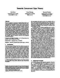
Figure 1. Box-Jenkins model for a SISO system. Complete (left). Simplified (right).
transfer function (FTF), or a corresponding acoustic scattering matrix (Paschereit et al. 2002). If the fluctuations of heat release rate produced by the flame Q˙ 0s and the FTF are available, it is possible to compute a global heat release rate Q˙ 0 as the sum of both contributions Q˙ 0s + Q˙ 0c . The work of Weyermann (2010) shows that the inclusion of Q˙ 0c is crucial and accounts for several otherwise inexplicable features of the experimentally obtained PSD. The present work argues that evaluating both Q˙ 0s and Q˙ 0c is a key point for the proper estimation of combustion noise in confined combustion systems. Furthermore, a methodology based on system identification polynomial models is introduced, which allows to estimate the contributions Q˙ 0s and Q˙ 0c from (experimental or numerical) time series data of the overall heat release Q˙ 0 . This article is organized as follows. In the next section a brief overview of system identification is given (Ljung 1999; Polifke 2014). Then the approach used in this work to estimate noise in single input single output (SISO) systems is explained in some detail. The fourth section introduces the configuration under study: a laminar premixed Bunsen type flame. The identification of the frequency response of this flame to perturbations of upstream velocity, as well as equivalence ratio, is performed with and without external noise. In section five, PSDs observed in DNS of a laminar premix flame with an imposed random source term are compared against corresponding results from network models with one- and two-way coupling, respectively. It is found that two-way coupling can generate strong resonance peaks in the PSD, which the hybrid model with one-way coupling fails to capture.
2. Overview of system identification 2.1. SISO model System identification (SI) (Ljung 1999) combines the fields of estimation theory, theory of random processes, signal processing and systems theory. When a system is considered as linear time invariant (LTI), it is possible to use linear SI theory to infer polynomial models simply by accounting for input s and output y signals. In this situation, the system is viewed as a black box, as illustrated in Figure 1. The output signal y at time t is considered to be the sum of two contributions yt = y˜t + vt .
(2.1)
The first contribution, noted as y˜t , is the noise-free output caused by present and past inputs st−k interacting with the system summed to the influence of past noise-free outputs, as depicted in Figure 1(left). The corresponding polynomial representation for a
181
Identification of combustion noise single input single output (SISO) system reads y˜t = f1 y˜t−1 + f2 y˜t−2 + · · · + fnf y˜t−nf + b0 st + b1 st−1 + · · · + bnb st−nb ,
(2.2)
where fk and bk are constant coefficients at a sample time t − k. The second contribution comes from the noise that contaminates y˜t . On the basis of the polynomial model, this noise, which is modeled as a filtered white noise time series e, is expressed as a linear combination of present and past e summed to a linear combination of past v vt = d1 vt−1 + d2 vt−2 + · · · + dnd vt−nd + et + c1 et−1 + · · · + cnc et−nc ,
(2.3)
where ck and dk are constants at a sample time t − k. Let us now introduce the shift operator q −k st = st−k , so that we can define four polynomials B(q), C(q), D(q), and F (q) so that B(q) =
nb X
bk q
−k
, C(q) = 1+
k=0
nc X
ck q
−k
, D(q) = 1+
k=1
nd X
dk q
−k
, and F (q) = 1+
nf X
fk q −k .
k=1
k=1
The output signal yt can be now compactly written as
C(q) B(q) st + et F (q) D(q)
(2.4)
yt = G(q) st + H(q) et .
(2.5)
yt = and generalized to
Equation (2.4) is recognized as the Box-Jenkins (BJ) model of the system depicted in Figure 1. This polynomial model describes both deterministic y˜t (plant) and stochastic part vt of the system as being autoregressive, i.e. subsystems in which internal feedback may be present. In this situation both impulse responses G(q) and H(q), of plant and noise, respectively, decay asymptotically and sometimes very slowly. If autoregressive characteristics of these subsystems are not to be expected, it is possible to make D(q) = F (q) = 1, as illustrated in Figure 1 (right). It will be observed later in this article, that the impulse response of flames to both velocity and equivalence ratio perturbations are compact and, consequently, not considered autoregressive, so that G(q) = B(q). This is not always the case for H(q). However, if no sharp cut-off frequencies in the spectrum of noise are expected, one may assume that H(q) = C(q). This leads to a simplified BJ model, yt = B(q) ut + C(q) et ,
(2.6)
which is the one used in the present study. The model of noise v(t) = C(q) et is known as Moving Average (MA). Further on, if C(q) = 1 then Eq. (2.6) reduces to a Finite Impulse Response (FIR) model. Once the models have been chosen (Box Jenkins, simplified Box Jenkins, MA, FIR) the next step is to find a suitable number and value of coefficients for the polynomials B(q), C(q), D(q), and F (q). Techniques based on Maximum Likelihood Estimation (MLE) approaches are used to find these coefficients for BJ and MA models. For FIR models, approaches based on minimum least squares are preferred (Ljung 1999). 2.2. MISO model and frequency response (1)
Let us express a multiple input single output (MISO) model for two inputs (st (2) st ) and in the absence of noise (vt = 0) as (1)
(2)
yt = B (1) (q) st + B (2) (q) st ,
and (2.7)
182
Silva et al.
in which compact impulse responses B (1) (q) and B (2) (q) are considered and therefore F (1) = F (2) = 1. Equation (2.7) describes a FIR model for a MISO system. In addition to the system impulse response, which is defined in time, it is also useful to analyze the frequency response of systems. For LTI systems, the frequency response F(ω) is obtained by means of the Fourier transform as follows F(ω) =
L X
gk e−iωk∆t ,
(2.8)
k=0
where gk is the coefficient k of the impulse response defined by the polynomial G(q), L is the length of the truncated impulse response, ω is the angular frequency, and ∆t is the sample time of the time series under consideration.
3. System identification, flame dynamics and combustion noise 3.1. Turbulent premixed flames Consider the unsteady heat release rate as principal source of acoustic production: ˆ˙ (ω), ˆ˙ (ω) + Q ˆ˙ Q(ω) =Q s c
(3.1)
¯˙ and fluctuating quantity Q˙ 0 where the quantity Q˙ has been decomposed in its mean Q ˆ˙ iωt . Equation (3.1) shows and harmonic oscillations have been considered so that Q˙ 0 = Qe two contributions. The first one is written as ¯ ˆ˙ (ω) = Q˙ c u ˆFu (ω), (3.2) Q c u ¯ where Fu (ω) is the frequency response of the flame to velocity perturbations u ˆ at a ˆ ˙ reference point upstream from the flame. The second contribution Qs is recognized as the source of combustion noise. In the time domain, Eq. (3.1) can be written in the form of Eq. (2.6): nb X yt = bk st−k + vt , (3.3) k=0
Pnc ¯˙ u0 /¯ ˙0 for yt = Q˙ 0t , st = Q c t u and vt = et + k=1 ck et−k = Qs,t . The simplified BJ model structure represented in Eq. (3.3) and illustrated in Figure 1(right) allows us to decompose the global heat release rate Q˙ 0t , which is the measured output, as the convolution of the flame impulse response bk with velocity perturbations summed to combustion noise, here considered as color noise, i.e. white noise et convoluted with a filter ck . The whole problem summarizes then in finding suitable values for every coefficient bk , ck , and noise variance var(et ). This corresponds to estimate flame dynamics and combustion noise from time series of input u0 and output Q˙ 0t . 3.2. Laminar premixed flames In the present section the approach to identify noise together with the dynamics of a confined laminar flame is explained. Note that a steady laminar flame does not produce any noise. Furthermore, if this flame is acoustically excited by velocity perturbations u0 , any acoustic wave measured in the system is a result of this external acoustic excitation. The global heat release rate in this case is simply Q˙ = Q˙ c because v = 0. Let us now add a second input to the system with the objective of producing additional contributions
Identification of combustion noise
183
to the fluctuating heat release that is not related to the acoustic excitation u0 . In this study, this additional input is chosen to be the equivalence ratio φ. If the flame response to velocity and equivalence ratio perturbations is evaluated separately, we consider two SISO systems described by FIR models, as follows: nb ¯˙ (u) X Q c (u) (u) bk ut Q˙ t = u ¯ k=0
nb ¯˙ (φ) X Q c (φ) (φ) and Q˙ t = ¯ b φt , φ k=0 k
(3.4)
where the apostrophe ()0 has been dropped to improve readability. The previous two cases can be put together in on MISO structure nb nb ¯˙ (φ) X ¯˙ (u) X Q Q c c (u) (φ) ˙ bk ut + ¯ bk φt , Qt = u ¯ φ k=0 k=0
(3.5)
if Q˙ (u) and Q˙ (φ) are uncorrelated. This condition is respected if φ fluctuations are produced only by fluctuations of fuel and not of the oxidizer. In order to obtain the impulse (u) (φ) responses bk and bk we need to know three signals: two corresponding to the inputs ut and φt , and one corresponding to the output Q˙ t . Let us pretend that we have no knowledge of φ, such that Q˙ 0c must be considered as noise in the identification process. In that case, Eq. (3.5) can be approximated to nb ¯˙ (u) X Q c (u) Q˙ t ≈ bk ut + vt , u ¯
(3.6)
k=0
where vt is the noise corresponding to the heat release rate produced by the ‘unknown’ contribution of the second term of Eq. (3.5). It is interesting to notice that, by doing so, we are studying the same model structure as in Section 3.1 (Eq. (3.3)). (u)
3.2.1. Assessing bk
and ck by FIR+MA
The first technique is to consider Eq. (3.6) as a FIR model. Considering that v is weakly (u) correlated with Q˙ c implies assuming that v is low correlated with u. Accordingly, solving the corresponding over constrained linear system (Eq. (3.6)) for different values of t by minimum least squares leads to diminishing the influence of noise v on the estimation (u) of bk . Note that this is the classical assumption when modeling a system through a FIR structure. Ideally, if the noise is truly white noise (v ≈ e) there will be no influence of noise on the results. Be aware, however, that in the present case v is colored noise. (u) Once the impulse response bk is estimated, it is possible to evaluate v by rearranging Eq. (3.6): nb ¯˙ (u) X Q c (u) vt ≈ Q˙ t − bk ut . (3.7) u ¯ k=0
The next step is to apply a MA model for vt as vt = e t +
nc X
ck et−k ,
(3.8)
k=1 (u)
so that the coefficients ck are obtained. Note that if bk consequently ck will also be poorly estimated.
is poorly estimated, vt and
184
Silva et al. 2 mm
Rout l4 l3
Tw
f
=)
Td
mic2
=)
3 mm
g
Compact Flame
)
mic1
)
l2 l1
Ta
Rin
uin
Figure 2. Test rig configuration (Kornilov et al. 2009) (left). Corresponding network model (right). (u)
3.2.2. Assessing bk
and ck by BJ
We can directly consider Eq. (3.6) as a Box-Jenkins like structure: nb nc ¯˙ (u) X X Q c (u) ck et−k . bk ut + et + Q˙ t ≈ u ¯ k=0
(3.9)
k=1
(u)
By applying MLE methods, it is possible to obtain simultaneously bk ck , i.e. to estimate simultaneously flame dynamics and noise from data containing time series of Q˙ and u.
4. Identification of flame response and noise with SISO and MISO models The laminar premixed Bunsen-type flame under study is stabilized at a flat perforated plate, as shown in Figure 2. A premixed mixture of methane and air, with equivalence ratio φ = 0.8, is introduced at the bottom of the configuration with a velocity of 0.4 m.s−1 . This configuration was built and studied in the work of Kornilov et al. (2009). The operating and thermal conditions, illustrated in Figure 2, are φ¯ = 0.8, uin = 0.4 m.s−1 , Td = 293 K, Ta = 293 K, and Tw = 373 K. The solver AVBP† is the numerical tool used in this study to solve the full compressible Navier-Stokes equations via direct numerical simulation (DNS). Boundary conditions are based on the Navier-Stokes characteristic boundary conditions (NSCBC) method. In this study, a two-step chemistry (2S-CM2) for methane is used (Duchaine et al. 2011; Silva et al. 2014). The flame front is resolved by 8 grid points. (u) (φ) In order to identify the impulse responses bk and bk of the flame as two SISO structures, see Eq. (3.4), it is necessary to perform two different DNS, one for velocity perturbations and other for equivalence ratio perturbations. Subsequently, two independent series of data are retrieved corresponding to (u, Q˙ (u) ) and (φ, Q˙ (φ) ). System identification is performed on this data. Results for the corresponding frequency responses are shown in Figure 3. There is no necessity to carry out two independent DNS to retrieve the linear flame response to two independent inputs. In fact, as long as u and φ are uncorrelated, the † www.cerfacs.fr/4-26334-The-AVBP-code.php
185
Identification of combustion noise 1.6 Exp. SISO MISO
1.4
SISO MISO
2.5
1.2
2
1.5
Gain Gain
Gain Gain
1 0.8 0.6
1
0.4
0.5 0.2 0 0
200
400 600 Frequency (Hz)
800
0 0
1000
200
400 600 Frequency (Hz)
800
1000
Frequency (Hz)
Frequency (Hz)
Figure 3. Two SISO models Vs One MISO model. Fu (ω) (left). Fφ (ω) (right). MISO (black line). SISO (gray line). Experiments (Kornilov et al. 2009) (dashed line). −4
2.5
Truth FIR Box−Jenkins
SNR = 2 SNR = 4
2
5
4
SNR = 2 3
PSD
2
2
SNR = 4
1
0.5
200
300 400 Frequency (Hz)
Truth Box−Jenkins 4
SNR = 2
1
100
x 10
Truth FIR
PSD PSD SPL
Gain Gain
−4
x 10
3
1.5
0 0
5
500
Frequency (Hz)
600
700
0 0
SNR = 4
1
200
400
600
800
Frequency (Hz) Frequency (Hz)
0 10000
200
400
600
800
Frequency (Hz) Frequency (Hz)
1000
Figure 4. Modeling frequency response and noise. Fu (ω) Truth vs FIR-MA vs BJ (left). Noise spectrum v, Truth vs FIR-MA (center). Noise spectrum v, Truth vs BJ (right). True values, shown in black lines, are obtained from MISO model.
global heat release rate is simply the sum of the two contributions Q˙ = Q˙ (u) + Q˙ (φ) . A MISO structure (see Eq. (3.5)) is therefore suited for such a case. Results, which are ˙ are shown in Figure 3. The idea obtained after applying SI to data containing (u, φ, Q), (φ) ˙ now is to consider the contribution Q as noise, because φ is assumed to be unknown. ˙ Is The model of the system is now given by Eq. (3.6) and the data available is only (u, Q). (φ) ˙ it possible to estimate Qt even in the absence of knowledge of φt ? The latter is assumed to be possible if a good estimation of vt is performed. Results are shown in Figure 4 for two different levels of signal-to-noise ratio and for the two approaches considered, i.e. FIR+MA and BJ (see section 3.2). The influence of (u)
SNR =
var(Q˙ c ) , var(v)
(4.1)
on results is as expected: the higher the fluctuation amplitudes of v with respect to the perturbation amplitudes of Q˙ (u) , the more difficult it is to estimate correctly the frequency response Fu (ω). It is also observed that the BJ method gives slightly better results than FIR+MA, specially in the frequency band between 100-200 Hz for both values of SNR.
5. Assessing acoustic levels of a confined laminar premixed flame The purpose of this section is to compute the levels of noise produced by a confined, laminar premixed flame subjected to broadband forcing of equivalence ratio. This setup
186
Silva et al.
emulates an enclosed turbulent premixed flame without any type of external excitation. Three different setups of the system enclosing the laminar flame are studied, which are related to high (case A), medium (case B) and low (case C) acoustic reflection at both inlet and outlet (see Figure 5). First, the direct method is considered to compute noise in the confined domain. Accordingly, DNS of the three configurations is carried out and acoustic waves f and g are recorded at two locations ‘mic1’ and ‘mic2’, see Figure 2. Secondly, a hybrid method is formulated. The source of noise vt , computed in Section 4, (u) is introduced in a network model together with Q˙ c . The latter is given as a function of Fu (ω) (see Eq. (3.2)) in order to account for the coupling between acoustics and the flame. Note that no perturbations of velocity are introduced from external forcing. Any perturbation of velocity will be related only to the acoustic waves generated by the source v. 5.1. Acoustic network model Let us define two elements, one describing a duct and other describing a cross-section jump in which a plane flame is attached. The two corresponding transfer matrices read: � � � −iω l /c � 1 ξ + α + αθF(ω) ξ − α − αθFu (ω) e um u 0 , Tu,m = and T = F 0 eiωu lm /cu 2 ξ − α − αθF(ω) ξ + α + αθFu (ω) (5.1) where ξ = ρu cu /ρd cd , and α = Au /Ad , θ = (Td /Tu − 1) denotes the specific acoustic impedance, the area change, and the relative temperature increment. The matrices describing the inlet and outlet acoustic boundary conditions, the vector of waves, and the source vector are given by � � � � � � � � (γ − 1) 1 −rin (ω) 0 0 fp 1 Rin = , Rout = , Wp = , S= vˆω , (5.2) 0 0 −rout (ω) 1 gp −1 γ p¯Au where vˆω is the discrete Fourier transform of vt and the acoustic waves f and g are defined as � � � � 1 pˆ 1 pˆ +u ˆ and g= −u ˆ . (5.3) f= 2 ρ¯c¯ 2 ρ¯c¯ The quantities p, u, ρ, and c stand for the pressure, velocity, density, and sound speed, respectively. Considering the previous defined matrices and defining I as a 2×2 identity matrix, the acoustic network model for the system depicted in Figure 2 (right) reads: Rin Rout Win Tu,1 Wmic1 I Wu Tu,2 I (5.4) Wd = S . TF I Wmic2 Td,3 I Td,4 I Wout The linear system, defined in Eq. (5.4), must be solved for each frequency of interest. In this work, it was solved 1000 times for frequencies ranging from 1 Hz to 1000 Hz. 5.2. Results One of the objectives of this work is to emphasize the importance of including Fu (ω) when evaluating combustion noise by network models, and eventually by 3D acoustic solvers. With this in mind, we first estimate the noise produced by the flame while neglecting acoustic-flame interactions Fu (ω) = 0. Figure 6 shows the PSD of acoustic waves f and
187
Identification of combustion noise 1.5
4 Case A Case B Case C
|R| |R| 0.5
Rout
1 0
C
0 0
200 400 Frequency (Hz) Frequency (Hz)
600
A B C
Rin
−1
B
B C
2
Phase arg(R)
A
1
A
3
−2 −3 0
200 400 Frequency (Hw) Frequency (Hz)
600
Figure 5. Reflection coefficients for the three cases under study. Modulus (left). Argument (right). Case A (black line). Case B (gray line). Case C (dashed line).
g
g
f
f
f
PSD
g f
g
f
g
g
f Case A
Case B
Case C
Case A
Case B
Case C
Figure 6. PSD of acoustic waves for the three cases under study. Left: mic1, Right: mic2. DNS (black line). Network model with Fu (ω) 6= 0 (gray line). Network model with Fu (ω) = 0 (dashed line).
g for cases A, B and C. Whereas estimation of noise in cases A and B is satisfactory, the same cannot be stated for case C, since the peak at 160 Hz obtained by DNS is not well captured. If flame-acoustic coupling is introduced in the network model by accounting for the Fu (ω) of the flame, much better results are obtained. The downstream f and upstream g acoustic waves are predicted satisfactorily for all cases. The attention now is turned to the value of the main peak encountered in case C. It is remarkable that strong peaks are observed for a case with very low acoustic reflection, because this is a particular situation for which a great amount of acoustic energy is dissipated. Furthermore, cavity resonance frequencies of the case under study are above 20000 Hz. In order to understand the origin of these peaks, we refer to -(Bomberg et al. 2014; Courtine et al. 2014; Silva et al. 2014), where the concept of Intrinsic ThermoAcoustic (ITA) feedback is introduced and discussed. In the present case, the first ITA mode is predicted at 147 Hz, suggesting that the acoustic peak present in the PSD diagram is indeed a result of ITA coupling.
6. Conclusions The proper formulation of hybrid approaches to evaluate levels of noise in confined domains was the subject of this study. The importance of considering a two-way inter-
188
Silva et al.
action between flame and acoustics was highlighted. It was observed that ITA resonance may occur in a combustion chamber with low acoustic reflection at boundaries. If the influence of the acoustic field on the flame is ignored, the resonance peak produced by the ITA coupling is not recovered. In contrast, satisfactory results are obtained once this influence is modeled by the flame frequency response Fu (ω). Note that in a configuration where acoustic frequencies related to cavity resonances are lower - as they would be in practical combustor configurations - acoustic coupling would lead to additional resonance phenomena, which also require inclusion of flame dynamics in combustion noise analysis. The study demonstrates that both combustion noise source terms v and frequency response Fu (ω) are important and that both must be included when computing noise in confined domains. A second related difficult is also addressed in this work. A technique was developed to extract simultaneously both v and Fu (ω) from time series composed only by velocity fluctuations upstream of the flame and by a global measurement of overall heat release rate Q˙ 0 . Both v and Fu (ω) were well estimated as long as SNR was larger than four. The technique of BJ was proved to be slightly better than the one named FIR-MA. REFERENCES
Bomberg, Sebastian, Emmert, Thomas & Polifke, Wolfgang 2014 Thermal versus acoustic response of velocity sensitive premixed flames. Proc. Combust. Inst., In Press. Courtine, E., Selle, L., Nicoud, F., Polifke, W., Silva, C. F., Bauerheim, M. & Poinsot, T. 2014 Causality and intrinsic thermoacoustic instability modes. Proceedings of the Summer Program, Center for Turbulence Research, Stanford University, pp. 169–178. Duchaine, F., Boudy, F., Durox, D. & Poinsot, T. 2011 Sensitivity analysis of transfer functions of laminar flames. Combust. Flame 158, 2384–2394. Kornilov, V.N., Rook, R., ten Thije Boonkkamp, J.H.M. & de Goey, L.P.H. 2009 Experimental and numerical investigation of the acoustic response of multi-slit Bunsen burners. Combust. Flame 156, 1957–1970. Ljung, L. 1999 System identification - Theory for the user . Prentice Hall. 2nd Edition. Paschereit, C. O., Schuermans, B., Polifke, W. & Mattson, O. 2002 Measurement of transfer matrices and source terms of premixed flames. J. Eng. Gas Turb. Power 124, 239–247. Polifke, W. 2014 Black-box system identification for reduced order model construction. Annu. Nucl. Energy 67, 109–128. Silva, C. F., Emmert, T., Jaensch, S. & Polifke, W. 2014 Numerical study on intrinsic thermoacoustic instability of a laminar premixed flame. Submitted to Combust. Flame. Silva, C. F., Leyko, M., Nicoud, F. & Moreau, S. 2013 Assessment of combustion noise in a premixed swirled combustor via large-eddy simulation. Comput. Fluids 78, 1 – 9. Strahle, W. C. 1971 On combustion generated noise. J. Fluid Mech. 49, 399–414. Weyermann, F. 2010 Numerische Berechnung der Emission verbrennungsinduzierten L¨ arms automobiler Zusatzheizungen. PhD thesis, Technische Universit¨at M¨ unchen.