ance Infrastructure (infrastructure-controlled FT) or directly by the application ... designer of the application is fully responsible for the replica maintenance in-.
Towards Dependability Modeling of FT-CORBA Architectures Istv´an Majzik? and G´abor Huszerl Department of Measurement and Information Systems Budapest University of Technology and Economics Magyar Tud´ osok krt. 2., H-1117 Budapest, Hungary {majzik, huszerl}@mit.bme.hu http://www.mit.bme.hu/
Abstract. The paper presents techniques to support the dependability modeling and analysis of distributed object-oriented applications that are designed according to the Fault Tolerant CORBA (FT-CORBA) specification. First the construction of a high-level dependability model is described. It is based on the architecture of the application and allows the analysis of the fault tolerance strategies and properties that are directly supported by the standard infrastructure. Then a technique to construct a refined dependability model is presented. It exploits the detailed behavioral model of the object responsible for replica maintenance. The UML statechart of this object is transformed to a stochastic Petri net that forms the core of the dependability model. In this way the designer is allowed to utilize the full power of statecharts to construct models of application-dependent replication strategies and recovery policies.
1
Introduction
The need for distributed object-oriented systems has led to the development of middlewares that allow the interaction of objects regardless of their specific platforms and implementation languages. The Common Object Request Broker Architecture (CORBA) is such a middleware standardized by the Object Management Group (OMG). CORBA defines the basic mechanisms for remote object invocation through the Object Request Broker (ORB). Fault Tolerant CORBA (FT-CORBA) is a general framework for CORBAbased systems that need fault tolerance (FT) [1]. Applications ranging from small, embedded systems to wide area communication networks can utilize the infrastructure defined in the standard and implemented by commercial CORBA providers [2]. In FT-CORBA, single point of failures caused by single objects are avoided by replicating the server objects on a group of hosts. Clients can invoke the ?
This work has been partially supported by the Hungarian Ministry of Education under contract FKFP 0103/2001.
methods of these replicated objects transparently. The creation and maintenance of replicated objects is provided either by the predefined Fault Tolerance Infrastructure (infrastructure-controlled FT) or directly by the application (application-controlled FT). In the case of infrastructure-controlled FT, the availability of a group of replicated objects is determined by a set of properties assigned to the infrastructure. Among others, the initial number of replicas, the minimum number of replicas, the fault monitoring interval and granularity are properties that have to be set carefully to keep the costs at low level and at the same time provide the availability required by the application. In the case of application-controlled FT, the designer of the application is fully responsible for the replica maintenance including activation, recovery and reconfiguration. Application-specific strategies can be elaborated to satisfy requirements that cannot be met by the common implementation of the infrastructure. The complexity of the standard and the lack of mechanized dependability analysis are, among others, obstacles to the widespread use of FT-CORBA. The designer needs support to select the property values of the infrastructure or to construct optimal application-controlled FT strategies. The comparison of solutions, the estimation of the effects of selected property values and the identification of dependability bottlenecks can be supported in the design phase by the construction and analysis of dependability models. Stochastic dependability models using Markov chains or Petri nets (PN) can provide numerical availability figures as well as the sensitivity of system-level measures to the component property values. The paper presents techniques that support the dependability modeling and analysis of FT-CORBA applications. First the creation of an architectural dependability model in the form of a stochastic Petri net is described. It allows the early analysis of infrastructure-controlled FT strategies. This approach is a relatively straightforward adaptation of the methods proposed in previous works [3]. Then a technique to construct a refined dependability model is presented that utilizes the detailed behavioral models of the objects responsible for replica maintenance. The UML statechart models of the replication managers are transformed to a stochastic Petri net that forms the core of the dependability model. In this way a designer is allowed to utilize the full power of statecharts (including event processing and state hierarchy) to construct models of application-dependent replication strategies, repair and recovery policies. In this way the same model is used both for model-based dependability analysis and for (automatic) code generation. The paper is structured as follows. Section 2 presents the basics of the FTCORBA specification, Section 3 gives an overview of interesting trends in dependability modeling. Our approach is outlined in Section 4. The analysis of the effects of the standard properties of the FT infrastructure and the construction of the architectural dependability model are detailed in Section 5. The refinement of this high-level dependability model is introduced in Section 6. The approach is illustrated by examples in Section 7.
2
FT-CORBA
In FT-CORBA, fault tolerance is provided by entity redundancy (i.e. replication of server objects on different hosts of a distributed system), fault detection and error recovery. The fault model assumes object crash failures: in the case of an error the server object will not provide any response to the clients and will not return to normal operation until an explicit recovery. There is no protection against commission faults and correlated faults. The client objects should not be aware of the fact that the server objects are replicated (replication transparency) and should not be aware of a failure or recovery of a server replica (failure transparency). The transparent connection between the client and the server replicas is the responsibility of the ORB of the client. In FT-CORBA both time redundancy (retry) and spatial redundancy (invoking alternative servers) are allowed. The Interoperable Object Group Reference (IOGR) used by the client ORB may contain either the profiles of the server replicas or the profiles of gateways (that can be used e.g. to implement ordered and reliable multicast in the case of active redundancy).
notification Replication Manager
Fault Notifier
Fault Detector
fault reports
is alive
create object
Host 1
Host 2
Host 3
Server Replica 1
Server Replica 2
Client Object Fault Detector
Factory
ORB
ORB
Logging Mechanism
Fault Detector
Factory
ORB
Recovery Mechanism
Logging Mechanism
Recovery Mechanism
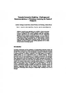
Fig. 1. The architecture of the FT-CORBA redundancy structure
The redundant server objects belong to object groups, and several object groups can be managed together in a fault tolerance domain (FTD). The fault
tolerance infrastructure (FTI) of a domain consists of several objects as follows (Figure 1). The creation and maintenance of the object replicas is provided by the replication manager (RM). The replica objects are continuously monitored by local fault detectors that are deployed on each host. If an object fails then the local fault detector reports the error to the fault notifier. The fault notifier filters and analyzes the incoming error reports and sends a notification to the RM and to other registered objects. The local fault detectors are monitored by a global fault detector that detects when a local fault detector is not available (e.g. if the host fails). In order to increase availability, the objects of the FTI can be replicated as well. In the case of the infrastructure-controlled style, it is the responsibility of the RM to maintain the necessary number of replicas. When it receives a notification about the crash of a replica, then it can initiate the recovery of that replica (by utilizing the logging and recovery mechanisms implemented in the object group) or it can remove the replica from the object group and create a new one (by invoking a factory object that is deployed on the selected host). In the case of application-controlled style, the application is responsible for the maintenance of the replicas, by using the services offered by the fault detectors and notifiers, factory objects and partially by the RM. The reliability and availability of an object group (from the point of view of a client) is determined by a set of properties associated with the group. These properties are summarized in Table 1. They can be set when the object group is created and they can be modified later at run-time. Default values can be assigned to the FT domain or to the type of the server objects. It has to be emphasized that FT-CORBA standardizes the interfaces and responsibility of the FTI, but does not fix the internal implementation of the mechanisms like logging, recovery and group communication.
3
Background
The literature of dependability evaluation presents several useful ideas that have to be followed in our work. It is commonly accepted that the results of dependability analysis are especially important in the early design phase when decisions among architectural alternatives have to be made and dependability bottlenecks have to be found. In this phase dependability evaluation based on analytical modeling deserves particular attention [4, 5]. The dependability model constructed in the early design phase needs to be refined hierarchically as new design information and decisions will be available [6]. In general-purpose architectures the separation of architectural and service concerns is a valuable idea. The architectural failure modes can be mapped separately to service degradation levels interesting to the end-users of the architecture [7]. To allow automated dependability model generation instead of manual modeling, the construction of the dependability model should be based on engineering
Table 1. Fault tolerance properties Property name ReplicationStyle
Values and role STATELESS, WARM PASSIVE, COLD PASSIVE or ACTIVE replication. MembershipStyle Application controlled (MEMB APP CTRL) or infrastructure controlled (MEMB INF CTRL) addition or removal of replicas. ConsistencyStyle Application controlled (CONS APP CTRL) or infrastructure controlled (CONS INF CTRL) logging and recovery of replicas. FaultMonitoringStyle PUSH (“I am alive”) or PULL (“ping”) style monitoring of the replicas. FaultMonitoringGranularity MEMB (each replica), LOC (each location) or LOC AND TYPE (each replica type per location) is monitored. FaultMonitoringInterval Interval of time between successive monitoring requests and the corresponding timeout. Factories The list of objects that create or delete replicas. InitialNumberReplicas Number of replicas when the group is created. MinimumNumberReplicas The number of replicas that must exist to provide the service. CheckpointInterval Time period between successive checkpoints.
modeling languages and automatic model transformations [8]. Results described in [3, 9] show that it is possible to augment CASE environments based on UML with automatic tools that generate dependability models in the form of Petri nets. The method of analyzing redundancy management in distributed objectoriented systems is introduced in our workshop paper [10].
4 4.1
The Modeling Approach Guidelines
First we construct an architecture-based dependability model that takes into account the components and properties of the FTI without requiring the detailed behavioral models of its objects and mechanisms. The standardized structure and properties of the FTI allow us to construct the model and quantify the effects of the alternative values and deployment choices. Then we will support the refinement of the architectural dependability model by focusing on the behavior of the objects of the FTI, especially the (applicationspecific) replication manager. We elaborate how a refined model of the RM can be constructed and integrated with the architectural model. Since the RM contributes directly to maintenance and fault management, i.e. it receives the error messages and decides on the recovery and/or creation
of new replicas, its behavior determines how the failures of replicas may lead to a system failure. Accordingly, it influences the structure of the system-level dependability model. (The analysis of the refined behavior of the components that implement the application functions can contribute to the assignment of more precise dependability attributes like failure rate and latency time.) In general, the careful and purposive selection of the key components to be refined (like the RM in our case) helps to avoid model complexity problems while still keeping the faithfulness of the dependability model at a high level. The dependability of an object group is modeled and analyzed from the point of view of a client application. In this view the mapping from the failures of server replicas (i.e. the architectural failure modes of the object group) to the client (i.e. the service level) is performed by the FT-CORBA compliant ORB of the client. This way the dependability model consists of 3 layers: the hardware layer (hosts), the server replica layer (including maintenance by the FTI) and a layer of mapping from replica failures to the service required by the client. The dependability model is constructed on the basis of the UML model of the FT-CORBA application. This decision is straightforward since UML can be considered as the standard description language of object-oriented systems. In the case of the architectural model, we utilize the package, class and object diagrams. During the refinement, we process the statechart diagrams of the selected objects. The formalism of the dependability model is timed Petri nets (TPN), more precisely Stochastic Reward Nets (SRN) [11]. Dependability measures can be specified by using reward functions. We utilize the outstanding modeling power (e.g. guards assigned to transitions) and the sophisticated solution tools available [12, 13]. In certain cases (e.g. in the case of exponential transition firing times) analytic solution is possible, otherwise simulation has to be performed. 4.2
Assumptions
We adopted the following assumptions during the construction of the dependability model: 1. In the basic model, only crash failures of hosts and server replicas are taken into account. (In Section 5.6, we will include extensions to resolve this restriction.) The effects of the failures of the underlying components of the ORB, the internal logging/recovery mechanisms and group communication should be expressed by the replica failure rates. 2. A crash failure of a host results in immediate crash failures of the objects deployed on that host. The recovery of a replica is always successful except for the case of a host failure. 3. In the case of the infrastructure objects of the FTI, it is assumed that there is no software fault. They may crash due to host failures only. Moreover, we simplify the dependability model by not modeling the maintenance of the replicated FTI objects in detail (it is not specified in FT-CORBA, but may follow the same ideas as that of the server replicas). An implicit recovery is assumed if the host they are deployed on is in healthy state.
4. Conditions specific to the retry mechanism of the client (i.e. expiration time of requests and request duration policy) are not covered. Similarly, continuous heartbeating of the server objects by the clients is not modeled (since it is quite rarely implemented due to high communication costs). 5. We assume that the property values of the object groups are not changed at run-time. They have to be assigned to domains (as default) or to server types (object groups). 4.3
UML modeling
The dependability model is constructed mechanically on the basis of the UML model of the FT-CORBA application. To help in identifying the roles and properties of the objects of the FTI, we introduced the following conventions. Each fault tolerance domain is grouped into a separate package stereotyped as ¿FTDÀ. It contains the predefined objects of the FTI (each identified by a stereotype like ¿replication managerÀ, ¿fault notifierÀ and ¿fault detectorÀ) and embedded packages (with stereotype ¿OGÀ) containing the objects of the replica groups. The initial configuration is modeled by an object diagram. Deployment relations can be modeled by a deployment diagram or by links with stereotype ¿deployed onÀ. In FT-CORBA, the standardized properties of a replica group are defined as common types. The values are accessible through the PropertyManager interface of the RM. Instead of relying on a particular implementation, we assign the properties to the packages of the domain and/or group as UML tagged values. The tag name is the same as the property name, and the value is one of the values defined in the FT-CORBA specification (see Table 1). The values assigned to an object group override the ones assigned to the FT domain. Additional parameters that are not specified in the FT-CORBA will be introduced in the sequel when the dependability submodels are described.
5
The Architectural Dependability Model
The clear interfaces and the separation of the tasks of the different components of the FTI allow a straightforward architectural dependability modeling. The modules (submodels) of the dependability model correspond to the objects (including the objects of the FTI) and to the dependability-related processes like fault activation, error propagation, fault management and recovery. The standard properties of FT-CORBA are mapped to the parameters of the submodels. 5.1
Server Replicas, Hosts and Infrastructure Objects
Each replica is represented by a subnet consisting of TPN places corresponding to the possible states of the object from the point of view of the availability and recoverability of its service. These places will also form the interface towards the other subnets of the model. We distinguish five states (places) as Table 2 shows.
Table 2. States of a replica State Initial state
TPN place Role I The replica was not created yet (but its factory is capable to create it). Primary replica HP The replica is primary and its service is available. Backup replica HB The replica is backup and working correctly. Recoverable failure SF The replica is crashed but it is recoverable. Non-recoverable failure C The replica is crashed and it is not recoverable (due to the failure of its host).
Each replica of the initial configuration (as derived from the UML object and deployment diagrams) is represented by a separate subnet. In these subnets either place HP or HB is marked. Additionally, a subnet is created for each host that is capable of running a replica but does not have any replica deployed in the initial configuration. (This information can be derived from the UML model by recognizing the Factory objects corresponding to that replica type on a given host.) In this case place I of the subnet is marked. The deployment of primary and backup replicas depends on the ReplicationStyle property. If its value is ACTIVE, then all replicas are primary ones, state HB is unnecessary. If its value is COLD PASSIVE or WARM PASSIVE, there is a single primary replica and the others are backup. Hosts are represented by subnets consisting of two places: H (healthy state) and C (crashed). According to Assumption 3, the infrastructure objects of the FTI are modeled in a simplified way: each object is represented by a pair of places H (healthy) and C (crashed). The factory objects need not be modeled separately, since we take into account that the creation of objects is not possible in the case of a host failure. 5.2
Fault Activation and Error Propagation
Fault activation subnets are created for each host and each object. Due to Assumption 1, fault activation is modeled by a timed transition with a single parameter characterizing the (hardware or software) failure rate (UML tagged value FR). Deployment relations and links in the object model initiate error propagation. The failure of a host results in an immediate failure of all objects deployed on it (Assumption 2). The corresponding subnet is depicted in Fig. 2(a). Links among objects of different types indicate communication that may result in error propagation. Besides the direction of the propagation, which is the reverse of the direction of the link, here another parameter, the propagation probability (UML tagged value PP) is introduced. It is mapped to the probability of TPN transitions of the subnet as shown in Fig. 2(b).
R
HP, HB, I, SF
O2
C
HP
SF prop pp
N
H
no_prop
C
1−pp (a)
O1
HP
C
(b)
Fig. 2. Modeling error propagation from a host N to a replica R (a) and from object O1 to object O2 (b). Interface places are depicted by dashed lines
In the case of infrastructure objects, failure (repair) of the host results in the failure (healthiness, respectively) of the object (Assumption 3). The repair of a host is an explicit (external) repair, which is not maintained by the FTI. Accordingly, it is characterized by a repair rate (UML tagged value RR), and represented in the model by a timed transition from place C to H. 5.3
Fault Management
Fault management includes fault detection (performed by the fault detectors) and fault notification (performed by the fault notifiers). Fault handling depends on the following conditions: – Failure of a replica is detected only if the replica is monitored by a local fault detector on its host. In FT-CORBA, it is possible that only representative replicas (one per host or one per type and host) are monitored. This condition can be derived from the deployment diagram (in accordance with the property FaultMonitoringGranularity). – Failure of a host is detected only if the local fault detector of the host is monitored by at least one global fault detector. (The host failure report is to be generated by a global fault detector, since in the case of host failures the local fault detectors will also fail.) – The fault report triggers an action of the RM only if at least one fault notifier and at least one RM are available. These conditions can be combined to form a Boolean expression on the existence and healthiness (state H) of the mentioned infrastructure objects. Boolean expressions can be represented in Petri nets in two ways. In simple nets, the subnets corresponding to AND and OR gates can be constructed explicitly as shown in [14]. In higher level nets, transitions can be assigned enabling conditions that can refer to (simple functions over) markings.
5.4
Replica Maintenance
Replica maintenance includes recovery and reconfiguration of replicas. Here we assume a common implementation, since the standard does not specify the mechanisms but implicitly suggests a “common practice” that is behind the interfaces. In the architectural dependability model the tasks of replica maintenance are modeled by subnets consisting of timed PN transitions. All of them are conditional on the fault management, i.e. they are enabled in the TPN only if the conditions described in the previous subsection hold. In the case of passive replication, the subnets and the additional conditions can be defined as follows: – Recovery of a replica. If a software fault occurs, then the replica is recovered and it becomes a backup. It is modeled by a timed transition from SF to HB, its parameter is the recovery rate (UML tagged value RR). – Activation of a new primary replica. This subnet is a timed transition from HB to HP. The need for a new primary replica is represented by a separate place activate primary, which is another input place of this transition. Activation is required if a primary replica fails either due to a host failure (propagation subnet from place HP to C) or due to a propagated software failure from another object or due to a local software failure (subnets from place HP to SF). Each of these three subnets inserts a token in place activate primary. – Creation of a new backup replica. This subnet is a timed transition from I to HB. The need for a new backup replica is represented by a separate place create backup, which is input place of this transition. Creation of a new backup is required if either a backup fails due to a host failure (subnet from HB to C) or a backup will become primary and the previous primary cannot be recovered to be a backup. This latter case results if the primary fails due to a host failure (propagation subnet from state HP to C) or due to a host failure right after a software failure (propagation subnet from SF to C). Each of these subnets inserts a token in place create backup. The time required to perform the fault handling is dominated by the property FaultMonitoringInterval. Additional time required for recovery (replay of logged messages, proportional with CheckpointInterval) and creation of a replica (by a factory) can be estimated by the designer. Cold and warm passive replication can be distinguished by the time required for recovery and activation. – Shutdown of all replicas. This subnet consists of two immediate transitions from place HP to I and from HB to I. These transitions fire only if the number of working replicas falls below MinimumNumberReplicas (in this case all replicas will be shut down). It happens if the number of replicas being in state C becomes higher than the number of hosts capable of running a replica minus MinimumNumberReplicas. This enabling condition can be expressed by a Boolean function on the markings of places C. If the transition from HP to I (HB to I) fires then a token will be inserted in place activate primary
(create backup, respectively). These tokens will trigger the re-creation of the object group as soon as the number of replicas in state C will decrease (due to the repair of hosts). In order to avoid loops in the TPN, the creation of a new backup is enabled only if the shutdown condition does not hold. At this point, the composition of subnets can be summarized. In the case of hosts and infrastructure objects, the composition of the simplified subnets is presented in Fig. 3.
infrastructure object:
host: λ =RR
prop. of repair
repair H2
C2 prop. of failure
H1
C1 λ =FR
host:
failure H1
C1
Fig. 3. Subnets corresponding to a host (H1, C1) and an infrastructure object (H2, C2)
The composition of the subnets corresponding to server replicas depends on the replication style. In the case of passive replication (COLD PASSIVE or WARM PASSIVE ReplicationStyle), the structure of the composition is shown in Table 3. The model in case of active replication (ACTIVE ReplicationStyle) can be derived from this one by taking into account that all replicas are primary ones. The structure of the model is presented in Fig. 4. 5.5
Client Failover
The client failover strategy determines the behavior of the client ORB when it does not receive the requested service. The ORB can retry the call or invoke alternative servers. FT-CORBA specifies that the client ORB must not fail until it has tried to reach the server object replicas through all profiles available in the IOGR. From the point of view of the client, several mechanisms of FT-CORBA are transparent: Transient failures are tolerated by the retry mechanism; the ORBs of the clients and servers provide mechanism to update the IOGR and thus discover newly created or activated replicas. The client failover subnet maps the failures in the object group to the failure of the service for the client. According to the observations above, the condition of the failure of the service can be expressed by a simple Boolean expression: The service fails if there is no available (i.e. healthy) primary server replica. Accordingly, the failover subnet is a PN representation of a fault tree consisting of a single AND gate. As soon as a primary server replica becomes healthy, the
Table 3. Composition of subnets (passive replication) Subnet Recovery Activation
From To Firing conditions SF HB Fault management HB HP Fault management, activate primary Creation I HB Fault management, create backup, no shutdown condition Shutdown HP I Fault management, min. number of replicas Shutdown HB I Fault management, min. number of replicas Propagation HP C Host failure Propagation Propagation Propagation SW failure Propagation Propagation
HB SF I HP HP C
C C C SF SF I
Host failure Host failure Host failure Object failure Host repair
Action (token to)
activate primary create backup activate primary, create backup create backup create backup activate primary activate primary
client service will be correct. This effect is modeled by the dual counterpart of the above fault tree bounded with the original one [14]. The service is represented by a pair of places OGH and OGC, the server replicas are interfaced to the fault tree through places HP and the other states (that are equivalent from the point of view of the failover condition). 5.6
Possible Extensions
The FTI is specified to handle crash failures only. Commission faults (when an object generates incorrect results) are also interesting for the designer. An anticipated extension of FT-CORBA is the ACTIVE WITH VOTING ReplicationStyle that can protect against these faults. To cover commission faults in the dependability model, the following extensions are necessary: An additional failure state CF has to be inserted in the submodels of the replicas. This state is reached from state HP by a timed transition parameterized with a distinguished commission failure rate. This state is not detected by the FTI (until it changes to crash failure), but it leads to a failure of the service. The failover subnet has to be modified accordingly. Error latency can be modeled by distinguishing an error state (in stateful hosts and objects) that may lead to the failure state by a timed transition. Transient faults can be modeled by implicit repair (transition from the error state to the healthy state.) The subnets that cover these extensions are practically the same as the subnets introduced in [3].
SF Prop. host failure
Recovery of replica
Fault manag.
Prop. host failure Prop. host repair
C
I
Shutdown of replica
Prop. host failure
Local sw. failure
Prop. obj. failure Creation of replica
Fault manag. Min. nr. replica
Fault manag.
HP
create_replica
Fig. 4. Composition of subnets for active replication (conditions are drawn by dashed line)
6
Refinement of the Architectural Dependability Model
The subnets of replica maintenance presented in the previous section assume a typical, common behavior of the RM. Dependability modeling can support the evaluation of specialized maintenance when the vendor of the FTI implements a specific strategy in the RM or the designer implements application-controlled maintenance (by setting MEMB APP CTRL and CONS APP CTRL style and by replacing the RM with her own implementation). In both cases, the detailed behavior of the (new) RM has to be made available in the form of a UML statechart diagram. This statechart model is processed in order to replace the initial subnets presented in Section 5.4 with the specific ones. There is no doubt that the behavior of the RM has crucial effects on the availability of the object group, and the RM has the most sophisticated behavior in the FTI. To be able to model its activities, it seems to be mandatory to support the following features of UML statecharts: – State hierarchy. An RM handles several object groups in an FTD. State hierarchy including concurrent substates is a natural way to model the maintenance of independent groups. – Event processing. In the distributed environment of an FT-CORBA application, the failure reports from fault detectors and the messages of the RM towards the factories and replicas manifest themselves as events. The temporal relations of these events determine when a faulty replica is recovered, how
Table 4. Dependability-related events in an FT-CORBA architecture Event ci di ri pi si fi hi
From To RM Factory RM Factory RM Replica RM RM Fault notifier RM Fault notifier RM Fault notifier RM
Handler create object() remove object() set state() set primary member() push structured event() push structured event() push structured event()
Action/meaning Create a replica Remove a replica Initiate recovery Set the primary replica Replica failed Host failed Host repaired
many replicas are maintained, where a new replica is created, what is the condition of object removal etc. The basic events and the standard handler functions of FT-CORBA are listed in Table 4. We have elaborated the model transformation from UML statecharts to Petri nets with timing and stochastic extensions [15]. This transformation will be utilized to generate the specific subnets of replica maintenance. Note that the statechart model of the RM describes only dependability-related behavior, no application-specific functional details are included. Thus, there is no need to filter out irrelevant states or transitions. In the following, we shortly introduce the model transformation and then define how the subnet (generated automatically from the statechart of the RM) can be integrated with the other subnets. 6.1
From UML Statecharts to Stochastic Petri Nets
Our transformation supports UML statecharts including event processing and state hierarchy. The following restrictions apply: Actions generate events only, events do not have parameters, and history states are not allowed. Since the transformation was detailed in [15], we summarize only the properties that are important from the point of view of the current application. The event queue that connects the state machine with its environment can be parameterized to be a FIFO queue or a set (non-deterministic selection of events). Both implementations use the same TPN interface. Each type of event is represented by a separate place. Tokens representing events from the external subnets are inserted in these places. Similarly, the output tokens (events from the RM) are inserted in another set of places. The semantics of timed transitions is again parameterized: The designer is able to choose among three implementations regarding the policy of transition selection and firing. The stochastic parameters of transitions correspond to the tagged values associated with the UML transitions. In this way time delay or duration of actions can be modeled. The behavior of the resulting TPN satisfies the requirements defined in the UML semantics. The priority relations, the step semantics and the evaluation
of guard conditions are all taken into account and represented by specific constructions in the TPN. By using the transformation, the statechart model of the RM can be mapped to a TPN (SRN) representation with event processing and stochastic parameters corresponding to the UML model. 6.2
Composition of the Subnets
The subnet generated from the statechart model of the RM is integrated with the other subnets of the architectural dependability model by utilizing the event processing mechanism. It means that the state changes of the replicas are “translated” to events. However, to simplify the model, the relatively simple fault monitoring (is alive () calls) and the communication between fault detectors and fault notifiers (push structured fault() calls) are not mapped to events. Instead, the logic conditions of event transmission are represented in the model. In the architectural dependability model, the state changes and the maintenance subnets were integrated by using local conditions and two interface places. Instead of these places, now the places corresponding to the events will be used. The propagation subnets (see Table 3 and Fig. 4) remain unchanged. Tokens representing the events will be generated and processed as follows: – Recoverable failure (transition to state SF) of replica i results in an event si if the replica is monitored by a healthy local fault detector, and at least one of the fault notifiers is healthy. – Failure (transition to state C) of host j results in an event fj if at least one of the global fault detectors is healthy, and one of the fault notifiers is healthy. The repair of the host results in event hj on the same conditions. – Recovery of a replica, activation of a new primary replica and creation of a new backup replica are enabled if the corresponding event from the RM is present (event ri , pi and ci , respectively). The interface places activate primary and create backup are replaced by the places corresponding to events pi and ci for each replica. The conditions of fault handling are not modeled here (since they are involved in the generation of the failure reports). The assumption that replicas are created/activated immediately on a randomly selected host is resolved; the location, time and order of occurrence now depends on the RM. – The subnet representing the shutdown of replica i is replaced by a simple immediate transition that is enabled when a corresponding event di is present. Using the above mentioned input events, it is the responsibility of the RM to keep track of the changes in the system and account for MinimumNumberReplicas.
7
Examples
We present two simple examples just to illustrate the kind of analysis that can be performed.
The first example is an active redundant system that consists of 5 hosts (all capable of running a replica) and initially 3 primary replicas. If a replica fails then a new one is created on a randomly selected host that has no active replica. The architectural dependability model of the system was constructed (Fig. 5). Various parameter settings and the corresponding steady state unavailability (i.e. 1-Availability) of the service of the object group are presented in Table 5. The FaultMonitoringGranularity was varied by changing the number of hosts on which the replica is monitored, assuming a static deployment of fault detectors.
1
t1
r1
OGH
t2
OGF
t3
t4
t5
r2
r3
3
t6
r4
r5
create_replica
Fig. 5. Structure of the example network (the five subnets correspond to the replicas)
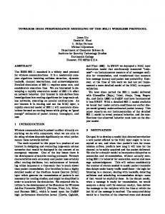
This dependability model was refined by replacing the replica maintenance subnets by a subnet which was generated from the UML statechart model of a non-standard RM implementing a “lazy” recovery strategy. This RM initiates the creation of a new replica as soon as a hardware failure is detected, but delays the recovery from software faults until the failures of at least 2 (or 3) replicas are reported by local fault detectors. In this case the recovery of all failed replicas is performed in parallel. The core of the UML statechart model of the RM is sketched in Fig. 6. Note that the first 5 parallel regions of the statechart keep track of the states of the hosts. The presentation of the sixth region (the maintenance control) is simplified in the Figure by parameterizing the transitions. Here 1 ≤ i, j ≤ 5, i 6= j. The analysis of the dependability model showed that the strategy is effective only if InitialNumberReplicas>3. One of the lessons learnt during these experiments is the following. The statechart-based modeling of the behavior of an RM is cumbersome if we apply the restrictions that events can not have parameters and internal variables are not allowed in the UML model. (Thus, the only way to keep track of the changes
Table 5. Analysis results. Parameter values are set as follows: replica FR=1, RR=100; host FR=0.1 and RR=10, all distributions are exponential. Unavailability is the mean number of tokens in OGF InitialNumberReplicas Unavailability FaultMonitoringInterval Unavailability FaultMonitoringGranularity Unavailability
H2
H1
h1 c1
A1
C1
f1
H3 f2
f1 h2
C2
c2
A2
1 9.89E-3 0.01 1.25E-6 1 1.96E-2
f2
H4 f3
h3 c3
A3
2 1.23E-4 0.02 6.81E-6 2 3.79E-4
C3
f3
c4
A4
4