bandwidths since it takes advantage of scheduled wireless access with 802.16 MCF. We use ... shelf parts such as IEEE 802.11 wireless cards, which use the.
Towards Guaranteed QoS in Mesh Networks: Emulating WiMAX Mesh over WiFi Hardware Petar Djukic and Shahrokh Valaee The Edward S. Rogers Sr. Department of Electrical and Computer Engineering University of Toronto, 10 King’s College Road, Toronto, ON, M5S 3G4, Canada e-mail:{djukic,valaee}@comm.utoronto.ca
Abstract— Currently deployed wireless mesh networks are based on 802.11, WiFi, technology, which is not efficient in multihop scenarios. We present a method for embedding 802.16 packets into 802.11 broadcast packets and padding the 802.11 broadcast payload, so that the broadcasts are aligned to 802.16 TDMA frame boundaries. Our method requires only software changes on the nodes using 802.11a for mesh communications. This means that the mesh networks installed with 802.11a hardware today can be upgraded with a software patch to take advantage of 802.16 MCF and do not have to wait for hardware upgrades to 802.11s. We show that despite the addition of the padding, emulated 802.16 has bandwidths comparable to the bandwidth achievable with 802.16 hardware. The efficiency of the hybrid system is significantly higher than the efficiency of 802.11 based systems. The new system can also provide deterministic guarantees on link bandwidths since it takes advantage of scheduled wireless access with 802.16 MCF. We use ns2 simulations to show the improved efficiency and guaranteed link bandwidth of the 802.11 based hardware using the emulated 802.16 MCF. Index Terms— Mesh networks, Quality-of-Service, Overlay MAC protocols
I. I NTRODUCTION Wireless mesh networks interconnect wireless “islands” with a wireless backbone. Wireless islands are access points spread out over a large geographical area that provide connectivity to wireless terminals in their vicinity. Wireless terminals connect to the access points on their first hop and their traffic is carried by the wireless mesh to the Point-of-Presence (POP) where it can go to the Internet. The POP is the only node in the network connected to the Internet and can also act as a base station, or the mesh coordinator. The wireless backbone is made of mesh nodes designed to use inexpensive off-theshelf parts such as IEEE 802.11 wireless cards, which use the free, license-exempt, radio spectrum. Currently deployed mesh networks use 802.11 wireless devices for wireless mesh connectivity [2], [3]. However, 802.11 medium access control is not appropriate for commercial applications of mesh networks since the Distributed Coordination Function (DCF) used to coordinate 802.11 transmissions cannot provide Quality of Service (QoS) [4]. IEEE is currently working on a new mesh standard, 802.11s, which has This work was sponsored by the LG Electronics Corporation. An earlier version of this work was published as [1]. This paper includes new analysis results, as well as simulations obtained with ns2.
a Time Division Multiple Access (TDMA) mode, needed to provide guaranteed QoS in mesh networks [5]. Nevertheless, even when 802.11s standard is ratified and 802.11s hardware becomes available, it will be difficult and costly to upgrade the mesh networks installed today, since mesh networks are usually built with a large number of nodes. We propose upgrading the software on the existing nodes with an implementation of 802.16 MCF that can work with the existing 802.11a hardware. IEEE 802.16 has already been ratified and it also uses TDMA with its own MCF [6]. Our method requires only software changes on the nodes using 802.11a for mesh communications. This means that the mesh networks installed with 802.11a hardware today can be upgraded with a software patch to take advantage of 802.16 MCF and do not have to wait for hardware upgrades to 802.11s. The ingenuity of this approach is that it increases the operational lifetime of current mesh networks by providing them with TDMA QoS MAC layer. Our approach has several advantages, coming from the ability to re-use the 802.16 standard. First, there is no need to specify a new mesh overlay MAC protocol; the 802.16 standard gives a detailed description of the mesh protocol, making our embedding inter-operable even with 802.16 mesh networks. The 802.16 MCF specifies the synchronization mechanism used to align all transmissions to frame boundaries, as well as the mechanism to negotiate TDMA allocations in each frame. The 802.16 standard specifies procedures for network entry and MAC layer encryption, important for operation of mesh networks, but often overlooked in research. The software upgrade is implemented as an overlay MAC layer on the mesh nodes. We insert an 802.16 mesh driver between the network layer and the 802.11 driver. The 802.16 driver emulates the 802.16 MCF, by packing packets coming from the network layer into 802.16 PDUs which are then passed to the 802.11 network interface for transmission. Each 802.16 packet is embedded into an 802.11a broadcast packet, so that the resulting packets can be scheduled with the 802.16 MCF. In order to achieve true TDMA, necessary for the operation of 802.16 MCF, we force the back-off procedure to use at most one slot by setting the 802.11 QoS parameter CWmax=1. Incoming 802.16 packets are also padded so that the resulting 802.11 packets can be interpreted as multiples of TDMA minislots.
0
We show that despite the embedding and the padding, our scheme is significantly more efficient than 802.11 DCF. The reason for the increased efficiency is that we eliminate RTSCTS-ACK exchanges, used in 802.11 unicast transmissions, and replace them with 802.11 broadcasts, coordinated with 802.16 MCF. We show that the throughput of the scheme is comparable to throughput that can be achieved with 802.16 hardware. We have implemented 802.16 MCF and the 802.16 physical layer in ns2 and we have compared the performance of a true 802.16 based mesh network with the embedded 802.16 network using the ns2 simulations. To the best of our knowledge, this paper presents the first 802.16 mesh simulation with the full IP protocol stack; the only other simulation with 802.16 that we are aware of is limited to the simulation of 802.16 scheduling protocol [7]. Our simulations show that the embedded system can provide guaranteed link bandwidths despite the fact that it is running on top of 802.11 hardware. The simulations also compare 802.11 DCF to 802.16 MCF and show that 802.16 MCF is indeed more appropriate for mesh networks when QoS is required. The rest of this paper is organized as follows. Section II describes 802.11 DCF and uses ns2 simulations to examine the drawbacks of using it for mesh networks. Section III describes 802.16 MCF and shows why it is appropriate for mesh networks. Section IV shows how 802.16 MCF can be used with 802.11a hardware to achieve the performance of 802.16 MCF in 802.11 based mesh networks, and shows the improvement with ns2 simulations.
1
0
3
1
2
3
2
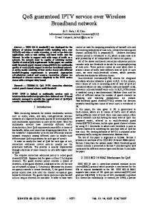
(a) Connectivity Graph Fig. 1.
(b) Logical Connection Graph
Example Mesh Network
achieves high raw bit rates by using an OFDM based physical layer in the 5GHz license-exempt band. However, even with the high bit rates, 802.11a is not the most appropriate protocol for mesh networks because of high overhead and the unfairness that can affect TCP flows. We first describe the 802.11 DCF and then show why mesh networks need a new MAC protocol. 802.11 DCF uses collision avoidance to decrease the number of packet collisions in the network. Collision avoidance is based on the use of the basic procedure. In the basic procedure, the transmitter senses the channel until it becomes free. Once the channel is free, the transmitter waits for a duration of DIFS seconds and then calculates an additional “back-off” waiting time. The back off time is chosen randomly in the interval of [CWmin, CWmax] × aSlotTime seconds. After waiting for the end of the back-off time the transmitter sends a packet. In addition to the basic procedure, the nodes also have the option of using RTS-CTS-ACK exchanges. The RTS-CTS exchange starts after the transmitter has performed the basic procedure. The exchange is used to announce to neighbouring nodes that a transmission will take place. As a part of the exchange, the transmitter announces how long the transmission will last, so that the neighbouring nodes can set their virtual sensing timers. The ACK packets are included to ensure that the sender knows when its packet is received successfully. Using the values for timing constants listed in the standard [11], we find that the overhead RTS-CTS-ACK exchanges is 318µs per packet.
A. Related Work In [8], the authors propose an overlay MAC layer for 802.11 mesh networks. The overlay uses admission control to ensure that real-time flows receive a good quality of service, however the overlay itself does not improve the performance of the underlying 802.11 hardware. A different MAC overlay layer is proposed in [9]. This overlay improves the performance of 802.11 with loose TDMA synchronization. Even though the overlay MAC in [9] uses TDMA-like access to the wireless channel, it still only provides best effort service. In contrast, our approach uses small frame size and synchronization from the 802.16 protocol to provide guaranteed access to the channel. The embedded 802.16 used in this paper can be used with software based MAC platforms like [10]. In that software platform, 802.11 operation is modified as far as the network driver will allow it, so that the network cards behave almost as a software TDMA radio transceiver. Our approach is also appropriate in the more general case, where the specific hardware used in [10] is not available, since our embedding does not make any assumptions about 802.11 hardware beyond what is specified in the standard [11].
A. Performance of DCF with TCP traffic load Fig. 1 shows a small mesh network that we will use throughout the paper to examine the performance of the MAC protocols we are comparing. We chose to examine a three node network to illustrate the points most relevant to our paper. However, all of our conclusions extend to larger size networks as well. Left side of the figure shows the actual connectivity in the network with the dashed lines. If two nodes are connected with dashed lines, they can hear each others transmissions. The right side of the figure shows the paths in the network. Since the network is static it does not make sense to use any ad-hoc network routing protocols such as AODV [12] or DSR [13], rather the routes are chosen with a simple minimum-hop distance criterion. This is in-line with the implementation of mesh networks, that use OSPF [3], [5].
II. 802.11 D ISTRIBUTED C OORDINATION F UNCTION Current wireless mesh networks use IEEE 802.11a protocol to implement node-to-node connectivity [3], [11]. 802.11a 2
Instanteneous Throughput
Data
Guard Symbol
250
Throughput (kbps)
Guard Symbol
Flow 1 Flow 2 Flow 3
Guard Symbol
Control Minislot
300
200
Fig. 3.
Structure of 802.16 MAC Control Minislot
150
transmissions can be aligned by the length of OFDM symbols. IEEE 802.11a also uses OFDM, but to achieve high data rates. Second, we describe the 802.16 MCF and show its performance.
100
50
A. 802.16 Physical Layer
0 0
20
40
60
80
IEEE 802.16 uses OFDM in the license-exempt 5GHz frequency band. OFDM transforms blocks of bits into constant duration symbols carried on a set of frequency orthogonal pilot carriers. The bandwidth of the final signal is the frequency range occupied by all of the pilot carriers. The duration of each symbol, TSymbol , depends on the bandwidth of each subcarrier, which determines time needed to transmit an unguarded OFDM symbol.
100
Time (s)
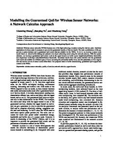
Fig. 2.
TCP Throughput over 802.11a MAC
The traffic in the network is setup the way it would be in a typical mesh network with the three mesh nodes 1, 2, and 3 connecting to the base station (node 0). We have setup three TCP connections, one for each mesh node, that transfer a large file (5Mb) using the FTP protocol. Fig. 2 shows the instantaneous throughput of the three flows with respect to time. The MAC protocol used in the simulation is 802.11a, which we have added to the simulator by modifying 802.11b protocol available with ns2. All of the links in the network use BPSK-1/2 modulation for raw bit rates of 6.0Mbps. The flow number corresponds to the identification of the node that initiates the traffic. Flows 1, 2, and 3 start at times 5, 10, and 15 from the beginning of the simulation. The figure shows the unfairness and unpredictability of service that happens with 802.11. This is similar to previously reported findings about 802.11 [4]. When flow 3 starts at time 15 seconds it does not get any service. At around time of 35 seconds into the simulation, when flow 2 finishes all of its packet transmission, flow 3 takes over the channel. The problems shown in Fig. 2 are due to the collisions in the wireless channel. We will show later in the paper that by using 802.16 MCF embedded in 802.11a broadcast packets, all of these problems are resolved since the collisions are removed.
B. 802.16 Frame Structure TDMA MAC protocols organize time slots into frames for two reasons. First, the frame boundaries are used to synchronize the mesh nodes. Second, the frame structure allows the division of control and data traffic into subframes. The position of the control subframe is known to all mesh nodes, so the timing of all control messages is well known. In the data subframe, time slots are grouped into minislots of equal length, and then assigned to logical links between the mesh nodes. The 802.16 MCF controls the transmission schedules in the control and data subframes. The control subframe is logically represented by a single channel, so a transmission schedule for the control subframe maps minislots to nodes. On the other hand, the data subframe has many logical channels each representing a directional connection between two mesh nodes, so a transmission schedule in the data minislots to links. The frame is divided into the control subframe and the data subframe. The size of the 802.16 control subframe is 7×MSH-CTRL-LEN TDMA symbols, where MSH-CTRL-LEN is a parameter left up to the network operator. The control subframe is divided into MSH-CTRL-LEN minislots each occupied by a single control packet. The timing structure of the control packet is shown in Fig. 3. Three of the symbols are used to guard the packet, while the other four carry the payload. The packets in the control frame are sent at the lowest modulation, making the largest possible size for a control packet 48 bytes. The data subframe is also divided into minislots with a fixed length. The length of data minislots is determined by dividing the number of OFDM symbols in the data subframe by 256. The timing structure of data packets is similar to the structure of control packets, except that the data portion is variable.
III. 802.16 M ESH C OORDINATION F UNCTION IEEE 802.16 is a TDMA based MAC protocol [6], built on a Time Division Multiplexing (TDM) physical layer. In TDM physical layers, the time is divided into time slots of equal length, and during each time slot a block of bytes is broadcast. In TDM based MAC protocols, the time slots are grouped into frames of equal length. The frames are then repeated over time. IEEE 802.16 MCF specifies how the time slots in each frame are divided among the nodes. First, we describe the physical layer used in 802.16 and compare it to the physical layer used in 802.11a. 802.16 uses OFDM to implement the TDM physical layer; since all 3
Instanteneous Throughput
For example, if the minislot size was 4 OFDM symbols, the smallest data packet size at the lowest modulation, would be 12 bytes, the next size for a data packet is 24 bytes for two minislots, and then 36 bytes for three minislots.
160
Flow 1 Flow 2 Flow 3
140 120
Throughput (kbps)
C. 802.16 Scheduling The control subframe transmission scheduling is specified by the standard. However, the standard leaves open how transmission schedules in the data subframe are determined and only specifies the mechanisms by which transmissions schedules in the data subframe are announced. We now describe the centralized and decentralized scheduling protocols used to announce the transmission schedules in the data subframe. 1) Centralized Scheduling Protocol: The nodes monitor the traffic demand from their subscribers and use this information to request bandwidth from the base station. The base station uses the requests to calculate the schedule for each link in the network. The schedule is then transmitted as a tree of links that the nodes should use to send packets to the base station, together with the length of time each node should transmit in a frame. The schedule is flooded through the network, so that all mesh nodes know the entire transmission schedule. 2) Decentralized Scheduling: The nodes negotiate the starting minislot and duration for each link. The protocol uses handshakes to ensure all neighbouring nodes are aware of the transmission schedules.
100 80 60 40 20 0 0
20
40
60
80
100
Time (s)
Fig. 4.
D. Performance of 802.16 MCF with TCP Traffic Load We implemented 802.16 MAC and physical layers in ns2 and used this implementation to compare the performance of 802.16 to 802.11a. In our simulation, we use the same scenario used in Section II-A. The physical layer is using 20MHz of bandwidth per channel giving an OFDM symbol length of 25µs. The frame length is 10ms giving a total of 400 OFDM symbols per frame. All links are using modulation of QPSK-1/2 which has similar raw bandwidth to the BPSK1/2 modulation of 802.11a. The OFDM symbols are equally divided among the six links in the network (Fig. 1b) giving each link equal bandwidth. Fig. 4 shows the instantaneous throughput of the three connections. First, we observe that the instantaneous throughput is fairly stable. There are no major fluctuations of throughput compared to the instantaneous throughput shown in Fig. 2. Second, we observe that flow 3 does not interfere with flows 1 and 2. Third, we observe that when both 1 and 2 are active, they are sharing the link without interfering with each other. All three observations are easily explained by the fact that the channel is shared with collision free TDMA. We note that the peak throughput in Fig. 4 is lower than the peak throughput in Fig. 2. This is because the bandwidth of each link is limited by the number of OFDM symbols allocated to that link. In effect, there is no multiplexing of the MAC connections sharing the channel that can allow MAC flows to use the unused portion of bandwidths of other MAC flows. However, this is offset by the fact that the links have guaranteed QoS provided by the channel, which is not possible with 802.11.
Fig. 5.
Throughput with 802.16a MAC
Embedding 802.16 PDU over 802.11a
IV. E MBEDDED 802.16 MCF OVER 802.11 H ARDWARE We proposed embedding 802.16 MAC packet data units (PDUs) into 802.11a MAC broadcast packets in [1]. In that work, we have shown that the RTS-CTS-ACK exchanges are not necessary since 802.16 MCF coordinates the nodes, and acknowledgments are a part of the 802.16 protocol. We have shown in Section II that the RTS-CTS-ACK exchanges decrease the efficiency of the 802.11a protocol, so removing them actually makes our protocol more efficient than the 802.11a DCF. Fig. 5 shows the embedding of the 802.16 packets into the 802.11a broadcast packets.1 The embedding assumes that the back-off time is always one. For this to be true, we need to set CWmin = CWmax = 1.2 The length of the PLCP preamble includes 12 training symbols as well as one OFDM symbol that carries the PLCP header, for a total of 13, 4µs, symbols [16]. 802.11 headers include 2 bytes for the symbol field 1 It is possible to embed the packets in conjution with the sub-network access protocol (SNAP) [14]. However, this is not necessary under Linux because the kernel allows the definition of custom ethernet types, so we opted to use an embedding with a smaller size, i.e. without the SNAP sub-header. 2 For real implementations, this assumptiondepends on the firmware support. For example, the Intel PRO/Wireless 2900bg cards allow this change [15].
4
(specific to 802.11a), as well as 24 bytes for 802.11 MAC headers [11], [16]. The transmission time required to transfer L bits of the 802.16 embedded packet (Fig. 5) is given by : � � 214 + L 802.11 Ttran = 95µs + × 4µs, (1) 802.11 rmod
Bandwidth vs. SDU Size 1 0.9 0.8
BW (Mbps)
0.7
where 95µs is the total time required for the DIFS and aSlotTime times and the time required for 13 symbols of PLCP preamble, 214 bits of overhead comes from 802.11a headers (208 bits) and the minimum of 6-bit pad, and the 802.11 rmod is the number of data bits in an 802.11 OFDM symbol. The bottom part of Fig. 5 shows how 802.16 MAC interprets the embedded transmission. We set the minislot duration TMS = 16µs, so each minislot corresponds to four 802.11a OFDM symbols.3 We modify the settings for the 802.16 MAC protocol to make the front guard time 9 minislots and the back guard time one minislot (Fig. 3). We chose the value of 9 for the front guard because that is longer than the time required to transmit all of 802.11a overhead with any modulation rate. The back guard symbols are the minimum required to transmit 802.11a padding. The 802.16 overlay MAC layer calculates the transmission time as: � � �� P + 64 802.11 802.16 + 10 × 16µs > Ttran , (2) Ttran = 802.16 rmod
0.5 0.4 802.16 (embedded) 802.16 (10MHz) 802.16 (20MHz) 802.11a (DCF) 802.11a (broadcast)
0.3 0.2 0.1 0
0
500
1000 SDU Size (bytes)
1500
2000
(a) BPSK-1/2 Bandwidth vs. SDU Size 3
2.5
BW (Mbps)
2
1.5
1
802.16 where rmod is the number of data bits in an 802.16 symbol, P is the size of the network layer packet in bits and 64 bits of overhead come from the 802.16 MAC headers. The transmission time seen by 802.16 MAC is strictly greater than the time actually required to transmit the packet over 802.11a ensuring collisions do not occur. If a corrupted packet is received by a node, the DCF on the receiver node selects a timeout of TEIFS = 658µs before the basic procedure can start on that node. This timer is cancelled if another packet is received correctly before the timer expires. The embedding module always checks if the previous transmission was successful before transmitting a new packet, and it cancels all packets requested by the 802.16 module during active transmissions. This procedure makes sure that if an EIFS timer is on at a transmitter node, the packets from that node do not get delayed past the start time of the next transmitting node. At most one packet from any transmitter will colide with packets from another node. If a collision happens, the DCF back-off mechanism cannot increase CWmax more than 1 so (2) will still hold.
802.16 (embedded) 802.16 (10MHz) 802.16 (20MHz) 802.11a (DCF) 802.11a (broadcast)
0.5
0
0
500
1000 SDU Size (bytes)
1500
2000
(b) QPSK-3/4 Fig. 6.
Data Rates of embedded 802.16
and the sender and receiver use RTS-CTS-ACK exchanges. We observe that this is a very optimistic view of the 802.11 bandwidth (Fig. 2). Fig. 6a shows the achievable bandwidth when the modulation is BPSK-1/2. First, we observe that the achievable bandwidth of the embedded scheme is comparable to the bandwidth that can be achieved using 802.16 hardware. The achievable bandwidth of the embedded scheme is always less than what can be achieved with 802.16 hardware operating at 20MHz, and more than the bandwidth of 802.16 hardware operating at 10MHz. This corresponds to the fact that the actual symbol duration is 16µs in the embedded scheme compared to 12.5µs and 25µs for 802.16 hardware operating at 20MHz and 10MHz, respectively. Second, we observe that the achievable bandwidth is higher than the achievable bandwidth of 802.11a DCF. This is because the embedded scheme has less overhead even with the added padding. In fact, the 802.11a bandwidth shown in the figure is a very optimistic view of 802.11a bandwidth since it
A. Bandwidth of the embedded 802.16 Fig. 6 compares the bandwidth of the embedded transmissions to the bandwidths that can be achieved using other schemes discussed in this paper. The bandwidth is defined as the number of bits divided by the actual time required to transmit those bits. The bandwidth for 802.11a DCF is found by assuming that there are no collisions in the channel 3 This
0.6
minislot duration maps one 802.16 OFDM symbol to TMS .
5
Instanteneous Throughput
does not take into account collisions, nor regular back-offs. In practice, as we have shown in Fig. 2, the throughput of 802.11a is much lower, especially with multiple active connections. Third, the achievable bandwidth of the embedded 802.16 is lower than the bandwidth that could be achieved by using broadcasts only. This is due to the padding of 802.11a broadcast packets. Again, the bandwidth shown for the 802.11a broadcast is optimistic since we are not accounting for backoff time. Nevertheless, the difference in bandwidth is not significant. Fig. 6b shows the achievable bandwidth when the modulation is QPSK-3/4. We observe for lower packet sizes (less than 400 bytes), the embedded scheme performs worse than 802.16 at 10MHz. However, 802.16 allows packing of smaller SDUs into a larger PDU, which should make the embedded scheme perform as shown in the part of the figure where packet sizes are larger.
160
Flow 1 Flow 2 Flow 3
140
Throughput (kbps)
120 100 80 60 40 20 0 0
20
40
60
80
100
Time (s)
Fig. 7.
B. Performance of embedded 802.16 with TCP Traffic Load We implemented the embeding of 802.16 MAC packets in ns2 and we used the 802.11a MAC layer implementation to find the performance of the embedded scheme. In our simulation, we use the same scenario used in Section II-A. The frame length is 10ms giving a total of 625 OFDM symbols per frame. All links are using QPSK-1/2 modulation as in Fig. 4. The OFDM symbols are equally divided among the six links in the network (Fig. 1) giving each link equal bandwidth. Fig. 7 shows the instantaneous throughput of the three connections. First, we observe that the instantaneous throughput is almost identical to the throughput of Fig. 4, showing that the embedding works and there are no collisions. We do not see higher peak throughput in Fig. 7 even though the achievable bandwidth of the embedded scheme is higher than the achievable bandwidth of 802.16 at 20MHz because the bandwidth of each link is limited by the number of OFDM symbols allocated to that link, and not the peak bandwidth on the link.
Throughput of embedded 802.16
R EFERENCES [1] P. Djukic and S. Valaee, “802.16 MCF for 802.11a based mesh networks: A case for standards re-use,” in 23rd Queen’s Biennial Symposium on Communications, 2006. [2] J. Camp, J. Robinson, C. Steger, and E. Knightly, “Measurement driven deployment of a two-tier urban mesh access network,” Rice University, Technical Report TREE0505, December 2005. [3] Nortel Networks, “Wireless mesh network - extending the reach of wireless LAN, securely and cost-effectively,” http://www.nortelnetworks.com/solutions/wlan/, November, 2003. [4] S. Xu and T. Saadawi, “Does the IEEE 802.11 MAC protocol work well in multihop wireless ad hoc networks,” IEEE Communications Magazine, vol. 39, no. 6, pp. 130–137, June 2001. [5] IEEE, “802.11 TGs MAC enhacement proposal,” IEEE, Protocol Proposal IEEE 802.11-05/0575r3, September 2005. [6] “IEEE standard for local and metropolitan area networks part 16: Air interface for fixed broadband wireless access systems,” 2004. [7] M. Cao, W. Ma, Q. Zhang, X. Wang, and W. Zhu, “Modeling and performance analysis of the distributed scheduler in IEEE 802.16 mesh mode,” in MobiHoc, 2005, pp. 78–89. [8] H. Wu, Y. Liu, Q. Zhang, and Z.-L. Zhang, “SoftMAC: Layer 2.5 collaborative MAC for multimedia support in multi-hop wireless networks,” IEEE Transactions on Mobile Computing, to Appear. [9] A. Rao and I. Stoica, “An overlay mac layer for 802.11 networks,” in MobiSys, 2005, pp. 135–148. [10] M. Neufeld, J. Fifield, C. Doerr, A. Sheth, and D. Grunwald, “SoftMAC—flexible wireless research platform,” in HotNets, 2005. [11] “IEEE standard for local and metropolitan area networks part 11: Wireless lan medium access control (MAC) and physical layer (PHY) specifications,” 1999. [12] C. E. Perkins and E. M. Royer, “Ad hoc on-demand distance vector routing,” in Proceedings of the 2nd IEEE Workshop on Mobile Computing Systems and Applications, New Orleans, LA, February 1999, pp. 90–100. [13] D. B. Johnson and D. A. Maltz, “Dynamic source routing in ad hoc wireless networks,” in Mobile Computing, ser. The Kluwer International Series in Engineering and Computer Science, Imielinski and Korth, Eds. Kluwer Academic Publishers, 1996, vol. 353. [Online]. Available: http://athos.rutgers.edu/$\thicksim$imielins/book.html [14] “IEEE standard for local and metropolitan area networks: Overview and architecture,” 2001. R [15] “Intel PRO/Wireless 2200BG driver for linux,” http://ipw2200. sourceforge.net/. [16] “IEEE standard for local and metropolitan area networks part 11: Wireless LAN medium access control (MAC) and physical layer (PHY) specifications high-speed physical layer in the 5 GHz band,” 1999.
V. C ONCLUSION We have presented a method that allows 802.16 MCF to be used for TDMA data transmissions in 802.11a mesh networks. The method works by embedding 802.16 packets into 802.11a broadcast packets with padding so that all transmissions can be aligned on 802.16 frame boundaries. Our method significantly decreases the overhead inherent in RTS-CTS-ACK exchanges, which are a part of the 802.11 DCF. At the same time, our method removes collisions from the channel because the nodes are communicating in 802.16 TDMA fashion. We have used ns2 simulations to show that if our method is used in 802.11a based mesh networks, the mesh networks can give predictable, guaranteed service. Our method requires only software changes on the nodes using 802.11a for mesh communications. This means that the mesh networks installed with 802.11a hardware today can be upgraded with a software patch to take advantage of 802.16 MCF and do not have to wait for hardware upgrades to 802.11s. 6