Towards the Formalization of a Reusability Framework for Refactoring Rodrigo E. Caballero1 and Steven A. Demurjian, Sr.2 1
United Technologies Research Center, East Hartford, Connecticut 06108, U.S.A.
[email protected] 2 University of Connecticut, Department of Computer Science and Engineering, Storrs, Connecticut 06269-3155, U.S.A.
[email protected]
Abstract. As industry and academia embrace component and objectbased design models, programming languages, technologies, and tools, they are outpacing our ability to formally define models and frameworks supporting organization and domain specific reuse. For software engineers to accurately assess potential and actual reuse of software artifacts, we must transition from ad-hoc reuse to a evaluative paradigm that achieves reuse of an organization’s current and future products. Towards this goal, our previous work has provided a framework for reusability assessment of components and classes via metrics and refactoring guidelines. In this paper, we work towards the formalization of this reusability framework. Our objectives and contributions are: a set of properties for the assumptions of the reusability framework; the formalization of class coupling, class generality, and related class concepts which underlie reuse assessment and refactoring; a reusability improvement factor to capture refactoring gain (or loss); and a refactoring algorithm for improving reusability.
1
Introduction
The improvement of the software development process through the maintenance and utilization of large inventories of reusable software components has been advocated since the late 1960s [6]. The long articulated benefits of reducing risk, limiting development and maintenance costs, improving time to market, increasing quality and reliability, improving interoperability, supporting rapid prototyping, [1, 4, 17, 21, 23], etc., while touted, are difficult to prove in practice, despite our increased emphasis on component and object-based design models and programming languages (and associated technologies and tools). In the literature, reusable software has been characterized using two metrics [22]: actual reuse, the number of times that a software component has been previously used, and reusability, which estimates the relative applicability for reuse of a component in a future setting. This reusability, or reuse potential, is often targeted at domain-and-organization-specific reuse, which can total up to 80% of a product or application [7, 10]. Our interests are in domain-and-organization-specific
reuse, which shifts costs to the earliest stages of the design/development process, and represents a long-term investment in reuse [20] to support entire product families of today and tomorrow. Towards that end, there must be a focused effort to develop, guidelines, standards, models, and metrics for reuse [11]. To support the process of improving reuse potential, we have developed an integrated reusability metric, framework, and tool [12–14]. In this work, we provide an annotation technique by which a software engineer can define related classes/components that are expected to be used together in future applications, marking them to indicate the reusability level, which can range from the general (able to solve problems in multiple contexts) to the specific (single use - will not be reused). For example, in a retailing application, a supplier would track a general Item (reusable in many business contexts), a auto-parts supplier would have a less general AutomotiveItem (reusable in that context only), and individual retailers would have a specific WalmartItem (useable only by that specific company). Given classes/components that have been annotated with reusability levels, our reusability metrics can be iteratively utilized to objectively classify and measure dependencies (couplings) within and among classes/components, identifying couplings that promote and hinder future reuse. For couplings that hinder reuse, ad-hoc refactoring guidelines are suggested, with a projected improvement in reusability. Our major objective in this paper is to formalize the majority of our prior work [12–15], to yield a comprehensive framework that automates reusability assessment and refactoring. Specifically, the characteristics proposed in [15], namely, coupling between classes, and reusability level, can be modeled as relations, which are expressed as zero-one matrices, to facilitate their computational implementation, and provide a mathematical framework for the reusability analysis. Further, in this paper, we propose a reusability improvement factor that reflects the impact (positive or negative) on the application’s reuse potential based on different refactoring operations that can be applied to a component/objectbased application. Using this factor, we have significantly extended the analysis proposed in [15], by defining an algorithm for the improvement of the reuse potential of an object-oriented application. The proposed algorithm can be easily and efficiently implemented and integrated into the DRE tool (see [15] and http://www.engr.uconn.edu/˜steve/DRE/dre.html). The remainder of this paper is organized as follows. Section 2 mathematically expresses the basic concepts of an object-oriented application. Section 3 presents the assumptions of the reuse model, focusing on generality and related classes/components, and reviews a set of properties for the reuse framework. Section 4 contains a detailed discussion on couplings among classes, the transition from couplings that hinder reuse to ones that promote reuse, and a mathematical formulation that is the basis of the proposed reusability improvement factor. Section 5 describes the refactoring process via a formal algorithm that results in reusability improvement, as illustrated via an example. Section 6 discusses related work. Finally, Section 7 presents the conclusions, and ongoing and future research.
2
Object-Oriented Application Model
In this section, we define a model for an object-oriented application that supports the formalizations and algorithms in the remainder of the paper. Definition 1: Let an object-oriented application S be the 3-tuple (C, ΓI , Γm ) where – C is the set of classes, where each class Cp contains a set CpM of methods mi ∈ M such that each method mi belongs to only one class – ΓI is the set of pair-wise inheritance relations of classes in C ΓI = {(Cp , Cq ), Cp ∈ C ∧ Cq ∈ C | Cp
extends
Cq }
(1)
– Γm is the set of pair-wise coupling among methods Γm = {(mi , mj ), mi ∈ CpM ∧ mj ∈ CpM | mi
uses
mj }
(2)
Using this definition, we define coupling relations between classes [16]. Definition 2: Two classes Cp and Cq are pair-wise coupled, when there is at least one method mi ∈ CpM that invokes a method mj ∈ CqM , as represented by the relation ΓC : ΓC = {(Cp , Cq ) | ∃mi ∈ CpM ∧ ∃mj ∈ CqM ∧ (mi , mj ) ∈ Γm }
(3)
Note that this assumes that classes do not have direct access to attributes defined in other classes, i.e., access occurs via get/set methods. The relations ΓI , ΓC , and Γm can be represented using zero-one matrices, which is convenient for the computation implementation of the model. The set of classes C and the coupling relations ΓC define a directed graph structure where the classes in C are nodes, and the ordered pairs in ΓC are edges. The pair-wise definitions of the relations ΓI , ΓC and Γm do not hold the property of transitivity, and for that reason such definitions might seem counter intuitive. Despite this fact, the definitions proposed here greatly facilitate the direct calculation of ΓI , ΓC and Γm from source code. This is a desirable feature of the model when it is implemented in a tool such as the one reported in [15]. Coupling and inheritance relations among groups of classes and methods are transitive relations that are modeled by the connectivity relations ΓI∗ , ΓC∗ , and ∗ Γm . These relations can be efficiently computed using Warshall’s Algorithm [18].
3
Reuse Framework
In this section, we review the basic concepts and critical assumptions of the framework for analysis and measurement of object oriented reusability proposed in [12–14] and later extended in [15]. The reuse framework is based on two characteristics: class reusability assessment and relations among classes. As proposed in [13, 14], the reusability of a class can be either general or specific. A general
class is one that is expected to be reused in future applications, while a specific class is only applicable in the current application. For example, in a retail application, an Item class to track products would be the general to all retail applications, while a WalmartItem class, a descendant of Item, would contain characteristics that are store specific. In a later publication [15], the model was extended to accommodate levels of generality, and, as such, better exploit the reuse potential of classes. For example, there could be a range of generality for classes that range from Item to DeptStoreItem to DiscountStoreItem to WalmartItem, clearly demonstrating four different reusability levels. This leads to the following: Definition 3: The reusability level of a class Ci is denoted by GCi , where GCi = 0 when Ci is the most general class in the application, and GCi = N (N > 0) when Ci is the most specific class in the application. Further, given a set of n classes C, the class generality vector G is a vector such that the i-th component GCi is the reusability level of the class Ci . Relations among classes is a characterization by the software engineer of classes that are expected to be reused together in future applications. For example, in the retail application, the Item class and ItemCollection class (the set of all Items) may be related, if a software engineer decided that the two classes were always expected to be reused together. More often than not, related classes are coupled, as captured in ΓC . Definition 4: Two classes, Cp and Cq that are related can be defined by the ΓR relation as follows: ΓR = {(Cp , Cq ), Cp ∈ C ∧ Cq ∈ C | Cp
reused with
Cq }
(4)
Class reusability and relations among classes are an important part of a framework for reusability analysis. To augment these definitions, we propose a set of properties that represent the assumptions upon which the reuse framework is constructed. Property 1. The parent of a class is equally general or more general than its children. (Cp , Cq ) ∈ ΓI ⇒ GCp ≥ GCq
(5)
By definition, the inheritance hierarchy relates classes where the children have more specific descriptions that build and extend on the parents. Since the children extend on the parents, the children have at least the reusability level of the parents, plus optional specific method(s). Consequently, the generality of the ancestors of a class has to be equally or more general than the class itself. For example, WalmartItem, which extends Item, is less general since it intended to be used by only that specific company. The levels of reusability in an inheritance hierarchy defines a partial order relation.
Property 2. The reusability level of a class is equal to the reusability level of the least reusable coupled class. The reusability level of a class reflects the extent to which the class is expected to be reused in future applications. Given two classes Cp and Cq with reusability levels GCp and GCq such that (Cp , Cq ) ∈ ΓC , the following two situations are relevant: – Class Cp is more specific than class Cq (GCp > GCq ), in which case Cp is the least reusable class. – Class Cp is more general than class Cq (GCp < GCq ). Since there is a coupling from Cp to Cq , Cp is dependent on specific features of Cq that will condition the reusability of Cp to situations when Cq is reusable. Thus, the reusability level of Cp is equal to the reusability level of Cq , which is the least reusable class. Property 3. Classes that do not contribute to the functionality of a component have a negative impact on reuse. The reuse of classes that do not contribute to the functionality of the reusable component or have only a small fraction of their methods that contribute to the functionality of the reusable component, have a negative impact on the application that reuses the component. Classes that do not contribute to the functionality increase the size of the application without any real benefit. Longterm, we intend to be able to recognize such situations to alert the software engineer when they occur. Property 4. Couplings between unrelated classes hinder reuse. From the definition of related classes, we derive that unrelated classes are not intended to be reused together in future applications. If there are dependencies among unrelated classes, the coupled classes must be reused together in order for the system to function properly. This contradicts the intention of the software engineer not to reuse the components together. Therefore, dependencies between unrelated classes are undesirable.
4
Reusability Analysis
From the definitions of generality/related and properties in Section 3, we can draw conclusions regarding the way to assess reusability improvement by focusing on the reusability level and couplings that exist among classes. This will lead us to a methodology that is based on an initial assessment of the couplings, and a criteria to evaluate the impact on reuse of different refactoring operations to improve reusability, as we will examine in Section 5.1. As discussed in Section 3 (see Definition 3), software engineers label or mark their classes with a reusability level, that denotes the reuse potential of the class. To simplify the discussion, assume that there are only two levels of generality,
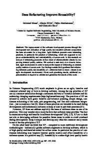
G and S; if there are multiple reusability levels, one can focus on only two levels at a time. Between these two reusability levels there are four types of couplings: a G class can depend on another G class, a G class can depend on a S class, a S class can depend on a G class, and a S class can depend on another S class. These dependencies take the form of a method call, an instance variable reference, etc. For the purposes of this paper, we use the 8 coupling types introduced in [12–15], which are classified based on whether they are among related classes (Types 1, 3, 5, or 7) that are expected to be reused together, or among unrelated classes (Types 2, 4, 6, and 8). Type 1: G → G among related classes. This coupling is an asset to reuse, and the objective is to increase these couplings. Type 2: G → G among unrelated classes. This coupling is undesirable since the source and destination are not expected to be reused together. To improve reuse, one could move both the source and destination to Specific descendant classes. Type 3: G → S among related classes. This coupling is undesirable, since the General class (to be reused) depends on a class which is not expected to be reused. To improve reuse, one could move the source to a Specific descendant or the destination to a General ancestor. Type 4: G → S among unrelated classes. This coupling is undesirable since the source is expected to be reused while the destination is not. To improve reuse, one could move the source to its Specific descendant class. Type 5: S → G among related classes. This coupling does not hinder reuse since the source of the coupling is not expected to be reused. However, one could improve reuse by moving the source to a General ancestor. Type 6: S → G among unrelated classes. This coupling does not hinder reuse since the source of the coupling is not expected to be reused. There is no way to improve reuse in this case. Type 7: S → S among related classes. This does not hinder reuse since the source of coupling is not expected to be reused. However, one could improve reuse if both the source and destination are moved to their General ancestors. Type 8: S → S among unrelated classes. This is not a hindrance to reuse, rather, it represents the desired situation for couplings between unrelated classes; they need to be among the Specific classes. Given the eight different coupling types, from a reusability-assessment perspective, our objective is to provide a concrete mechanism that can be utilized to automatically refactor a design in order to improve reuse. To accomplish this, it is important to track the couplings, in order to assess the impact on reuse when a coupling is moved from one coupling type to another. For example, a coupling transitioned from Type 3 to Type 1 moves a coupling that hinders reuse (Type 3) to one that promotes reuse (Type 1). To illustrate the impact on reuse of the transitions between different coupling types for related and unrelated classes, the state diagrams in Figure 1 are provided. The states in the figures represent the
coupling types proposed in [13, 14], and the numbers in the transitions represent the impact on the reusability of the system when transitions occur between coupling types, +1 representing positive impact - promotes reuse, −1 representing negative impact - hinders reuse, and 0 representing no impact. In the case of related classes, the transitions between coupling types promote and/or hinder reuse of the application as follows: – Couplings from general to specific classes hinder the reuse of components. In the case of related classes, from Property 2, reusability of the general class is limited by the coupling to the more specific class. For this reason coupling Type 3 is undesirable for reuse, and consequently transitions to coupling Type 3 hinders reuse, as shown by the arrows labeled A/-1 and B/-1 in Figure 1 (a). In contrast, the transition in the opposite direction promotes reuse, as shown by the arrows labeled A/+1 and B/+1 in Figure 1 (a). – Couplings between general classes that are related, represents valuable design knowledge that can be reused [15]. For this reason, transitions to couplings Type 1 promote reuse, as shown by the arrows labeled B/+1 and C/+1 in Figure 1 (a). In contrast, the transition in the opposite direction hinders reuse, as shown by the arrows labeled B/-1 and C/-1 in Figure 1 (a). – In the case of couplings between related classes in which the source class is specific —such as Type 5 and Type 7— from Property 2 the reusability is not affected by the coupling to another class. Coupling Type 5 and Type 7 are acceptable, but can be improved by transitioning to Type 1. For this reason, transitions between Type 5 and Type 7 have no impact on reuse, as shown by the two D arrows labeled with zeros in Figure 1 (a). Note that in Figure 1 (a), we have not shown diagonal lines, i.e., transitions from Type 1 to/from Type 7 and Type 3 to/from Type 5. This is since these transitions can be accomplished in two steps. For example, going from Type 7 to Type 1 (change both source and destination from specific to general) can be accomplished by going from Type 7 to Type 5 to Type 1, for a net gain of +1. Note also that the process in not symmetric; from Type 7 to Type 3 to Type 1 has no gain. This was intentional, to force the path the would have a positive gain. In going from Type 7 to Type 3, there is a loss (-1). If the software engineer did not make the second move to Type 1, there would be a net loss, which doesn’t occur in the other path, since Type 7 to Type 5 is a zero transition. Correspondingly, transitions between coupling types when the classes are unrelated promote and/or hinder reuse of the application as follows: – Based on Property 4, unrelated classes hinder reuse. Coupling types in which the source class is general are particularly undesirable. From its definition, a general class is expected to be reused in future applications, so couplings to a non-related class result in the reuse of unrelated classes every time the source class is reused. In other words, the coupling to a non-related class diminishes the reusability of the source class. Consequently, transitions from couplings Types 6 and Type 8 to couplings Types 2 and 4, respectively, hinders reuse, as shown by the arrows labeled H/-1 and J/-1 in Figure 1 (b),
while transitions in the opposite direction promote reuse, as shown by the arrows labeled H/+1 and J/+1 in Figure 1 (b). – Transitions from couplings Type 2 to Type 4 hinders reuse, as shown by the arrow labeled I/-1 in Figure 1 (b). From Property 2, coupling Type 4 not only forces the joint reuse of unrelated classes, but also diminishes the reusability of the general class. All other transitions between unrelated classes have no impact on reuse, as shown by the I/0 arrow and the two K arrows in Figure 1 (b). Again, as with the related case, we do not at this time consider diagonal transitions, namely, Type 2 to/from Type 8 and Type 4 to/from Type 6. These diagonals and their gain or loss can be attained in a similar fashion to the previous discussion in the related case. º Type 3 G→S ¹
6
+1
A
· +1 B
¾ ¸ −1
−1
−1
? º Type 7 S→S ¹
º · º ·0 - Type 1 Type 4 ¾ I G→G ¸ G→S ¹ ¹ ¸ −1 6 6
·0 ¾ D
¸0 (a)
C
+1
? º Type 5 - S→G ¹
+1
H
+1
−1
? · º Type 8 S→S ¸ ¹
º · - Type 2 G→G ¸ ¹ 6
·0 ¾ K
¸0
J
−1
? º
·
Type 6 - S→G ¹
¸
(b)
Fig. 1. Coupling Transitions for (a) Related Classes and (b) Unrelated Classes.
The coupling type transition matrix τ = [τuv ] is the matrix that represents the state diagrams, where:
τuv
+1 = −1 0
if the transition from coupling type u to coupling type v has a positive impact on reuse if the transition from coupling type u to coupling type v has a negative impact on reuse if the transition from coupling type u to coupling type v has no impact on reuse
Then, from the state diagrams in Figure 1, τ = [τuv ] is:
0 0 −1 0 −1 0 0 0 0 0 0 −1 0 +1 0 0 +1 0 0 0 0 0 +1 0 0 0 0 0 0 0 0 +1 τ = +1 0 0 0 0 0 0 0 0 −1 0 0 0 0 0 0 0 0 −1 0 0 0 0 0 0 0 0 −1 0 0 0 0
(6)
Note that τ = [τuv ] is used in Section 5 to evaluate the reusability improvement factor, ∆ρ, to determine whether a refactoring operation promotes or hinders the reuse of the application.
5 5.1
Refactoring Algorithm and Example The Refactoring Process
In this section, we present an algorithm to improve the reuse potential of an application, which is loosely based on the reusability analysis in [15]. The algorithm is comprised of a series of steps. Steps 1, 2, and 3 initialize the different vectors and matrices as defined in Sections 2 and 3, while Steps 4 through 8 represent an iterative process that is undertaken until a software engineer is satisfied with the reusability results. 1. Identify Reuse Potential Identify the classes that would potentially be reused in future applications. Reusable classes are characterized with varying reusability levels (see Section 3 and Definition 3), based on domain knowledge and information on the application. This process defines the class generality vector G. 2. Calculate the Couplings Determine the actual couplings among the methods that comprise an application. This process is done by parsing the source code and constructing the matrix MΓm , based on the relation Γm (see Section 2 and Definition 2). 3. Identify the Related Classes Identify the groups of classes that are expected to be reused together in future applications. The classes can be related based on the couplings determined in Step 2, and/or based on domain knowledge. The relations among the classes are captured in the matrix MΓR , based on the relation ΓR (see Section 3 and Definition 4). 4. Determine Coupling Types Using the characterization of reusability for each class G, the coupling among the methods MΓm , and the relations among the classes MΓR , calculate T = [tij ], the actual couplings that are present in the entire application, using
the following expression: 1 if( 2 if( if( 3 4 if( [tij ] = if( 5 if( 6 if( 7 8 if(
(mi , mj ) ∈ ΓR ) ∧ (GCp (mi , mj ) 6∈ ΓR ) ∧ (GCp (mi , mj ) ∈ ΓR ) ∧ (GCp (mi , mj ) 6∈ ΓR ) ∧ (GCp (mi , mj ) ∈ ΓR ) ∧ (GCp (mi , mj ) 6∈ ΓR ) ∧ (GCp (mi , mj ) ∈ ΓR ) ∧ (GCp (mi , mj ) 6∈ ΓR ) ∧ (GCp
= GCq 6= N ) = GCq 6= N ) < GC q ) < GC q ) > GC q ) > GC q ) = GCq = N ) = GCq = N )
(7)
where mi ∈ CpM and mj ∈ CqM , GCp and GCq are the reusability levels of the classes to which mi and mj belong, and N is the reusability level of the most specific class in the application. 5. Identify Undesirable Couplings Identify a pair of methods mi ∈ CpM , mj ∈ CqM such that [tij ] ∈ {2, 3, 4}, which has not been analyzed as yet. Coupling Types 2, 3 and 4 hinder the reusability of the application. The refactoring operations in Step 6 below are intended to improve them. If all of the pairs have been analyzed, identify a pair such that [tij ] ∈ {5, 6, 7, 8} which has not been analyzed as yet. Coupling Types 5 and 7 can be improved to Type 1 by refactoring. Likewise, Types 2 and 4 can be improved to Types 6 and 8 respectively. 6. Refactor the Application Remove the undesired couplings by refactoring the application. Perform any of the following refactoring operations [3, 15]: (a) Move Source Method The source method can be moved up (case 1) or down (case 2) in the inheritance hierarchy. In the first case, remove the source method mi from class CpM , and insert it in the class CkM , where (CpM , CkM ) ∈ ΓI . epM = CpM − {mi } and C e M = C M ∪ {mi } result from The two classes C k k this operation. Go to Step 7. In the second case, insert the method mi , removed from the source class, epM = CpM − {mi } in class ClM , where (ClM , CpM ) ∈ ΓI . The two classes C M M e and Cl = Cl ∪ {mi } result from this operation. Go to Step 7. (b) Move Destination Method The destination method can be moved up (case 1) or down (case 2) in the inheritance hierarchy. In the first case, remove the destination method mj from class CqM , and insert it in the class CkM , where (CqM , CkM ) ∈ ΓI . eqM = CqM − {mj } and C e M = C M ∪ {mj } result from The two classes C k k this operation. Go to Step 7. In the second case, insert the method mj removed from the destination eqM = class in the class ClM , where (ClM , CqM ) ∈ ΓI . The two classes C M M M e = C ∪ {mj } result from this operation. Go to Cq − {mj } and C l l Step 7. (c) Change Source Reusability Level Set the reusability level GCp of the class containing the source method
g mi to G Cp = GCq + |δ|, where GCq is the reusability level of the class containing the destination method mj and |δ| is a positive integer. Go to Step 7. (d) Change Destination Reusability Level Set the reusability level GCq of the class containing the destination g method mj , to G Cq = GCp − |δ| where GCp is the reusability level of the class containing the source method mi and |δ| is a positive integer. Go to Step 7. (e) Change Related to Unrelated If [tij ] is coupling Type 2, then consider relating the source and destination classes, resulting in a new ΓeR = ΓR ∪ {(mi , mj }. Go to Step 7. 7. Recalculate T Recalculate [tij ] (Eq. 7) where mi and mj are methods that cause the undesired coupling. If the source method mi has been moved or its reusability level has been changed, recalculate [tgi ] for all (g, i) such that (mg , mi ) ∈ Γm . If the destination method mj has been moved or its reusability level has been changed, recalculate [tjh ] for all (j, h) such that (mj , mh ) ∈ Γm . This operation results in Te. 8. Evaluate the Reusability Improvement Factor Evaluate the reusability improvement factor, ∆ρ: ∆ρ =
n X n X
τ[tij ][etij ]
(8)
i=0 j=0
The following three situations are possible: – If ∆ρ > 0, then go to Step 5 and continue the refactoring. – If ∆ρ ≤ 0 and there are still refactoring operations (Steps 6a, 6b, 6c, 6d, 6e) that have not been evaluated, then return to Step 6 and apply an operation that has not been evaluated. – If ∆ρ ≤ 0 and all of the refactoring operations presented in Step 6 have been evaluated, then return to Step 5 and try to eliminate a different undesirable coupling. If all of the couplings have been evaluated, terminate the process. 5.2
Applying the Refactoring Algorithm
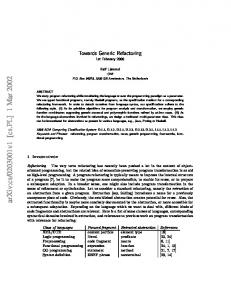
Consider the class diagram of Figure 2, which illustrates an application that has seven classes C1 , C2 , C3 , C4 , C5 , C6 , C7 , and eight methods m1 , m2 , m3 , m4 , m5 , m6 , m7 , m8 , implemented as shown in the classes. In order to apply the algorithm in Section 5.1, we must first identify the classes that are candidates for reuse in future applications: C1 , C2 , C4 and C6 as general, and C3 , C5 and C7 as specific, thereby setting the vector G = (0, 0, 1, 0, 1, 0, 1)T , which is Step 1 of the algorithm. Next, we determine the couplings among methods, and construct the zero-one matrix MΓm , such that
C1
-
m1 m2
¾
C2
C4
m3
4
J JJ J JJ J JJJ ^ J J ^ JJ J
m4 4
C3
C5 m5
C6
Á
m7 4
C7
m6
-
m8
Fig. 2. Initial Class Diagram.
it has a 1 as its (i, j) entry when i-th method is coupled to the j-th method, and a 0 if the methods are not coupled. From the class diagram in Figure 3, we construct the matrix MΓm shown below, which is Step 2 of the algorithm. Now, for simplicity, suppose all classes are related to one another, which leads to Γm = {C1 , C2 , C3 , C4 , C5 , C6 , C7 } × {C1 , C2 , C3 , C4 , C5 , C6 , C7 }, which is Step 3 of the algorithm. Then, using the reusability level for each class G, the coupling among the methods MΓm , and the relations among the classes ΓR , we calculate the matrix T = [tij ] shown below that represents the coupling types among the methods, which is Step 4 of the algorithm. Finally, from the matrix T = [tij ], we can identify the undesirable couplings {(m3 , m5 ), (m4 , m6 ), (m4 , m8 )}, which have values of 3, 3, and 3, in the matrix, and is the first use of Step 5 of the algorithm. Given all of these characteristics and assumptions, we can attempt
MΓm
0 0 0 0 = 0 0 0 0
0 0 0 1 0 0 0 0
1 0 0 0 0 0 0 0
0 0 0 0 0 0 0 0
0 0 1 0 0 0 0 0
0 0 0 1 0 0 0 0
0 0 0 0 1 0 0 0
0 0010 0 0 0 0 0 0 0 0 0 0 0 1 0 0 1 T = 0 0 0 0 0 0 0 0 0 0 0 0000 0 0000
0 0 3 0 0 0 0 0
0 0 0 3 0 0 0 0
0 0 0 0 5 0 0 0
0 0 0 3 0 0 0 0
to improve the reusability of the application via the refactoring operations presented in Steps 6, 7, and 8 of the algorithm in Section 5.1. – Consider the coupling (m3 , m5 ). Move the source method down the inhere M = {m4 } and C e M = {m3 }. Calculate Te, and itance hierarchy, so that C 2 3 then evaluate the reusability improvement factor, obtaining ∆ρ = 0. Since
this operation does not improve the reusability of the application, restore C2M = {m3 , m4 } and C3M = ∅. – Consider the coupling (m4 , m6 ). Move the source method down the inhere M = {m3 } and C e M = {m4 }. Calculate Te, and itance hierarchy, so that C 2 3 then evaluate the reusability improvement factor, obtaining ∆ρ = +1. Since e M , and C M = C e M , and identify a new ∆ρ is positive, set T = Te, C2M = C 2 3 3 coupling to continue refactoring. – Consider the coupling (m5 , m7 ). Move the source method up the inheritance e M = {m5 } and C e M = {m6 }. Calculate Te, and then hierarchy, so that C 4 5 evaluate the reusability improvement factor, obtaining ∆ρ = +2. Given the positive impact of the refactoring operation on reuse, we set T = Te, C4M = e M , and C M = C eM . C 4 5 5 Figure 3 illustrates the changes in the class diagram as a result of the refactoring operations, where method m4 has moved from C2 to C3 , and method m5 has moved from C5 to C4 . This has yielded a better overall software structure from a reusability perspective.
C1
C2
-
m1 m2
m3 4
C4
-
@ I @
@
m5 4
C6
-
m7 4
C5 C3
@
@
m4
© * ©©
C7
m6
-
m8
Fig. 3. Revised Class Diagram After Refactoring.
6
Related Research
There are several proposals to use formal methods in software reuse. In [8], a mathematical model based on discrete mathematics is discussed, that captures aspects of software reuse such as the representation of software components via formal specifications, the representation of user queries, the organization of software repositories, the definition of retrieval procedures, and the definition of a framework for the process of modifying software components to satisfy user queries. This effort shares our philosophy of attempting to formalize software specifications to allow software reuse, but differs since its focus is the introduction
of operators that reflect semantic distance between relational specifications and our focus is on the introduction of reusability metrics intended to be iteratively applied throughout the software process. In [5], a framework and algorithms for the maintenance problem that arises when reusing software components is presented, that addresses a way to prevent software-components-reuse defects such as logic subsumptions, redundancies, inconsistencies, and conflicts. Their solution to the reusability problem uses properties of inheritance relation such as in copyable and out copyable, as well as client-server fan in copyable and fan out copyable. Our approach shares their model of object structures as directed graphs where edges are associations and nodes are classes. An analytical and empirical evaluation of several published reuse metrics is presented in [2], which introduces properties that should hold in any measure of time, money, and quality benefit, as a result of software reuse. Several software reuse metrics are assessed using these properties, and evaluated empirically. This effort is of interest to our own work, since in the long-term, we are interested in comparing and contrasting our metric with other metrics that have been developed. In [9], a formal object-oriented meta-model is used for defining two measures of structural quality such as coupling and cohesion. In [19], a solution to the problem of measuring potential coupling between an application and its environment is proposed. Both of these efforts are relevant to our own work, since they focus on coupling, which is a key facet of our reuse framework, which drives both the metric calculation (see Section 3) and the reuse improvement via refactoring (see Sections 4 and 5.1).
7
Conclusions and Future Work
In this paper, we have extended the reusability framework for object-oriented design originally proposed in [12–15], through a formalization of those model concepts and the introduction of a methodology and associated processing for a refactoring algorithm that improves reuse. In our research, we identified a set of properties of the framework (see Section 3 again), formalized the representation of the characteristics proposed in [15] (see Sections 2 and 3 again), introduced the reusability improvement factor (see Section 4 again), and outlined an algorithm to improve the reusability which was demonstrated in an example application (see Section 5 again). Overall, we believe that we have taken a significant first step in establishing a formal framework for refactoring that can be the basis of continued research and development efforts. Thus, the work herein is an important part of ongoing research on reusable components (http://www.engr.uconn.edu/˜steve/DRE/dre.html). This site contains all of our research publications on reusable components, as well as the current prototype Design Reusability Evaluation (DRE) tool, which supports the original reuse model and framework [12–15]. We have a number of ongoing areas of investigation:
– We are exploring the transition weightings between coupling types (see Figure 1), to evaluate the impact on refactoring if different values are utilized (e.g., +2, -2, etc.), if diagonals are used, or if jumps across multiple levels of generality are allowed. Also, these weights may be definable, to some degree, by the software engineer who conducts reusability assessment and refactoring. Further, the current algorithm searches only in one step. Multiple steps that involve searching down bad paths (-1) for potential gain using hueristics may be possible. – We continue to extend, refine, and reformulate the reusability model. We are also exploring formal proofs for the properties upon which the reuse framework was built, and a theoretical verification that the refactoring algorithm actually improves the reuse potential. This will include issues such as inheritance vs. composition in the refactoring process and considering the impact on maintainability. – From a practical perspective, we have begun the process of integrating the model, metric, and refactoring algorithm into our ongoing DRE prototype. This will allow us to easily collect empirical evidence on the utility and operation of the refactoring algorithm. – While we believe that our reusability framework is applicable to large scale projects, a more realistic example which appeared in our prior work [12–14] would not fit into the space limitations of the paper. We continue to test our approach on other applications in order to gather empirical evidence on the utility of our algorithm vs. a human expert. Finally, note that we have also developed a genetic algorithm that, when given a set of classes and their couplings, determines a near-optimal general/specific marking for the classes, where the software engineer can specify the distribution of general/specific classes as an input to the genetic algorithm. We are investigating using this genetic algorithm as a prelude to mark classes before applying the algorithm given in Section 5.1. Acknowledgements The work of S. Demurjian has been supported, in part, by a contract from the Electric Boat Corporation, Groton, CT. We also wish to thank M. Price for her insightful comments and suggestions.
References 1. Software reuse executive premier. Technical report, DOD Software Reuse Initiative Program Management Office, 1996. 2. P. Devanbu, S. Karstu, W. Melo, and W. Thomas. Analytical and empirical evaluation of software reuse metrics. In Proceedings of 18th International Conference on Software Engineering, pages 189–199, March 1996. 3. M. Fowler. Refactoring, Improving the Design of Existing Code. Addison-Wesley, February 2001.
4. P. A. Hall. Architecture-driven component reuse. Information and Software Technology, 41(14):963–968, November 1999. 5. Y.-F. Hwang and D. C. Rine. Verifying the reusability of software component specifications: Framework and algorithms. Information Sciences, 112(1-4):169– 197, December 1998. 6. M. McIlroy. Mass produced software components. In Proceedings of the NATO Software Engineering Conference, Germany, October 1968. 7. J. Meekel, T. Horton, R. France, C. Mellone, and S. Dalvi. From domain models to architecture frameworks. In Proceedings of the 1997 Sympsium on Software Reusability, Boston, MA, May 1997. 8. R. Mili, J. Desharnais, M. Frappier, and A. Mili. Semantic distance between specifications. Theoretical Computer Science, 247(1-2):257–276, September 2000. 9. S. Moser and V. B. Misic. Measuring class coupling and cohesion: A formal method approach. In Proceedings of APSEC’97 and ICSC’97, pages 31–40, December 1997. 10. J. S. Poulin. Measuring Software Reuse: Principles, Practices and Economic Models. Addison-Wesley, November 1996. 11. P. E. Presson et al. Software interoperability and reusability. RADC-TR-83, 1, July 1983. 12. M. W. Price. Object-Oriented Design Methodology to Facilicate Reuse. PhD thesis, University of Connecticut, 1998. 13. M. W. Price and S. A. Demurjian. Analyzing and measuring reusability in objectoriented designs. In Proceedings of OOPSLA’97, pages 22–33, Atlanta, October 1997. 14. M. W. Price, S. A. Demurjian, and D. M. Needham. Reusability measurement framework and tool for ada95. In Proceedings of 1997 TriAda Conference, St. Louis, November 1997. 15. M. W. Price, D. M. Needham, and S. A. Demurjian. Producing reusable objectoriented components: A domain-and-organization-specific perspective. In Proceedings of 2001 Sympsium on Software Reusability, Toronto, Canada, May 2001. 16. L. Reyes and D. Carver. Predicting object reuse using metrics. In Proceedings of SEKE’98 Tenth International Conference on Software Engineering and Knowledge Engineering, pages 156–159, San Francisco, June 1998. 17. D. C. Rine and N. Nada. Three empirical studies of a software reuse reference model. Software - Practice and Experience, 30(6):685–722, May 2000. 18. K. H. Rosen. Discrete Mathematics and Its Applications. WCB McGraw-Will, fourth edition, 1999. 19. S. Rotenstreich. Toward measuring potential coupling. Software Engineering Journal, 4, March 1994. 20. M. Sarshar. Reuse measurement and assessment. In Proceedings of the International Workshop on Systematic Reuse, pages 52–63, Germany, January 1996. 21. A. Schmietendorf, R. Dumke, and E. Foltin. Metrics based asset assessment. Software Engineering Notes, 25(4):51–55, July 2000. 22. G. Succi, S. Doublait, C. Uhrik, and F. Baruchelli. Reuse and reusability metrics in an object oriented paradigm. In International Journal of Applied Software Technology, volume 1, pages 191–202, Canada, 1995. International Academic Publishing. 23. M. Tsagias and B. Kitchenham. An evaluation of the business object approach to software development. The Journal of Systems and Software, 52(2-3):149–156, June 2000.