Towards the Next Generation Network: The Softswitch Solution KARL-JOHAN GRINNEMO and ANNA BRUNSTROM
Department of Computer Science KARLSTAD UNIVERSITY Karlstad, Sweden 2006
Towards the Next Generation Network: The Softswitch Solution KARL-JOHAN GRINNEMO & ANNA BRUNSTROM Technical Report no. 2006:6 Department of Computer Science Karlstad University SE–651 88 Karlstad, Sweden Phone: +46 (0)54–700 1000
Contact information: Karl-Johan Grinnemo Telecom & Media TietoEnator AB Box 1038 SE–651 15 Karlstad, Sweden Phone: +46 (0)54–29 41 49 Fax: +46 (0)54–29 40 01 Email:
[email protected]
Printed in Sweden Karlstads Universitetstryckeri Karlstad, Sweden 2006
Towards the Next Generation Network: The Softswitch Solution KARL-JOHAN GRINNEMO & ANNA BRUNSTROM Department of Computer Science, Karlstad University
Abstract Over the course of the last fifteen years, the telecommunication market has undergone dramatic changes. In the beginning of the nineties, the market essentially comprised a number of national monopolies. Today, yesterday’s monopolies are under siege, and the incumbent operators face strong competition from newly established operators. Furthermore, in recent years broadband-based VoIP providers have entered the telecommunication market as worthy contenders to traditional operators. To be able to survive and thrive in this new, much more competitive, market, traditional wireless and wireline operators have to reduce their capital and operational expenditures. They also need to provide new revenue-generating applications and services. To this end, a large number of traditional operators has replaced, or seriously consider to replace, their legacy circuit-switched fixed and cellular core networks with IP. As a first step in the migration from circuit-switched technologies to IP, the softswitch solution has evolved. This report provides a comprehensive treatment of the softswitch solution from a technical viewpoint. Additionally, the report concludes with a brief discussion of the migration steps following the softswitch solution. In particular, an overview of the 3GPP IP Multimedia Subsystem (IMS) is given. Keywords: Next Generation Networks, softswitch, signaling, SS7, Parlay, JAIN, H.323, SIP, MEGACO, H.248, SIGTRAN, IMS
i
Acknowledgements This report has benefited from review by a number of people. A great many thanks goes to Dr. Reiner Ludwig (Senior Specialist, Ericsson Research, Aachen, Germany) and Mr. Rickard Persson (TietoEnator, Karlstad, Sweden) who provided technical reviews of the manuscript. Finally, I would like to thank the many people at TietoEnator who assisted me during the writing of this report.
iii
Contents 1
Introduction
1
2
Signaling in Today’s Telecommunication Networks 2.1 Taxonomy of Signaling . . . . . . . . . . . . . 2.2 SS7 Network Architecture . . . . . . . . . . . 2.3 The SS7 Protocol Stack . . . . . . . . . . . . . 2.4 SS7 in PSTN . . . . . . . . . . . . . . . . . . 2.5 SS7 in PLMN . . . . . . . . . . . . . . . . . . 2.6 Intelligent Networks . . . . . . . . . . . . . .
. . . . . .
. . . . . .
. . . . . .
. . . . . .
. . . . . .
. . . . . .
. . . . . .
. . . . . .
. . . . . .
. . . . . .
. . . . . .
. . . . . .
. . . . . .
3 3 6 7 13 15 20
3
The Softswitch Architecture
23
4
Applications and Services 4.1 Application Programming Languages . . . . . . . . . . . . . . . . . . 4.2 API Frameworks . . . . . . . . . . . . . . . . . . . . . . . . . . . . .
29 30 37
5
Call Control Signaling 5.1 H.323 . . . . . . . . . . . . . . . . . . . . . . . . . . . . . . . . . . . 5.2 SIP . . . . . . . . . . . . . . . . . . . . . . . . . . . . . . . . . . . . .
48 48 54
6
Bearer Signaling
61
7
Interworking with Legacy Circuit-Switched Networks 7.1 SCTP . . . . . . . . . . . . . . . . . . . . . . . . 7.2 Adaptation Component . . . . . . . . . . . . . . . 7.3 M2PA . . . . . . . . . . . . . . . . . . . . . . . . 7.4 M2UA . . . . . . . . . . . . . . . . . . . . . . . . 7.5 M3UA . . . . . . . . . . . . . . . . . . . . . . . . 7.6 SUA . . . . . . . . . . . . . . . . . . . . . . . . .
. . . . . .
. . . . . .
. . . . . .
. . . . . .
. . . . . .
. . . . . .
. . . . . .
. . . . . .
. . . . . .
. . . . . .
. . . . . .
66 67 71 73 75 76 78
8
Future Outlook
80
9
Summary
87
References
88
Abbreviations
94
v
1. Introduction
1
1
Introduction
Few industries have experienced a more revolutionary change than the one which has shaken the telecommunications industry in the last fifteen years. In the beginning of the nineties, the telecommunication market basically comprised a number of national monopolies or national incumbent operators. Today, incumbency in the telecom market has come under siege as a result of country-by-country telecom liberalization, deregulation, privatization, and competition. This process spread rapidly from the U.S. Telecommunications Act of 1996, through telecom reforms in each of 27 European countries during the second half of the 1990s, to India’s New Telecom Policy of 1999. Today, this process, and the industry re-alignment that it is causing, is far from over. The wireline landscape has changed dramatically over the past couple of years. A number of broadband access operators are competing for market shares, and consumers are increasingly aware that they can make low cost, or even free calls, to basically any destination in the world. This has positioned today’s wireline operators at a crossroad. On one hand, they need to decrease both capital and operational expenditures, on the other hand, they have a large installed base of legacy circuit-switched equipment that still generates the major part of their revenue. Also the wireless landscape is evolving. Although, the wireless industry is still a large and dynamic industry that continues to enjoy significant growth worldwide, it needs sustained revenue growth and improved cost efficiency to protect margins. The wireless industry is today a mature industry that has been globally available for quite some time. Growth of subscribers, traffic, and, most importantly, revenues, is by no means automatic. Entry costs for new users and tariffs must be continuously reduced to increase subscriber numbers and call minutes. Per unit pricing for as lucrative services as voice and Short Message Service (SMS) is eroding sharply in most markets. Thus, there is a strong belief in the wireless industry that new services are needed to drive revenue growth. Further, due to the ever increasing popularity of Internet and Internet-based multimedia services, it is considered vital that future wireless networks will seamlessly interwork with IP. To address the challenges facing today’s wireline and wireless industry, the so-called softswitch solution or architecture has evolved. The softswitch architecture provides a smooth first migration step from current circuit-switched fixed and cellular core networks to an all-IP, multi-service telecommunication network. Section 3 introduces the softswitch architecture, and discusses the incentives for both established incumbent operators and new competitive operators to embrace this architecture. As will become evident in Section 3, one of the key drivers of introducing the softswitch architecture is the promise of new revenue-generating applications and services. To this end, Section 4 surveys the application/service creation environments of the softswitch architecture. At the heart of a telecommunication network is signaling: Call signaling is paramount to manage call sessions, and bearer signaling to manage the actual media streams. Sections 5 and 6 discuss call and bearer signaling respectively in the softswitch architecture. Next, since legacy wireless and wireline circuit-switched core networks will most likely live on for the next decade or so, Section 7 examines the Internet Engineering Task Force (IETF) SIGnaling TRANsport (SIGTRAN) framework architecture for transportation of Signaling System No. 7 (SS7) signaling over IP. The report concludes in Section 8 with
2
1. Introduction
an outlook of the migration steps following the softswitch architecture. In particular, an overview of the 3rd Generation Partnership Project (3GPP) IP Multimedia Subsystem (IMS) is given. For those readers who are less familiar with signaling in current fixed and cellular telecommunication networks, Section 2 provides a brief introduction and summary of SS7, the most widely used signaling system in both the Public Switched Telephone Network (PSTN) and the Public Land Mobile Network (PLMN). The section also gives brief overviews of the architectures of the current PSTN and PLMN networks, and describes how SS7 is integrated into these networks.
2. Signaling in Today’s Telecommunication Networks
LE
1
2
3
4
5
6
7
8
9
8
#
*
3
LE Core Network
z 1
2
3
4
5
6
7
8
9
8
#
*
Access Signaling
Network Signaling
Access Signaling
LE = Local Exchange
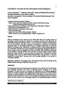
Figure 1: Access and network signaling in a telecommunication network.
2
Signaling in Today’s Telecommunication Networks
The term ’signaling’ is used in many contexts. In technical systems it commonly refers to control of procedures. Examples of technical systems which include some kind of signaling are network control systems, railway traffic systems, air traffic systems, process control systems, and, of course, telecom systems. In a telephony context, signaling means the distribution of information and instructions from one telephone node to one or several others to provide for calls, and for network management. The telecommunication sector of the International Telecommunication Union (ITU-T) defines signaling as “the exchange of information (other than by speech) specifically concerned with the establishment, release and other control of calls, and network management, in automatic telecommunications operation” [57]. The main purpose of using signaling in telecom networks, where different telephone nodes must cooperate and communicate with each other, is to enable transfer of control information between nodes in connection with: • traffic control procedures such as setup, supervision, and teardown of calls and services; • database communication, e.g., database queries concerning specific services, roaming in cellular networks etc.; and • network management procedures, e.g., blocking or de-blocking of signaling links.
2.1 Taxonomy of Signaling Traditionally, signaling in a telecommunication network is divided into two types: subscriber or access signaling and trunk or network signaling. As Figure 1 illustrates, access signaling denotes the signaling that takes place between a subscriber terminal, e.g., a phone, and a local exchange, while network signaling denotes the signaling that occurs between exchanges. In this report, only network signaling is considered. Network signaling has further been divided into Channel Associated Signaling (CAS) and Common Channel Signaling (CCS). The key feature that distinguishes CAS from CCS is the deterministic relationship between the voice circuits and the call-control signals controlling the voice circuits in CAS. Particularly, in CAS, a dedicated, fixed
4
2. Signaling in Today’s Telecommunication Networks
Associated Mode
Exchange
Exchange
Exchange
Quasi-Associated Mode
Non-Associated Mode
Exchange
Signaling Transfer Point
Exchange
Signaling Transfer Point
Exchange
Signaling Transfer Point
Exchange
Signaling Transfer Point
Bearer Traffic Signaling Traffic
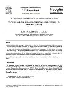
Figure 2: Common channel signaling modes.
signaling capacity is set aside for each and every voice circuit in a pre-determined way, while, in CCS, the signaling capacity is provided in a common pool for several voice circuits, and with the capacity being used as and when necessary. In fact, a signaling circuit in CCS is typically able to carry signaling information for thousands of voice circuits. Network signaling was previously implemented using CAS techniques and systems. However, for the past two decades, it has been replaced with CCS systems. CCS systems are packet based, i.e., the signaling information is transferred as messages. Thus, there is no rigid tie between the signaling and the adhering voice circuits, which makes two different types of CCS signaling feasible: circuit-related signaling and non-circuit related signaling. Circuit-related signaling refers to the original usage of signaling, which was to establish, supervise, and release voice circuits. In contrast, noncircuit related signaling refers to signaling that is not related to the management of voice circuits. Specifically, with the advent of cellular networks and Intelligent Network (IN) services, there was a need for non-circuit related signaling in connection with database accesses. Apart from some remnants of Signaling System No. 6 (SS6), Signaling System No. 7 (SS7) is the CCS system of use in today’s telecommunication networks. Since there is no inherent relationship between voice circuits and signaling in a CCS system, three types of, so-called, signaling modes have been defined: associated, non-
2. Signaling in Today’s Telecommunication Networks
5
STP
STP
STP
STP
SCP
SSP
SSP
Bearer Traffic Signaling Traffic
SCP = Service Control Point SSP = Service Switching Point STP = Signaling Transfer Point
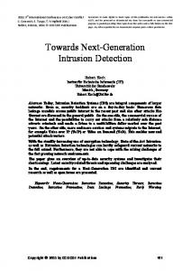
Figure 3: A logical view of the SS7 network architecture.
associated, and quasi-associated. The signaling mode of a CCS system is determined on the basis of how circuit-related signaling is routed through the system. In associated mode, the signaling and the corresponding bearer traffic take the same route through the telecommunication network. Contrary to this, in non-associated mode the signaling and bearer traffic are routed separately. Furthermore, the route taken by the signaling traffic for a specific bearer traffic is not fixed. That is, the signaling has many possible routes through the network for a given call or transaction. The quasi-associated mode of signaling could be seen as a limited case of the non-associated mode where the route taken by the signaling traffic for a specific bearer traffic is predetermined and, at a given point in time, fixed. Figure 2 shows the three different types of CCS signaling modes. SS7 is only specified for use in the associated and quasi-associated modes, and does not support non-associated signaling. Associated signaling is the common means of implementation outside of U.S., e.g., in Europe. However, in U.S., quasi-associated signaling is frequently used. Since the way associated signaling is implemented differs greatly between different nations, and, since quasi-associated signaling gives a cleaner interface between signaling and bearer traffic, the signaling examples in the text that follows assume quasi-associated signaling.
6
2. Signaling in Today’s Telecommunication Networks
STP
STP Route
SCP
Route STP
STP
Linkset
Linkset Routeset
SSP
SSP
Bearer Traffic Signaling Traffic
SCP = Service Control Point SSP = Service Switching Point STP = Signaling Transfer Point
Figure 4: Link, linkset, route, and routeset.
2.2 SS7 Network Architecture As already mentioned, SS7 is the prevailing network signaling system in today’s telecommunication networks, in both the PSTN and the PLMN networks. Logically, as illustrated in Figure 3, SS7 constitutes a separate network within a telecommunication network, however, physically, SS7 establishes a framework between telecom exchanges and dedicated signaling nodes by which signaling information is exchanged via dedicated signaling circuits. These circuits are known as signaling data links or simply links. Each signaling node and SS7-aware exchange acts as a Signaling Point (SP), and communicates with other SPs via dedicated links. Links connect SPs to their neighbors and form communication paths or routes between them. Within an SS7 network, all SPs are identified by a unique address. This address is called a point code. All SS7 messages have a point of origin and a point of destination, and hence are assigned an Originating Point Code (OPC) and a Destination Point Code (DPC). Routing in SS7 is in part done on the basis of the DPC of a message. To provide more bandwidth and/or redundancy, links are usually organized into groups known as linksets. A linkset is a collection of links that share the same destination and are for the most part established directly between SPs. When links are collected in linksets, the total load of traffic is typically shared between active links. There can be up to 16 links in a linkset, and a single SP may support a number of linksets in between itself and other SPs. When one SP is reachable from another SP, there is said to be a route between the
2. Signaling in Today’s Telecommunication Networks
7
two. In other words, a route is the path that exists between any two SPs. The route may comprise a single linkset or multiple linksets; the term simply refers to the existence of a network path between two SPs. Where alternative routes exist between two SPs, they together constitute a routeset. Figure 4 exemplifies the concepts of link, linkset, route, and routeset. As illustrated in Figure 3, an SS7 network includes a number of different types of SPs. In fact, there can be three different types of SPs in an SS7 network: • Service Switching Points (SSPs). SSPs are SS7-aware exchanges that originate, terminate, and, if integrated STPs (see below), forward calls. An SSP sends signaling messages to other SSPs to setup, manage, and release voice circuits required to complete a call. An SSP may also send queries to Service Control Points (SCPs), e.g., to determine how to route a call or in connection with an IN service (see Section 2.6). • Signaling Transfer Points (STPs). STPs are packet switches that route traffic between SPs. There are two types of STPs: standalone STPs and integrated STPs. A standalone STP means that the STP functionality is allocated to an SS7 node whose only task is to operate as an STP. In contrast, an integrated STP is an SSP with STP functionality. • Service Control Points (SCPs). SCPs are centralized network databases that underpin IN services and subscriber mobility in cellular networks. The SCP accepts queries from an SSP and returns the requested information. For example, an SSP calls an SCP to determine the routing of a toll-free call. Additionally, it should be mentioned that an SSP or SCP that either originates or terminates signaling traffic is also called a Signaling End Point (SEP).
2.3 The SS7 Protocol Stack As outlined in Figure 5, the protocol stack of SS7 basically comprises two main functional parts: a Network Service Part (NSP) and a User Part (UP). The NSP is primarily concerned with the transportation of signaling messages between application protocols or UP protocols, while the UP protocols themselves are responsible for the actual processing of signaling messages. The NSP is common to all application areas, e.g., the PSTN, the PLMN, and the IN services, while the protocols of the UP to a large extent depend on the particular application area. The NSP comprises two functional parts: the Message Transfer Part (MTP) and the Signaling Connection Control Part (SCCP). In Figure 6, a more detailed view of the SS7 protocol stack is given. As follows, the MTP consists of three parts: • MTP Level 1 (MTP-L1). MTP-L1 refers to the signaling data link and defines the physical, electrical, and functional characteristics of the link. It also defines the means to connect a signaling data link to exchanges. In the PSTN and PLMN core networks, trunks carry voice and signaling traffic between exchanges. While analog trunks still exist, the majority of trunks in
8
2. Signaling in Today’s Telecommunication Networks
Exchange
Exchange
Message handling UP
UP
SCCP
SCCP Message transfer
NSP MTP
MTP
Message transmission
MTP = Message Transfer Part NSP = Network Service Part SCCP = Signaling Connection Control Part UP = User Part
Figure 5: The main structure of the SS7 protocol stack.
Exchange
Exchange
TCAP
TCAP ISUP
SCCP
ISUP SCCP
MTP-L3
MTP-L3
MTP-L2
MTP-L2
MTP-L1
MTP-L1
ISDN = Integrated Services Digital Network ISUP = ISDN User Part MTP = Message Transfer Part MTP-L1 = MTP Level 1 MTP-L2 = MTP Level 2 MTP-L3 = MTP Level 3 SCCP = Signaling Connection Control Part TCAP = Transaction Capabilities Application Part
Figure 6: A more detailed view of the SS7 protocol stack.
2. Signaling in Today’s Telecommunication Networks
9
T1 Framing Format Signaling occupies the LSB in every sixth frame
Timeslot
Voice Circuit #1
Voice Circuit #2
Voice Circuit #3
Voice Circuit #24
24 Voice Circuits
E1 Framing Format Timeslot
Framing Slot
Voice Circuit #1
Voice Circuit #15
Signaling Slot
Voice Circuit #30
30 Voice Circuits
LSB = Least Significant Bit
Framing Bit
Signaling bit
Figure 7: The T1 and E1 framing formats. use today are digital. Digital trunks mostly employ Time Division Multiplexing (TDM), and are either of type T1 or E1; U.S. uses T1 while Europe uses E1. On a T1/E1 trunk, voice and signaling circuits are multiplexed into digital bit streams. Figure 7 shows the T1/E1 framing formats. As follows, each voice circuit occupies one timeslot in a T1/E1 frame, and there are 24 multiplexed voice circuits in a T1 frame, and 30 voice circuits in an E1 frame. A signaling link is implemented differently in T1 and E1. In E1, the signaling link is implemented by using one of the voice circuits in each E1 frame for signaling. However, in T1 no single timeslot is dedicated for signaling, instead a signaling link is implemented as one bit in every timeslot of every sixth frame. The transmission service provided by T1/E1 trunks is typically expressed according to the so-called Digital Signal (DS) service hierarchy. The basic unit of transmission on a T1 trunk is 56 kbps and is designated DS-0A, and the basic transmission unit on an E1 trunk is 64 kbps and is designated DS-0. A T1 trunk has a capacity of 24 DS-0As, and an E1 trunk a capacity of 30 DS-0s. • MTP Level 2 (MTP-L2). MTP-L2 together with MTP-L1 provides for reliable signaling on a single signaling link in between two adjacent SPs. Specifically, MTP-L2 incorporates such capabilities as message delimitation, link error detection, link error correction, link error monitoring, and link flow control. • MTP Level 3 (MTP-L3). Basically, MTP-L3 extends the functionality of MTPL2 to signaling routes. The MTP-L3 functions can be divided into two basic categories: Signaling Message Handling (SMH) and Signaling Network Manage-
10
2. Signaling in Today’s Telecommunication Networks
NI
SIF
User Data
Spare
SI
SIO
Routing Label
SLS
OPC
DPC
DPC = Destination Point Code MTP-L2 = Message Transfer Part Level 2 NI = Network Indicatior OPC = Originating Point Code SI = Service Indicator SIF = Signaling Information Field SIO = Service Information Octet SLS = Signaling Link Selector
Figure 8: Routing label and other fields used by MTP-L3 for routing. ment (SNM). The SMH functionality is done on the basis of the routing label and the Service Information Octet (SIO) fields of an SS7 message (see Figure 8), and can further be divided into message discrimination, message distribution, and message routing. Message discrimination is the task of determining whether an incoming signaling message is destined to the SP currently processing the message. It makes this determination using the DPC and Network Indicator (NI) fields of the message. When the discrimination function has determined that a message is destined for the current SP, it performs the message distribution function by examining the Service Indicator (SI) field. The SI field indicates which MTP-L3 user (i.e., either SCCP or a UP protocol) the message should be forwarded to for further processing. Routing takes place when the current SP has determined that a received message is to be sent to another SP. The selection of an outgoing link is done based on the values of the DPC and the Signaling Link Selector (SLS) fields. Each SP that provides STP functionality has a routing table that is continuously updated with link status information. By mapping the DPC and SLS values of the received message against this table, a suitable outgoing link is obtained. The purpose of the SNM functionality is to provide for signaling link management, signaling route management, and signaling traffic management. Signaling link management entails the management of locally attached signaling links. In particular, SNM includes link management capabilities for link activation, deactivation, restoration, and linkset activation. The signaling route management
2. Signaling in Today’s Telecommunication Networks
11
includes the functions needed to distribute information to adjacent SPs about the status of signaling routes. Finally, the signaling traffic management concerns the rerouting of signaling traffic from failed routes. It also concerns route-level congestion control. MTP only supports circuit-related signaling, and SCCP was added to SS7 primarily to provide for non-circuit related signaling. In particular, it appeared in the second version of SS7 in 1984 to provide for non-circuit related signaling in connection with IN and cellular networks. The second major contribution of SCCP is a new routing mechanism, Global Title Routing (GTR), that complements MTP-L3 with incremental routing. A Global Title (GT) is an address which in itself does not contain the information necessary to perform routing in an SS7 network. There are numerous examples of GTs: in fixed networks, toll-free (e.g., 020-numbers) and premium-rate numbers are examples of GTs, and in cellular networks, the Mobile Subscriber Integrated Services Digital Network (MSISDN) and International Mobile Subscriber Identity (IMSI) are examples of GTs. GTR frees originating SPs from the burden of having to know every potential destination to which they might have to route a message. When GTR is used, an SP, e.g., an SSP, does not have to determine the final destination of a message. Instead, it might query an STP that does GT translation, a so-called SCCP Relay Point (SRP), about the next SP along the route towards the destination. The next SP is either the final destination or yet another SRP. If the next SP is an SRP, a new GTT (Global Title Translation) is made when the message arrives at this SP. The routing continues in this incremental way until the final SP is reached. As mentioned earlier, in contrast to the NSP, the UP is to a large extent application dependent. However, two UP protocols stand out as being more important than others: the Integrated Services Digital Network (ISDN) UP protocol (ISUP) and the Transaction Capabilities Application Part (TCAP). ISUP is the UP protocol of the SS7 stack primary responsible for all circuit-related signaling. It conveys the signaling necessary to establish and maintain call connections. Each exchange gets the call signaling information from the previous exchange along the voice circuit as the connection is being established. Thus, ISUP messages are forwarded through the SS7 network from SSP to SSP parallel to the voice circuit being established. To illustrate the functionality of ISUP, Figure 9 shows the basic steps of a call setup between a calling party, A, and a called party, B, in the PSTN. The steps are as follows: (1) The call setup begins when A initiates a call using an access signaling protocol, e.g., Q.931 or V5.2. In this particular example, A employs Q.931 and sends a Q.931 SETUP message to SSP-1. (2) When SSP-1 receives the SETUP message, it sends an ISUP Initial Address Message (IAM) to STP-1. The IAM contains the information that is necessary to establish a call between A and B, such as the phone number of B. (3) On receiving the IAM from SSP-1, STP-1 sets up a voice channel between SSP-1 and SSP-2. Furthermore, STP-1 forwards the IAM to SSP-2.
12
2. Signaling in Today’s Telecommunication Networks
A (calling party)
SSP-1
STP-1
SSP-2
B (called party)
SETUP IAM IAM SETUP ALERTING ACM ACM
CONNECT CONNECT ACK
ALERTING ANM ANM CONNECT CONNECT ACK Conversation
ACM = Address Complete Message ANM = ANswer Message IAM = Initial Address Message SSP = Service Switching Point STP = Signaling Transfer Point
Figure 9: The ISUP call-setup procedure in the PSTN. (4) SSP-2, on receiving the IAM from STP-1, notifies the called party, B, using access signaling. In this example, a Q.931 SETUP message is sent to B. (5) B optionally responds with a Q.931 ALERTING message, which is passed backwards through the network as an ISUP Address Complete Message (ACM). When SSP-1 receives the ACM, a Q.931 ALERTING message is sent to A. At this point, A hears a ringback tone. (6) At the time B answers the call, a Q.931 CONNECT message is sent back to SSP2. SSP-2 responds with a Q.931 CONNECT ACK. It also sends an ISUP ANswer Message (ANM) backwards to SSP-1, which, when receiving the ANM issues a Q.931 CONNECT message to A. A responds to this message with a Q.931 CONNECT ACK. (7) The call setup is complete, and the conversation can commence. The second major UP protocol is TCAP. TCAP was primarily introduced in SS7 to provide a generic transaction protocol for IN services and cellular networks. For example, an SSP uses TCAP to query an SCP when it has to determine the route for a toll-free or premium-rate call. TCAP is also used in connection with a mobile user roaming into a new Mobile Switching Center (MSC)/Visitor Location Register (VLR) service area.
2. Signaling in Today’s Telecommunication Networks
13
TCAP is primarily designed to be used for querying and retrieval of information from SCPs. Logically, the TCAP protocol comprises two subparts: a component subpart and a transaction subpart. Operations and their results are transmitted in between an SP and an SCP as components. There are four types of components: • Invoke. The Invoke component is used to send an operation to an SCP. • Return Result. The result from an Invoke component is returned in the form of an Return Result component. • Return Error. If an operation fails, a Return Error component is returned. • Reject. The Reject component reports the receipt and rejection of an incorrect component such as a badly formed Invoke. The component subpart is responsible for accepting components from a TCAP user and delivering those components, in order, to the recipient TCAP user. To be able to do so, the component subpart employs the transaction subpart. The transaction subpart packetizes components into messages, and sends the messages in the form of transactions to the recipient TCAP user. There are five types of transaction-subpart messages: Begin, Continue, End, Abort, and Unidirectional. A Begin message starts a transaction; one or several Continue messages are used following a Begin message; and the End message terminates a successful transaction. The Abort message is used to terminate an unsuccessful transaction, i.e., a transaction in which an abnormal situation has occurred. Unidirectional messages are used in transactions that only contains requests and no replies.
2.4 SS7 in PSTN Typically, the exchanges of the PSTN are organized in a hierarchy as depicted in Figure 10. Subscribers are attached to Local Exchanges (LEs). The LEs are interconnected locally, and are aggregated upwards toward Tandem Exchanges (TEs) or Regional Transit Exchanges (RTEs). The RTEs are, in turn, aggregated toward National Transit Exchanges (NTE), and, at the topmost level, there are International Transit Exchanges (ITEs) which bind together different countries. At the time of the inception of SS7, i.e., in the beginning of the 1980s, the general structure of the PSTN was already in place and represented a substantial investment. To this end, SS7 was designed to integrate easily with the existing PSTN. In particular, the requirements of the PSTN have traditionally been met by organizing the SS7 network as a four-level hierarchy with SEPs, and regional, national, and international STPs supporting the signaling for the corresponding levels of PSTN exchanges. Figure 11 outlines this SS7 architecture, and also shows how the SPs map to different PSTN exchanges. In the majority of cases, the STPs are integrated with the corresponding transit exchanges, however, in some crowded areas, standalone STPs might be deployed. On the basis of the SS7 network hierarchy, one differentiate between six different types of signaling links (see Figure 12): • Access Link (A Link). An A link connects a SEP to an STP. Only messages originating from or destined to a SEP are transmitted on an A link.
14
2. Signaling in Today’s Telecommunication Networks
ITE
NTE
NTE
RTE
LE
RTE
LE
LE
RTE
LE
LE
LE
ITE = International Transit Exchange NTE = National Transit Exchange LE = Local Exchange RTE = Regional Transit Exchange
Figure 10: A generic PSTN architecture.
• Bridge Link (B Link). A B link connects STPs belonging to the same hierarchical level. Typically, quads of B links interconnect mated pairs of STPs in different regions. Since the hierarchical level of an STP can be rather ambiguous, B links are sometimes referred to as B/D links. • Cross Link (C Link). A C link connects STPs performing identical functions into a so-called mated pair. Mated STPs are used to enhance the reliability of the signaling network. A C link is only transporting signaling traffic when an STP has no other route available to an SP. • Diagonal Link (D Link). A D link connects STPs belonging to different hierarchical levels. Apart from this, D links are the same as B links. • Extended Link (E Link). An E link provides an alternate or backup link to an A link. E links are scarcely used in SS7 networks since the benefit of a marginally higher degree of reliability does not usually justify the added expense of an extra link. • Fully Associated Link (F Link). An F link provides a direct connection between two adjacent SEPs. As for E links, F links are rarely used.
2. Signaling in Today’s Telecommunication Networks
I -STP
I-STP
N-STP
N-STP
R-STP
R-STP
R-STP
R-STP
S-STP
S-STP
SEP
SEP
SEP SEP
Town Area West
15
SEP
SEP SEP
Metropolitan Area
SEP
SEP
Town Area East
I-STP = International STP N-STP = National STP R-STP = Regional STP SEP = Signaling End Point STP = Signaling Transfer Point S-STP = Standalone STP
Figure 11: Traditional SS7 signaling network architecture in the PSTN.
2.5 SS7 in PLMN Signaling in the PLMN is much more complex and demanding than in the PSTN. In addition to the signaling required in the PSTN, the PLMN needs signaling to cater for mobility management. In fact, in the PLMN the largest part of the SS7 signaling concerns the mobility management, and only a fraction of the signaling pertains to call control. The predominant PLMN system in use today is the Global System for Mobile communication (GSM). Figure 13 shows the general GSM architecture. As can be seen, the GSM architecture comprises three subsystems: the Base Station Subsystem (BSS), the Network and Switching Subsystem (NSS), and the Operation and Support Subsystem (OSS). The BSS is responsible for all radio-access signaling and is comprised of the Base Transceiver Station (BTS) and the Base Station Controller (BSC). The NSS is responsible for call processing and management of cellular users. The NSS includes the following logical network nodes: • Mobile Switching Center (MSC). The MSC is responsible for mobility management. It also acts as the interface between different operator’s cellular networks, the PSTN, and other external networks, e.g., the Internet. To keep the complexity of the GSM network down, typically only a few MSCs interface with external
16
2. Signaling in Today’s Telecommunication Networks
National Level N-STP
N-STP
D Link
N-STP
N-STP
Regional Level R-STP
SEP
E Link
R-STP
D Link
B Link
C Link
B Link R-STP
F Link
R-STP
A Link SEP
Town Area West N-STP = National STP R-STP = Regional STP SEP = Signaling End Point SSP = Service Switching Point STP = Signaling Transfer Point
Figure 12: SS7 signaling link types. networks. These MSCs are called Gateway MSCs (GMSCs). • Home Location Register (HLR). The HLR is a database or SCP used for storage and management of subscriptions. The HLR is considered the most important database as it stores permanent data about subscribers, including a subscriber’s service profile, location information, and activity status. When a person acquires a subscription from a cellular operator, he or she is registered in the HLR by the operator. • Visitor Location Register (VLR). The VLR is a database that contains temporary information about subscribers that is needed by the MSC in order to service visiting subscribers. The VLR is usually integrated with the MSC. When a cellular phone roams into a new MSC service area, the VLR connected to that MSC will request data about the subscription from the HLR of the phone. Later, if the phone makes a call, the VLR will have the information needed for call setup without having to contact the HLR. • Authentication Center (AuC). The AuC is a database that stores authentication and encryption parameters for subscribers to enable subscriber verification, and to provide confidentiality of calls.
2. Signaling in Today’s Telecommunication Networks
17
OMC BTS
OSS BSC
BTS
B HLR
BTS
AuC
MSC VLR
BTS
EIR
NSS BSC
BTS
GMSC MSC
A
BTS
PSTN PLMNs Internet etc.
BSS
AuC = Authentication Center BSC = Base Station Controller BSS = Base Station Subsystem BTS = Base Transceiver Station EIR = Equipment Identity Register GMSC = Gateway MSC HLR = Home Location Register MSC = Mobile Switching Center NSS = Network and Switching Subsystem OMC = Operation and Maintenance Center OSS = Operation and Support Subsystem PLMN = Public Land Mobile Network PSTN = Public Switched Telephone Network VLR = Visitor Location Register
Figure 13: The GSM architecture.
• Equipment Identity Register (EIR). The EIR is a database that holds all valid mobile equipment, e.g., cellular phones, in the GSM network. Thus, the EIR prevents calls from stolen or unauthorized cellular phones. The OSS consists of Operation and Maintenance Centers (OMCs) that are responsible for monitoring and controlling the cellular network. The OSS is typically proprietary and differs between vendors. Figure 14 shows a cross-section of the GSM architecture in Figure 13 along the line A-B. In particular, it shows the extension of SS7 signaling in the GSM architecture. As follows, SS7 signaling is used up to the BSC. Between the BSC and the BTS, as well
18
2. Signaling in Today’s Telecommunication Networks
BTS
BSC
MSC
HLR
BSSAP
LAPDm
LAPDm
LAPD
D-channel Signaling
LAPD
MAP
MAP
TCAP
TCAP
BSSAP
SCCP
SCCP
SCCP
SCCP
MTP
MTP
MTP
MTP
SS7 Signaling
BSSAP = Base Station System Application Part BSC = Base Station Controller BTS = Base Transceiver Station HLR = Home Location Register MAP = Mobile Application Part MSC = Mobile Switching Center LAPD = Link Access Procedure on D-channel LAPDm = LAPD modified MTP = Message Transfer Part SCCP = Signaling Connection Control Part TCAP = Transaction Capabilities Application Part
Figure 14: SS7 signaling in the GSM architecture.
as between the BTS and the cellular phone, a signaling system based on the Digital Subscriber Signaling System No. 1 (DSS1) is used. The SS7 signaling protocol used between the MSC and the BSC is the Base Station System Application Part (BSSAP). The BSSAP protocol transports mobility and connectivity management information to the MSC from the BSC. In the remaining parts of the GSM architecture, the prevailing SS7 protocol is the Mobile Application Part (MAP) protocol. MAP resides above TCAP. It is used to permit the network nodes of the NSS to communicate with each other to provide services such as roaming, text messaging (i.e., SMS), and subscriber authentication. Over the past several years, the Universal Mobile Telecommunications System (UMTS) has slowly began to take market shares from GSM. UMTS is actually not a new PLMN system, but an evolution of GSM. Figure 15, provides a schematic view of the UMTS architecture. The NSS and OSS parts of UMTS are almost the same as for GSM. Instead, the major differences are found in the access network. To accommodate the new principles for air-interface transmission (i.e., Wideband Code Division Multiple Access (WCDMA) instead of Time Division Multiple Access (TDMA) or Frequency Division Multiple Access (FDMA)), the GSM BSS is replaced with a new Radio Access
2. Signaling in Today’s Telecommunication Networks
19
OMC
Node B
OSS Node B
RNC
HLR
AuC
Node B MSC VLR Node B
EIR
NSS Node B
RNC GMSC MSC
Node B
PSTN PLMNs Internet etc.
RAN
AuC = Authentication Center EIR = Equipment Identity Register GMSC = Gateway MSC HLR = Home Location Register MSC = Mobile Switching Center NSS = Network and Switching Subsystem OMC = Operation and Maintenance Center OSS = Operation and Support Subsystem RAN = Radio Access Network RNC = Radio Network Controller VLR = Visitor Location Register
Figure 15: The principal UMTS architecture.
Network (RAN): the UMTS Terrestrial Radio Access Network (UTRAN). Two new logical network nodes are introduced in UTRAN: the Radio Network Controller (RNC) and Node B. The RNC is connected to one or several Node B nodes, each of which can serve one or several cells. The RNC performs essentially the same functions as the GSM BSC, and Node B is more or less an upgrade of the GSM BTS. From an SS7 signaling viewpoint, the major difference between GSM and UMTS is a new signaling protocol, the Radio Access Network Application Part (RANAP) that replaces the BSSAP protocol as the signaling protocol used between the MSC and the RNC.
20
2. Signaling in Today’s Telecommunication Networks
Query SSP
Response
SCP
SCP = Service Control Point SSP = Service Switching Point
Figure 16: A simple IN service.
2.6 Intelligent Networks The Intelligent Network (IN) is an architecture that redistributes a portion of the call processing that is traditionally performed by exchanges to other network nodes with the incentive to provide telecom operators with the means to develop and control applications and services more efficiently. Furthermore, IN makes customization of services to the needs of individual users significantly much easier. Examples of services realized by IN include: toll-free calls, universal access numbers, premium-rate calls, credit-card calls, and televoting. In its simplest form, an SSP that communicates with an SCP to retrieve information about how to process a phone call demonstrates an IN service (see Figure 16). The IN service can be triggered in various ways, but most often the service is triggered by the user dialing phone numbers that have a special meaning, e.g., toll-free phone numbers. When the service is triggered, the SSP issues a query to the SCP; the SCP runs the corresponding Service Logic Program (SLP) and returns with a response to the SSP, which continues processing the phone call. An IN network consists of several components that work collectively to deliver services. Figure 17 shows a fairly complete view of the IN network architecture. The SSP represents the traditional exchange, but enhanced to support IN processing. The SSP performs basic call processing and provides trigger and event detection points for IN processing. The SCP, Adjunct, and Intelligent Peripheral are all additional nodes that were added to support the IN architecture: • SCP. The SCP stores service data and executes service logic for incoming messages. The SCP acts on the information in a received message by invoking the appropriate SLP, and retrieving the necessary data for service processing. It then responds with instructions to the SSP about how to proceed with the call. The SCP can be specialized for a particular type of service, or it can implement several types of services. • Adjunct. The Adjunct performs similar functions to an SCP but, contrary to an SCP, an Adjunct is often co-located with the SSP. • Intelligent Peripheral. The Intelligent Peripheral provides specialized functions for call processing including voice announcements, voice recognition, and digit
2. Signaling in Today’s Telecommunication Networks
21
SCE
SCP
SCP
STP
STP Adjunct
SSP
SSP
Intelligent Peripheral
SCE = Service Creation Environment SCP = Service Control Point SSP = Service Switching Point STP = Signaling Transfer Point
Figure 17: The IN network architecture.
SSP
STP SCP
INAP
INAP
TCAP
TCAP
SCCP
SCCP
SCCP
SCCP
MTP
MTP
MTP
MTP
INAP = Intelligent Networking Application Part ISDN = Integrated Services Digital Network ISUP = ISDN User Part MTP = Message Transfer Part SCP = Service Control Point SCCP = Signaling Connection Control Part SSP = Service Switching Point STP = Signaling Transfer Point TCAP = Transaction Capabilities Application Part
Figure 18: IN in SS7.
22
2. Signaling in Today’s Telecommunication Networks
collection. • Service Creation Environment (SCE). The SCE enables operators, service providers, and third-party vendors to prototype, test, and deploy new applications and services. With respect to SS7, IN is implemented as UP protocols atop TCAP (see Figure 18). Throughout Europe, the Intelligent Networking Application Part (INAP) is the prevailing IN protocol. In brief, INAP is responsible for keeping track of the TCAP components exchanged between an SSP and an SCP. The INAP protocol ensures that the contents of the IN operations sent in TCAP components follow a predefined syntax as regards permitted parameters and their coding.
3. The Softswitch Architecture
23
Softswitch Solution Application & Services
Traditional Telecom Switch Application & Services
Call Control & Switching
Call Control & Switching
Transport
Transport
Figure 19: The principal idea behind the softswitch architecture.
3
The Softswitch Architecture
As mentioned in Section 1, both the wireline and wireless industry see the softswitch architecture as a key component in the next-generation telecommunication network. In fact, several operators and vendors see the advent of the softswitch architecture as pivotal for continued cost efficiency and revenue growth. The term ’softswitch’ was coined by one of the founders of the Softswitch Consortium, Ike Elliott, in the late nineties. Although frequently used, the term is quite elusive. In fact, to our knowledge, there exists no precise definition of the term. Still, there seems to be a fairly broad consensus on the principal components of the softswitch architecture and the salient functions of a softswitch. The principal idea behind the softswitch architecture is to separate the control and media functions of a traditional telecom switch. In particular, as illustrated in Figure 19, the softswitch architecture prescribes a separation and/or distribution of the application, call control, and media transport functions of legacy telecom switches. That is, the architecture decouples the underlying switching hardware from the control, service, and application functions. Figure 20 illustrates the distributed architecture that is generally agreed upon as the softswitch architecture. The architecture is bearer independent, and could be applied to both packet- and circuit-switched networks. However, given that the next-generation telecommunication networks are assumed to be packet switched, the softswitch architecture is almost exclusively applied to packet-switched networks. In fact, in the contexts used, it is often tacitly assumed that the underlying network is either IP-based or based on Asynchronous Transfer Mode (ATM). As follows from Figure 20, the principal components of the softswitch architecture are softswitch, Media Gateway (MG), Signaling Gateway (SG), and Feature/Application Server (AS). The softswitch constitutes the ’intelligence’ that coordinates all signaling
24
3. The Softswitch Architecture
Feature/Application Server
Signaling Gateway
Softswitch
Media Gateway
Figure 20: The softswitch architecture components.
such as call-control signaling, operations and management signaling, and bearer signaling. The name ’softswitch’ originates from the fact that the majority of signaling functionality in a softswitch resides in software as compared to hardware in traditional telecom switches. The primary functions typically found in a softswitch are depicted in Figure 21. The Call Agent Function (CA-F) administers the call-control signaling and provides the call-state machine for end points. Its primary role is to provide the call logic, and in so doing interact with CA-Fs in peer softswitches. It also acts as a proxy for the AS, and assists the AS in providing services and applications to the end user. The Media Gateway Controller Function (MGC-F) controls and monitors the MGs, i.e., is responsible for the bearer control. Specifically, it controls the creation, modification, and deletion of media streams. If needed, it also acts as a conduit for media parameter negotiation between other MGC-Fs and external networks. A softswitch is often responsible for routing of signaling messages between peer softswitches and non-softswitch networks such as PSTN and PLMN networks. In Figure 21, the Router Function (R-F) embodies the softswitch routing functionality. Other functions that are not shown in Figure 21 but still could be part of a softswitch include: Accounting Function (A-F), Border Gateway Function (BG-F), and various proxies, e.g., for the Wireless Application Protocol (WAP), Java APIs for Integrated Networks (JAIN), Parlay, and the Call Processing Language (CPL). The MG serves as a gateway between two separate networks, e.g., two packetswitched networks under different administrative control, or two networks employing different bearer technology such as IP to TDM, IP to ATM, or IP to 3G. Its primary role is to transform media from one transmission format to another. For example, an MG may terminate voice calls from a PSTN, compress and packetize voice data, and deliver compressed voice packets to an IP network. An SG has the same function as an MG but for control or signaling transport. It
3. The Softswitch Architecture
25
Softswitch
Softswitch Call Agent Function
Routing Function
Call Agent Function
Routing Function
Media Gateway Control Function
Media Gateway Control Function
Media Gateway
Media Gateway
Figure 21: The primary functions of a softswitch.
acts as gateway for signaling between two Voice over IP (VoIP) networks, or between a VoIP and a PSTN/PLMN network. Notably, an SS7 SG serves as a protocol mediator/translator between an IP and a PSTN/PLMN network. For example, when a call originates in an IP network that uses H.323 or the Session Initiation Protocol (SIP) (cf. Section 5) as signaling protocol, and terminates in a PSTN/PLMN network, a translation from H.323/SIP to SS7 is made in an SS7 SG. The final component of the softswitch architecture is the AS. The AS accommodates the service and feature applications made available to the customers of a service provider. Examples include call forwarding, conferencing, voice mail, and forward on busy. Some networks enable inter-AS communication which makes it possible to build complex, component-oriented applications. It is important to understand that the softswitch architecture is a framework or logical architecture which could be mapped to several different physical architectures. Particularly, it could be mapped to both PSTN and PLMN networks. Figure 22 gives two examples of how the softswitch architecture could be applied to a PSTN network. Figure 22(a) shows a centralized physical architecture. The softswitch in this example provides for both call and bearer control as well as basic application functions such as call waiting and calling line identity. The MG and SG have the same roles as their logical counterparts in Figure 20 and serve as interfaces towards a PSTN. Contrary to Figure 22(a), Figure 22(b) exemplifies a highly distributed architecture. In fact, there is no such thing as a softswitch in this architecture. Instead, the functions of the softswitch have been spread out on the Mediation Gateway and Feature Server. The Mediation Gateway functions as both an MG, an SG, and a softswitch in that it provides
26
3. The Softswitch Architecture
Softswitch CA-F
IP Phone
MGC-F R-F
1
2
3
4
5
6
7
8
9
CA-F *
8
#
AS-F
AS
VoIP
SG H
E
W
P
A
C
K
EL
T
T
A
R
D
PSTN
MG BayNet works
AS = Application Server AS-F = AS Function CA-F = Call Agent Function MG = Media Gateway MGC-F = Media Gateway Controller Function R-F = Router Function SG = Signaling Gateway VoIP = Voice over IP
(a) Centralized architecture.
Media Server IP Phone AS-F 1
2
MGC-F
3
4
5
6
7
8
9
CA-F *
8
#
Mediation Gateway BayN etworks
AS
CA-F
VoIP MG-F
Feature Server
PSTN
R-F
AS-F R-F
AS = Application Server AS-F = AS Function CA-F = Call Agent Function MG-F = Media Gateway Function MGC-F = Media Gateway Controller Function R-F = Router Function VoIP = Voice over IP
(b) Distributed architecture.
Figure 22: The softswitch architecture applied to a PSTN network.
3. The Softswitch Architecture
27
Node B MSC-S CA-F
RNC
PSTN
SG H
E
P
CA
W
L
E
K
RA
T
T D
MGC-F
M-MG
R-F
BayN et wo ks r
MG-F
VoIP
R-F
M-MG BayN et wo ks r
SG H P
W E A
C
K
L
E
T
A
R
D
MG-F
T
R-F CA-F = Call Agent Function MG = Media Gateway MG-F = MG Function MGC-F = MG Controller Function M-MG = Mobile MG MSC = Mobile Switching Center MSC-S = MSC Server PLMN = Public Land Mobile Network PSTN = Public Switched Telephone Network R-F = Router Function RNC = Radio Network Controller VoIP = Voice over IP
PLMN
Figure 23: The softswitch architecture applied to a PLMN network. both media conversion, signaling conversion, call-control, and basic routing functions. Service-level routing is provided by the Feature Server, which also accommodates certain service logic. To offload the Mediation Gateway, a Media Server has been introduced. The Media Server provides for specialized media resources such as Interactive Voice Response (IVR), conferencing, fax, announcements, and speech recognition. It also handles the bearer interface to the Mediation Gateway. In a PLMN network, the introduction of the softswitch architecture typically partitions the MSC into two kinds of nodes: an MSC Server (MSC-S) and one or several Mobile Media Gateways (M-MGs). As illustrated in Figure 23, the MSC-S acts as a softswitch, and thus comprises the call- and bearer-control signaling of the legacy MSC. It interfaces with other PLMN/PSTN networks via SGs. The M-MGs are controlled by the MSC-S, and, apart from acting as MGs, the M-MGs comprise the switching functionality of the MSC. Considering the fairly large changes required to transform legacy circuit-switched wireline and wireless networks into IP-based softswitch networks, one might wonder what the incentives are. Unfortunately, the answer to this question is not as easily answered as asked. In fact, the incentives are plentiful and differs among the actors involved. Still, maybe the most important incentive to introduce the softswitch architecture is that it changes the telecom market from being vertical to horizontal. This
28
3. The Softswitch Architecture
opens up the opportunities for third-party developers, and will eventually bring the costs of telecom equipment down. The lower equipment costs will, in turn, lower the initial costs for market entrants, and thus spur the development of a true competitive telecom market. Today, both the EU and U.S. wireline and wireless markets are fairly oligopolylike with a fem operators dominating their respective markets, and this could change with the inception of the softswitch architecture. Another compelling incentive for the softswitch architecture is that it enables the centralization of the signaling equipment to a few populated areas. Less populated, rural areas can be controlled remotely. In fact, the softswitch architecture paves the way for virtual providers that in the extreme case only owns the signaling equipment and leases the trunk lines from another telecom or cable operator. Still another virtue of the softswitch architecture is its scalability. For example, the Cisco BTS 10200 softswitch [25] can scale from a single CPU up to 12 CPUs and then offer support to millions of subscribers. This should be compared with an Ericsson Telecommunication Server Platform 4 (TSP4) node which still in its micro configuration comprises 10 CPUs and accommodates 8 E1/T1 connections [40]. Additionally, a softswitch has a considerably smaller footprint than a legacy PSTN/PLMN switch. Depending on the configuration, a softswitch may take as little as one-thirteenth of the space required by a traditional circuit switch [69]. Furthermore, as a result of its smaller footprint, a softswitch solution typically has less power and cooling requirements than its corresponding legacy switches. The softswitch architecture not only offers strong incentives to market entrants and smaller competitive operators, it also offers solutions that are equally attractive to incumbents. This includes the prospect of a single, common signaling and bearer solution for all media, both voice, video, and data, and envisioned less Operation, Administration, and Management (OAM) expenditures. It also includes the prospect of enhanced services and applications that combine media in elaborate ways, and that will compensate operators for eroding margins on voice traffic.
4. Applications and Services
PIC (E.g., digit collection)
29
DPs (E.g., digits collected)
IN Service Logic
Call Model
SSP with IN
SCP
DP = Detection Point IN = Intelligent Network PIC = Points In Call
Figure 24: The call state model concept in IN.
4
Applications and Services
In today’s telecommunication networks, applications and services are implemented as Intelligent Network (IN) services (cf. Section 2.6). Compared with its predecessors, and the way services were implemented in these systems, today’s IN-based telecommunication networks represent a major leap forward. Notably, the IN concept introduced a generic representation of SSP call-processing activities (see Figure 24). During call processing in a switch, a call progresses through various states such as digit collection, translation, and routing. These states existed before the inception of IN, however, before IN there was no agreement among vendors on exactly what constituted each state, and what transitional events marked the entry and exit of each state. IN defines a Basic Call State Model (BCSM), which unambiguously identifies the various states of call processing and the points during call processing where IN can occur – known as Points In Call (PIC) and Detection Points (DPs), respectively. Although IN meant a major improvement compared with prior service solutions, and although substantial investments have been made in writing IN applications and services for the current SS7-based telecommunication networks, the promise of a thriving, competitive, and versatile telecom-service marketplace has yet to materialize. Vendors have invested in proprietary service development and execution environments which has efficiently hindered a market for third-party application providers. Proprietary service platforms have also made the development of new services unnecessarily expensive since the service development costs are not shared among operators. Furthermore, applications and services are typically being developed in low-level, platform-dependent programming languages such as C. This not only inhibits cross-platform development, but also requires developers with a high level of proficiency in specific telecom platforms. As mentioned in Section 3, a key incentive driving the development of the nextgeneration telecommunication network and the softswitch architecture is to fulfill the
30
4. Applications and Services
promise of IN with a viable service market. Particularly, operators want to build a service market that makes it possible for them to recoup from shrinking margins on voice calls. To this end, the service development environments of the softswitch architecture comprise declarative, platform-independent programming languages, and high-level, imperative programming languages such as Java and C++. The declarative languages are parsed and executed by open, standardized interpreters, and the imperative languages are executed on platforms with open, standardized Application Programming Interfaces (APIs). Thus, in both types of development environments, the developers are shielded from most of the low-level signaling intricacies.
4.1 Application Programming Languages The declarative programming languages used to develop applications and services for the next-generation softswitch architecture are primarily based on the eXtensible Markup Language (XML) [34]. The reasons to this are many. Aside from being standardized and readable by both humans and machines, XML offers several other benefits: An XMLbased programming language is easily parsed and validated. Furthermore, there exists a number of off-the-shelf XML parsers and processors on the market which make the implementation of XML-based languages relatively simple. Typically, an application or service in an XML-based programming language goes through three phases. Figure 25 illustrates these phases. First, the application is created in an application creation environment (1) which can be a general-purpose text editor. However, to many programming languages there are available graphical environments where the application logic is designed using flowcharts of basic components. In the next phase, the deployment phase (2), the program is parsed by an XML parser that validates its syntax. The final program is then stored in a repository/database (3). Finally, the program is activated through some kind of application management program (4) that downloads the program to either the softswitch (5) itself or a separate platform, e.g., an AS (6) or a Media/Feature Server (7). Programs that are executed on ASs, softswitches, or other servers in the network of the operator are called server-side applications, and the majority of programs adhere to this category of applications. However, with the advent of more powerful terminals and end systems, a number of programming languages for client-side application development have been proposed, e.g., CPL [63] and LESS [88]. The remainder of this paragraph briefly surveys some of the more interesting server- and client-side application programming languages that have been proposed in recent years. 4.1.1 VoiceXML and CCXML Voice eXtensible Markup Language (VoiceXML) [35] is a markup language for developing IVR applications. It is an XML-based programming language that is standardized by the World Wide Web Consortium (W3C). In 1999, the four large companies American Telephone and Telegraph (AT&T), International Business Machines (IBM), Lucent, and Motorola formed the VoiceXML Forum [21] to promote the application and development of VoiceXML. Thus, VoiceXML will probably be one of the prevailing application and service development technologies in the next-generation telecommunication
4. Applications and Services
31
ACE
(1) Softswitch
Program
(2)
XML Parser
AS
(5)
(3) Database
(4) (6) Media/Feature Server Operation & Management
(7)
ACE = Application Creation Environment AS = Application Server XML = eXtensible Markup Language
Figure 25: The creation, deployment, and execution of an XML-based application programming language. networks. A VoiceXML application comprises a number of documents with dialogs between a VoiceXML client on an IVR platform1 and a customer. The functionality of the dialogs include audio output, such as voice prompts; collection of numeric input from a telephone handset; and handling of asynchronous events such as timeouts, exceptions due to unrecognized input, and user-defined events. As an example of a VoiceXML application, Figure 26 shows an excerpt of a weather forecasting service. The exam1 The
IVR platform is typically included in an AS or a Media Server (cf. Section 3).
32
4. Applications and Services
This is the ACME Weather Service. Please choose Today, Tomorrow, or Week. [ today tomorrow week ] Figure 26: VoiceXML excerpt.
ple illustrates some key points about VoiceXML. As follows, dialogs in VoiceXML are implemented as forms with fields for required input. The field tag, in turn, comprises three parts: a voice prompt to play, grammar to use for recognizing the caller reply, and actions to perform on successful recognition. In this example, the action taken after input is a call to a Java Server Page (JSP), which is a typical way of handling actions in VoiceXML. VoiceXML has very few programming features of its own and make frequent use of Java in terms of JSPs and JavaScripts. Figure 27 illustrates the execution of a typical VoiceXML application, e.g., our previous weather forecasting service. A caller dials the phone number of the service. The call is routed to an IVR server with a VoiceXML client (1). The IVR server translates the phone number to a Uniform Resource Locator (URL), and the VoiceXML client places an HyperText Transfer Protocol (HTTP) request to the specified URL (2). The Web server at the URL responds with a VoiceXML document that contains one or several of the dialogs of the service (3). Finally, the VoiceXML client interprets the fetched document, and interacts with the caller by playing voice prompts and collecting input (4). Many times a VoiceXML application requires some resources from outside the Web server hosting the VoiceXML documents. A VoiceXML document can access the Web, acting as a sort of voice-controlled browser. It can send information to the Web servers and convey the reply to the caller. Access to the Web also opens up for simultaneous development of Web and telephony services. Often it is enough to write a VoiceXML “frontend” to make a Web service accessible from a telephone. Although a flexible and powerful language for single-party telephony services,
4. Applications and Services
33
VoIP
(1
(4
1
2 3
4
5 6
7
8 9
*
8 #
(2 )
) )
AS
(3 )
Internet
(2)
(3)
Weather Forecast Customer (Caller)
IVR
Weather Forecast Service AS = Application Server IVR = Interactive Voice Response
Web Server
Figure 27: Execution of a typical VoiceXML application. VoiceXML lacks support for multi-party services. To this end, the Call Control eXtensible Markup Language (CCXML) [31] was designed by W3C. CCXML complements VoiceXML by providing an elaborate call state model; support for multiple instances of VoiceXML interpreters; the ability to trap external, asynchronous events such as on- or off-hook events; and the ability to place outgoing calls. In the same way as VoiceXML, a CCXML application consists of a number of XML documents. However, a CCXML document does not describe user dialogs. Instead, it describes the actions that should be taken by calls during call transitions and events. For example, a CCXML document might realize a call screening application by running a “person unavailable” VoiceXML program when persons whose phone number are on a list attempts to call a certain other person. While CCXML was designed to complement VoiceXML, the two languages are separate. In fact, CCXML could be used to add call-state control to an arbitrary dialog system provided the dialog system complies with certain requirements of CCXML. 4.1.2 CPL Both VoiceXML and CCXML are examples of flexible, expressive languages which lend themselves perfectly for use by operators and trusted third-party developers. However, due to their flexibility and expressiveness, languages such as these also raise safety and security concerns. It is very difficult for an operator who employs VoiceXML, CCXML,
34
4. Applications and Services
Figure 28: A call forwarding application in CPL.
or similar languages for third-party development, to protect itself from invalid or illconceived programs, e.g, programs that reveal security-sensitive information, or that consume excessive amounts of system resources. Thus, to address the need for a language suitable for semi- and untrusted third-party developers, Lennox et al. designed the Call Processing Language (CPL) [63]. CPL is not tied to any particular signaling protocol or architecture, however, it is designed on the basis of SIP (cf. Section 5). Contrary to languages such as VoiceXML, it is very restrictive: It provides no way of writing loops or recursion, and has no ability to invoke external programs like JSPs or Web services. In fact, it is designed to prohibit any kind of unsafe action, and a CPL program is always executed in a finite amount of time. To ensure a bound on the program execution time, each action within a CPL program is always time limited, and hence actions that interface with external resources, e.g., databases, have timeouts. CPL is designed to be used for both client-side (e.g., phones) and server-side applications and services. Like VoiceXML and CCXML, CPL is an XML application, and its syntax is specified in a Document Type Definition (DTD). Semantically, a CPL program constitutes a directed acyclic, i.e., loop free, graph of call processing actions. The call processing actions are, in turn, trees of language primitives or nodes. There are four principal classes of language primitives in CPL. First, there are the signaling
4. Applications and Services
35
actions, the primitive class that forms the core of CPL. They control the broad behavior of the underlying signaling protocol. In particular, they control such signaling actions as proxying, i.e., forwarding of a call to one or several locations; redirection of calls; and responses to failures. Second, there are the switch nodes, which correspond to the control or selection statements of ordinary programming languages, and which enable a CPL program to make decisions. Third, there are the location nodes that specify the location for succeeding signaling actions. For example, a location node could specify that a call should be proxied to a certain SIP address (see the example in Figure 28). Finally, there are the non-signaling actions that permit a CPL program to perform operations which are not dependent on, or affected by, the underlying signaling protocol. For example, CPL provides a mail node which makes it possible for a CPL script to notify a user about its status, and a log node which causes a signaling server (e.g., a softswitch or AS) to log information about an ongoing call. The program in Figure 28 implements a simple call forwarding application and illustrates the use of CPL. When an incoming call arrives at the signaling server that administers the network of the called party, the call forwarding application is invoked. First, the program attempts to forward the incoming call to an internal SIP address. If this succeeds, the service is ended. Otherwise, if the internal address is busy or does not answer, i.e., a timeout occurs, the call is redirected to voice mail. 4.1.3 LESS During the course of its evolution, CPL has in some ways proven itself to be too restrictive to be used for client-side, third-party development. Particularly, CPL lacks support for non-call related events such as timers and origination of calls. To address these shortcomings, the Language for End System Services (LESS) [88] was developed. LESS emanates from an earlier work, Endpoint Service Markup Language (ESML) [87], by the same research group at Columbia University that originally designed CPL. It is designed as an extension to CPL and inherits the graph semantic of CPL, its lack of support for loops, and its inability to call external routines. However, unlike CPL, LESS is able to catch other events than incoming calls. In fact, LESS extends CPL with triggers for timers, user interactions, program-controlled events, and instant messaging. 4.1.4 XTML The eXtensible Telephony Markup Language (XTML) [22] is a feature-rich and flexible XML-based application programming language . It is a proprietary language of Pactolus Communications Software Inc., and is the native language of their RapidFLEX software architecture. Although the RapidFLEX platform targets SIP, XTML is oblivious to the call signaling protocol used. In fact, it could equally well be used together with H.323. Basically, an XTML application consists of a set of event handlers which responds to some given events. The events can be either signaling protocol-dependent, e.g., the arrival of a SIP INVITE message, or protocol-independent, e.g., a timer that expires. The event handlers are, in turn, made up of chains of actions which are linked together to reflect the application call-flow. Compared with the previously described languages,
36
4. Applications and Services
e.g., VoiceXML and CPL, XTML is designed to be easily extensible. The extensions can be written in both XTML and general programming languages such as Java and C++. 4.1.5 SCML The Service Creation Markup Language (SCML) [32] suite is part of the Java APIs for Integrated Networks (JAIN) [8] standardization effort (see Section 4.2.2). The intention with SCML is to provide a high-level scripting facility on top of the JAIN and Parlay [19] APIs, and thus to provide a simple service creation environment for nontelecommunication experts. Although envisioned to cover a broad range of features, e.g., web and presence services, and instant messaging, the SCML suite is currently very much a work in progress. In fact, at the time of this writing, only preliminary versions of the SCML call control have been presented. The SCML call control is defined in terms of an XML Schema that is derived from the general call-control model of the Java Call Control (JCC) API [13]. To this end, SCML provides an elaborate event mechanism completely on par with CCXML and XTML. Furthermore, since defined using an XML Schema, SCML is fairly easy to extend. An SCML program is typically downloaded to an AS. At startup, the program registers interest in events with a softswitch. When an event is triggered, e.g., a call arrives at the softswitch, the softswitch generates a JCC event which is converted to an XML message and delivered, e.g., via the Simple Object Access Protocol (SOAP) [45, 46, 65], to the AS. The AS executes the SCML program and returns an XML message to the softswitch. Figure 29 shows an example program in SCML. The program implements a simple call forwarding application which diverts incoming calls to Mr. Karl-Johan Grinnemo (employee IDentity (ID): kjgr), to a voice mail service when he is already busy with another call.
4.2 API Frameworks In addition to declarative programming languages, the notion of open API frameworks has been proposed to enable rapid application and service development in the nextgeneration telecommunication networks. The key idea has been to design generic, technology-neutral APIs that could be used by both operators and third-party developers alike. In particular, the APIs should enable for operators to provide, in a secure way, network capabilities to third-party application developers. Today, we have two dominating API framework proposals: OSA/Parlay [19] and JAIN [8]. The OSA/Parlay proposal emanates from a collaboration between the Parlay Group, European Telecommunications Standards Institute (ETSI), ITU-T, and 3GPP. In 1998, British Telecom (BT), Microsoft, Nortel, Siemens, and Ulticom formed the Parlay Group to define a set of programming language-neutral APIs for third-party development of telecom applications and services in PSTN. The initial API framework was published in December 1998. Since then, the membership has grown and now include companies such as Cisco, Ericsson, Lucent, and IBM. Furthermore, the focus of the group has widened to cover both Internet and PLMN. As the work on the second release of Parlay
4. Applications and Services
37
sip:
[email protected] Figure 29: A call forwarding application in SCML. commenced, the API framework was taken into ETSI and ITU-T in an attempt to make the API an international standard. At about the same time, the Parlay Group initiated a work within 3GPP on an open application interface towards UMTS. Facing the risk of having several incompatible standards, the Parlay, ETSI, and 3GPP initiatives were combined into one working group, the Joint Working Group (JWG), in the context of what is called the Open Service Access (OSA) framework. At about the same time as the Parlay Group was formed, the Java APIs for Integrated Networks (JAIN) community was initiated by Sun Microsystems and others. The objective of JAIN is similar to that of OSA/Parlay, however, contrary to OSA/Parlay, JAIN only considers Java. Furthermore, JAIN takes a broader perspective to application development than OSA/Parlay and not only considers client-side, but also server-side applications. Still, there is a large overlap between the two API framework proposals, and, almost from its inception, JAIN has informally collaborated with OSA/Parlay on an adaptation of the OSA/Parlay API framework to Java. The result of this collaboration is the JAIN Parlay API [6], which is considered a subset of the JAIN API framework. The remainder of this paragraph further elaborates on the design and implementation of the OSA/Parlay and JAIN API frameworks. 4.2.1 OSA/Parlay The OSA/Parlay API framework primarily targets semi- and untrusted third-party developers. Figure 30, depicts the principal use case of OSA/Parlay. Third-party applications and services reside, and are run from, ASs external to the operator network, e.g., in the corporate network of a customer, or in the premises of an application service provider. Specifically, the applications execute outside the secure operator domain, and access
38
4. Applications and Services
ACE
ASP
Location OSA/Parlay Gateway
OSA/Parlay Application
SMS
VoIP
AS
OSA/Parlay API
Softswitch
ACE = Application Creation Environment AS = Application Server ASP = Application Service Provider OSA = Open Service Access SMS = Short Message Service
Figure 30: The principal use case of OSA/Parlay.
the network resources of the operator network via the OSA/Parlay framework API. The Parlay framework provides resource location, and the authentication and authorization functions required for external applications to gain access to the network resources. The syntax of the OSA/Parlay API is defined in the Interface Description Language (IDL) [26], and the semantics in the Unified Modeling Language (UML) [27]. As shown in Figure 31, the OSA/Parlay API framework consists of two principal entities: Service Capability Servers (SCSs) and the so-called OSA Framework. The ASs in the figure are the same entities as in the softswitch architecture (cf. Section 3), i.e., the network nodes on which the applications reside and are run. The network resources provided by the OSA/Parlay API framework are denoted Service Capability Features (SCFs). They are provided by the SCSs, the logical entities which implement one or more SCFs, and, in so doing, interact with the internal nodes of the operator network (e.g., location and SMS servers). Although, an SCS might implement several SCFs or Parlay APIs, this is fairly unusual. Typically, an SCS only implements a single API. The OSA Framework implements the core functionality of the OSA/Parlay API, e.g., authentication and authorization, registration of SCSs, publication of SCFs, and integrity/fault management. The communication between the ASs and the Framework/SCSs is made using either of the middleware technologies Common Object Request Broker Architecture (CORBA) [71] or Distributed Component Object Model (DCOM) [2]. Figure 32 outlines the key steps in using the OSA/Parlay API framework. When a
4. Applications and Services
AS
39
AS
Application
AS
Application
Application
CORBA, DCOM OSA/Parlay Interface OSA/Parlay API Framework
SCFs SCSs
OSA Framework
Call Control
SMS
Location
SMS Server
VoIP Softswitch
Location Server
API = Application Programming Interface AS = Application Server CORBA = Common Object Request Broker Architecture DCOM = Distributed Component Object Model OSA = Open Service Access SCF = Service Capability Feature SCS = Service Capability Server SMS = Short Message Service
Figure 31: Overview of the logical entities comprising the OSA/Parlay API framework.
new SCS is installed, it must authenticate itself (1) and register (2) with the OSA Framework. The registration means that the SCS publishes its interface to the Framework. Next, when an application wants to access the SCF provided by the SCS, it authenticates itself with the Framework (3). It also obtains an instance of the SCS interface, a
40
4. Applications and Services
AS
(7)ReturnServiceManager
(4)CreateServc i eManager
(3)Authentc i ation
Application
OSA/Parlay API Framework SCSs (1) Authentication
(2) Registration OSA Framework
Call Control (SCF) (5) Create Service Manager
(6) Return Service Manager
API = Application Programming Interface AS = Application Server OSA = Open Service Access SCF = Service Capability Feature SCS = Service Capability Server
Figure 32: Usage and registration of a service in OSA/Parlay. Service Manager in OSA/Parlay parlance 2 (4-7). The application then accesses the SCF by invoking the methods provided by the Service Manager. To concretize the usage of the OSA/Parlay API, Figure 33 provides parts of a UML sequence diagram for a call forwarding application. Only the major actions have been included in the example. In particular, those parts concerning the authentication have been deliberately omitted. The example begins with the application retrieving a reference to the OSA Framework, typically an instance of the Framework interface (IpFramework) (1). The application then calls upon the Framework to obtain a reference to the Service Manager of the Generic Call Control (GCC) SCF (IpCallControlManager) (2). To enable notification of incoming call events, the application registers a callback interface, IpAppCallControlManager, with the Service Manager (IpCallControlManager) (3). When a call arrives, the application is notified via the IpAppCallControlManager callback interface (4). The application processes the call (5), and routes it to the appropriate destination (6,7). At that time, the applica2 The
creation of a Service Manager follows the Factory design pattern [42].
4. Applications and Services
Application
Framework Factory
41
IpFramework
IpAppCallControlManager
IpAppCall
IpCallControlManager
IpCall
(1) new()
(2) obtainScf()
(3) createNotification()
(4) ReportNotification()
(4) "forward event"
(5) Processing call (6) routeReq()
(7) routeRes()
(7) "forward event"
(8) deassignCall()
Figure 33: Excerpt of an UML sequence diagram for an OSA/Parlay call forwarding application. tion is no longer interested in controlling the call, and therefore deassigns the call (8). Note that this does not mean that the call itself ends, it only means that there will be no further communication between the call and the application. The OSA/Parlay API framework has experienced a substantial development in recent years, and, at the time of this writing, the OSA/Parlay API framework comprises a comprehensive set of standardized SCFs. Specifically, the OSA/Parlay 3GPP release 6 encompasses SCFs ranging from basic call control to multi-party call control, instant messaging, multimedia messaging, presence, Quality of Service (QoS), and charging. Furthermore, it includes support for Web services, which not only entails new SCFs, but also a new definition language, Web Services Description Language (WSDL) [33, 36, 37], and a new communication middleware, SOAP [45, 46, 65]. 4.2.2 JAIN The JAIN API framework is being developed within the Java Community Process (JCP) under the terms of Sun’s Java Specification Participation Agreement (JSPA). The objective of the JAIN initiative is to develop Java APIs that abstract the details of networks
42
4. Applications and Services
and protocol implementations, and allow for the development of portable applications. The JAIN initiative is organized in two expert groups and several workgroups. It consists of a Protocols Expert Group (PEG) that standardizes interfaces toward SS7 and IP signaling protocols, an Application Expert Group (AEG) that primarily considers the APIs required for service creation within Java, and, finally, a number of workgroups whose task it is to develop prototype implementations and feed the expert groups with their experiences and insights. The JAIN API framework basically comprises two parts: JAIN SS7 APIs that define implementation-agnostic APIs for the major SS7 protocols such as ISUP, TCAP, MAP, INAP etc. Java Service Logic Execution Environment (SLEE) that provides a generic Javabased application platform for developing platform-independent applications and services. From a historical viewpoint, the JAIN SS7 APIs could be seen as a predecessor to the Java SLEE: Initially, JAIN only comprised a diverse, and relatively incoherent, set of telecom APIs. However, this changed with the advent of the SLEE platform, which brought the APIs together under a common framework. To this end, let us first consider the Java SS7 APIs. All JAIN SS7 APIs are designed on the basis of the Factory and Observer design patterns. In particular, as shown in Figure 34, each JAIN SS7 API is built up around five software components: an SS7 factory class, JainSS7Factory; an interface class towards the SS7 stack, JainprotStack; an interface class towards the SS7 protocol, JainprotProvider; a listener or callback interface class, JainprotListener, that enables for the protocol to communicate with the application; and, finally, event classes for all protocol primitives that can be exchanged between the application and the protocol. This includes primitives for protocol messages, primitives for error indications, primitives for timeout indications, and primitives for network status indications. Together, the provider, listener, and event classes implement the Observer design pattern. While the factory, listener, and event classes are vendor neutral, each stack vendor is required to implement the stack and provider classes. As an example of the use of the JAIN SS7 APIs, consider the skeleton Java code in Figure 35 for an ISUP application. At lines 8-9, a Factory object for a particular SS7 stack is created; in this example, a Factory object for an Ericsson SS7 stack. Next, using the Factory object, an interface towards the SS7 stack is obtained in lines 11-14. Lines 16-18 show parts of the configuration of the SS7 stack. For example, in line 17, the stack is a assigned its point code. The initialization of the application concludes in lines 20-24. An interface towards the ISUP protocol is obtained in line 20. In line 21, the actual ISUP application is created. As follows from line 2, the application implements a callback interface, JainIsupListener. In lines 23-24, the application and the ISUP protocol are interconnected. Particularly, the ISUP protocol is supplied with a reference to the JainIsupListener interface, and the application is provided with a reference to JainIsupProvider. The JainIsupListener interface only consists of one method, processIsupEvent (lines 30-43). This method is invoked by the ISUP protocol, via the JainIsupProvider class, each time it needs to notify the application
4. Applications and Services
43
Create
JainSS7Factory
Application Jainprot Listener
Create Create Events
Jain prot Stack
Jain prot Stack
SS7 Protocol
SS7 Protocol
SS7 Protocol SS7 Protocol
SS7 Protocol Jain prot Provider
SS7 Protocol
SS7 Protocol
SS7 Protocol
SS7 Protocol
SS7 Protocol
Stack Vendor A
Stack Vendor B
Jain prot Provider
Figure 34: The JAIN API architecture.
about events that have occurred such as incoming messages and timeouts. A special type of JAIN SS7 API is the OAM API [12]. The OAM API defines the attributes and operations required by a management application to provision and manage an SS7 stack, including the capability to collect statistics and handle alarms emitted by the stack. Currently, the OAM API comprises classes and interfaces to provision and maintain an SS7 stack at the MTP-L2, MTP-L3, SCCP, and TCAP levels. Contrary to other SS7 APIs, the OAM API is built around the Java Management eXtensions (JMX) architecture [15], an architecture developed outside of the JAIN initiative and which is illustrated in Figure 36. Each managed resource in the OAM API is represented by a so-called MBean (1). An MBean is a Java object that implements a specific management interface. The management interface of an MBean provides valued attributes that can be accessed by a management application, operations that can be invoked, and notifications that can be emitted. MBeans are run within an MBean Server (2) and accessed via Agent Services objects (3) that can perform management
44
4. Applications and Services
1 ... 2 public class IsupApplication implements JainIsupListener 3 { 4 public static void main ( String args[] ) 5 { 6 try 7 { 8 JainSS7Factory aFactory = JainSS7Factory.getInstance(); 9 aFactory.setPathName("com.ericsson"); 10 11 JainIsupStack isupStack = null; 12 isupStack = ( JainIsupStackImpl ) 13 aFactory.createSS7Object 14 ( "javax.jain.ss7.isup.JainIsupStackImpl" ); 15 ... 16 isupStack.setVendorName ( "com.ericsson" ); 17 isupStack.setSignalingPointCode( OPC ); 18 isupStack.setStackName( "ericsson_stack" ); 19 ... 20 JainIsupProvider aProvider = isupStack.createProvider(); 21 JainIsupListenerImpl aListener = new IsupApplication(); 22 ... 23 aProvider.addIsupListener( aListener, myUserAddress ); 24 aListener.setIsupProvider( aProvider ); 25 ... 26 } 27 ... 28 } 29 30 public void processIsupEvent( IsupEvent isupEvt ) 31 { 32 switch ( isupEvt.getIsupPrimitive() ) 33 { 34 case IsupConstants.ISUP_PRIMITIVE_SETUP: 35 ... 36 break; 37 38 case IsupConstants.ISUP_PRIMITIVE_ALERT: 39 ... 40 break; 41 ... 42 } 43 } 44 }
Figure 35: A skeleton ISUP application that uses the JAIN ISUP API.
operations on the MBeans registered in the MBean Server. The MBean Server relies on Remote Method Invocation (RMI) [7], JMX Messaging Protocol (JMXMP) [11], or similar technologies to make the OAM MBeans accessible for remote management applications (4). Other types of special JAIN SS7 APIs include the JAIN Parlay APIs [6]. As mentioned earlier, the JAIN Parlay APIs are basically an adaptation of the OSA/Parlay API framework to Java. Like the OSA/Parlay API, the JAIN Parlay API defines an API for describing the interaction between ASs external to an operator network and network resources (i.e, SCSs) within the operator domain. The second part of the JAIN API framework is the JAIN SLEE [14]. The SLEE comprises an application framework and component model similar to Enterprise Java Beans (EJBs) [10]. It builds upon the JAIN SS7 APIs, however, in addition to providing
4. Applications and Services
45
Management Site
Management Application
(4)
(3)
RMI, JMXMP etc.
JMX Agent
JMX Agent
JMX Agent
MBean
MBean
MBean Server
(2) (1)
MBean
Network Node JMX = Java Management eXtensions JMXMP = JMX Messaging Protocol RMI = Remote Method Invokation
Figure 36: The JAIN OAM API and the JMX architecture. platform-independent access to SS7 protocols, it also provides support for transactions, persistence, load balancing, and pooling. Figure 37 shows the principal parts of the JAIN SLEE architecture. Applications and services in SLEE are implemented as collections of reusable objects or Service Building Blocks (SBBs) (1). For example, assume that you want to implement a call forwarding application. Instead of building the application from the ground up, you would build the application from two pre-existing SBBs: a call SBB and a forwarding SBB. SBBs are run from within a SLEE Server (2). All communication between the SBBs and network resources, such as SS7 protocols, goes via the SLEE Server. Incoming messages from network resources are translated by the SLEE Server to events and routed to
46
4. Applications and Services
SLEE Server
(6)
SLEE Container
Timer Facility
JMX Agent
Alarm Facility
SBB
(1)
SBB
(5)
SBB
MBean Trace Facility MBean (2)
MBean Usage Facility Activity Context Activity Context Event Dispatcher
(4)
RA SIP
RA H.323
SIP
Vendor A Protocol Stack
Activity Context
RA MGCP
RA MAP
RA CAP
(3)
RA INAP
H.323
Vendor B Protocol Stack
CAMEL = Customized Application for Mobile network Enhanced Logic CAP = CAMEL Application Part INAP = Intelligent Network Application Part JMX = Java Management Extensions MAP = Mobile Application Part MGCP = Media Gateway Control Protocol RA = Resource Adaptor SBB = Service Building Block SIP = Session Initiation Protocol SLEE = Service Logic Execution Environment
Figure 37: The JAIN SLEE architecture.
the appropriate SBBs. Conversely, outgoing events from SBBs are translated by the SLEE Server to messages and routed to the appropriate network resources. The SLEE event model is based on a publish/subscribe model which means that event sources are
4. Applications and Services
47
decoupled from event sinks via an indirection mechanism, Activity Contexts (3). Event sinks subscribe for events by attaching to Activity Contexts, and event sources publish events to Activity Contexts. The SLEE defined Activity Contexts maintain the relationships among event sources and sinks. By using a publish/subscribe event model, sources and sinks need not to be aware of each other. At the same time, it permits the SLEE to control and manage all source/sink relationships, thus improves robustness. The SLEE architecture defines how applications (i.e., SBBs) running within the SLEE interact with network resources through Resource Adaptors (RAs). A RA shields SLEE applications from the intricacies of particular network resources, e.g., vendorspecific details, and publishes a common interface towards the applications (4). The SLEE architecture also include some application facilities (5). The Timer facility provides applications with the ability to perform periodic actions; the Alarm facility enables applications to generate alarm notifications to external management clients; the Trace facility is used by applications to generate trace messages; and, finally, the Usage facility provides applications with resource usage and network statistics. Furthermore, the SLEE defines management interfaces using JMX and MBeans (6). These interfaces enable for a management application on an OAM node to access applications on remote SLEE Server nodes. To conclude our discussion about JAIN, it should be mentioned how the JAIN API framework relates to some other Java API efforts. The Open Mobile Alliance (OMA) [17] initiative is defining a set of Web services interfaces in WSDL [33, 36, 37] which complement both the JAIN SS7 APIs and SLEE by providing SOAP-based [45, 46, 65] interfaces toward network resources. Another Java API effort is the OSS through Java (OSS/J) [18] initiative which is an umbrella initiative to provide OSSs with Java capabilities. The OSS/J APIs add support for QoS management, trouble reports, telecom management, and billing to JAIN, and thus supplement the JAIN OAM API. Finally, there is the SIP Servlet [9] technology which, like JAIN SLEE, provides a platformneutral application environment with transaction support. However, unlike JAIN SLEE, SIP Servlets are tightly coupled to the SIP protocol. Additionally, it uses a much more rigid event model.
48
5. Call Control Signaling
Softswitch
Call-control Signaling
Softswitch
Bearer Signaling
Media Path
MG
MG
MG
Media Path
MG
MG = Media Gateway
Figure 38: Call-control signaling in the softswitch architecture.
5
Call Control Signaling
As you may recall from Section 3, the softswitch architecture entails a separation of the control and media functions of a traditional telecom switch. In the softswitch architecture, the media functions reside in MGs and the control functions in softswitches. A consequence of this separation is that the softswitch architecture, in contrast to the traditional SS7 network architecture (cf. 2.2), needs two types of signaling: call-control signaling and bearer signaling. Call-control signaling embodies the signaling that is required between softswitches to enable call setup, modification, and teardown of multimedia sessions, and bearer signaling considers the creation, modification, and deletion of media streams. Particularly, bearer signaling considers the signaling that takes place between softswitches and MGs. Figure 38 illustrates the relationship between call-control and bearer signaling. This section considers call-control signaling, and bearer signaling is discussed in Section 6. The two primary candidates for being the call-control signaling protocol of the nextgeneration telecommunication networks are H.323 and SIP. The H.323 standard is specified by ITU-T. It is an ’umbrella’ standard that not only covers call-control signaling but a complete protocol suite and framework architecture for multimedia communication. The first version of the standard was released in 1996 and considered multimedia communication over enterprise LANs [53], however, the emergence of VoIP has paved the way for considerable revisions to the standard. Thus, today, with version 5 of H.323 [59] in force, the standard not only considers LAN communication but also WAN and internet communication. The SIP protocol [78] is standardized within IETF. The first version of SIP came in 1999 [48], and thus was preceded by H.323 with three years. Contrary to H.323, SIP only covers call-control signaling.
5.1 H.323 As briefly mentioned earlier, H.323 is not a call-control signaling protocol per se. Instead, H.323 describes the principal logical components of a multimedia communica-
5. Call Control Signaling
Terminal Terminal Terminal Terminal
49
H.323 Zone
H.323 Zone
Gatekeeper
Gatekeeper
IP Network
MCU
Terminal Terminal Terminal Terminal
IP Network
Gateway
Gateway
PSTN
PSTN
MCU
MCU = Multipoint Control Unit PSTN = Public Switched Telephone Network
Figure 39: The H.323 architecture. tion system and further specifies how the components should communicate. To that end, H.323 is a framework specification which, in turn, references other ITU-T specifications for call signaling, control signaling, media transmission etc. Figure 39 shows the H.323 architecture. It should be emphasized that this is a logical architecture and that the components do not necessarily map to real physical devices. As shown in Figure 39, a telecommunication network according to H.323 comprises one or several zones. A zone is a logical demarcation and may straddle network segments that are connected with routers, switches, or other network devices. It includes a gatekeeper and at least one terminal. Optionally, it may include gateways and/or Multipoint Control Units (MCUs). A zone is administered and controlled by the gatekeeper. The gatekeeper performs the following tasks: • Address Translation. Every device in a H.323 network has a network address that uniquely identifies the device. Typically, in an IP environment, the address is an IP address that is specified in the form of a URL. However, it is also possible to use E.164 addresses. A gatekeeper translates address aliases such as URLs and E.164 addresses to IP addresses. • Admission Control. In a H.323 network, an end point, e.g., a terminal or gateway, has to request access to the network before a call can be placed. A request for admission specifies the bandwidth to be used by the end point, and the gatekeeper can choose to accept or deny the request based on the bandwidth requested and the current network state.
50
5. Call Control Signaling
• Bandwidth Management. Although bandwidth is initially provided through admission control, the bandwidth requirements may change during a call. The gatekeeper is also responsible for mid-call bandwidth requests. Optionally, a gatekeeper may provide call-control signaling. That is, a gatekeeper could be the component responsible for routing call-signaling messages between H.323 end points. Furthermore, a gatekeeper could perform call authorization, e.g., reject calls that originate from certain addresses, or calls placed within certain time periods. A gatekeeper could also handle call management and maintain information about all active calls. This information could be used by the bandwidth-management function, or to reroute calls to different end points to achieve load balancing. As emphasized earlier, a gatekeeper is a logical component. In a physical network, the gatekeeper could be a standalone device, but it could also be implemented as part of a gateway or MCU. Either way, the gatekeeper is commonly seen as the softswitch in the H.323 architecture. The terminals and gateways in the H.323 architecture are typically referred to as the end points since they are the components that originate and terminate signaling connections. Terminals in H.323 could be anything ranging from a simple IP phone to a larger stationary workstation. However, H.323 explicitly requires that all terminals must support the following protocols: • The H.225 [58] call signaling protocol for call setup and release, and for Registration, Admission, and Status (RAS) signaling. • The H.245 [61] control signaling protocol for exchanging terminal capabilities and for the creation of media channels. • The Real-time Transport Protocol (RTP) and Real-time Transport Control Protocol (RTCP) for media stream transport and control [79]. H.323 terminals must also support the G.711 [51] audio codec. Optional protocols in a terminal include additional audio codecs, video codecs, T.120 [52] data-conferencing protocols, and MCU capabilities. A gateway connects two dissimilar networks, typically a H.323 network with a PSTN network. It provides translation of H.323 call-control protocols, i.e., H.225 and H.245, to, e.g., SS7 and ISDN protocols. On the H.323 side, a gateway runs H.245 control signaling for exchanging capabilities, H.225 call signaling for call setup and release, and H.225 RAS for registration with the gatekeeper. On the other side, a gateway runs the signaling protocols of the non-H.323 network, e.g., SS7 and ISDN protocols. A gateway may also perform media translation, i.e., translation between different audio, video, and data formats. In a physical network, a gateway could be co-located with a gatekeeper and/or MCU. MCUs provide support for conferences between three or more end points. All end points participating in the conference establish a connection with the MCU. The MCU manages conference resources and negotiates between end points for the purpose of determining the audio or video codec to use. An MCU can be a standalone device, but it can also be resident in a terminal, gateway or gatekeeper. Physically, an MCU consists of two parts: Multipoint Controllers (MCs) and Multipoint Processors (MPs).
5. Call Control Signaling
51
Data/Fax
Media Audio Codec G.711 G.723 G.729
Video Codec H.261 H.263
RTCP
T.120
T.38
Call and Control
H.225 (Q.931, Q.932)
H.225 RAS
H.245
TCP
UDP
TCP
RTP
UDP
TCP IP
RAS = Registration, Admission, and Status RTP = Real-time Transport Protocol RTCP = Real-time Transport Control Protocol TCP = Transmission Control Protocol UDP = User Datagram Protocol
Figure 40: The H.323 protocol suite. At a minimum, an MCU consists of one MC and one MP, but, typically, an MCU has one MP per media, i.e., one MP for audio, video, and data, respectively. Figure 40 depicts the H.323 protocol suite. In essence, the protocol suite comprises three types of signaling: RAS signaling, call signaling, and control signaling. The H.225 protocol is responsible for RAS and call signaling, and the H.245 protocol is responsible for the control signaling. RAS, call, and control signaling take place over separate signaling channels. RAS signaling primarily provides pre-call control in H.323 networks. A RAS channel is established between end points and gatekeepers, and is opened before any other signaling channels. Physically, a RAS channel comprises an unreliable User Datagram Protocol (UDP) [73] connection in an IP network. RAS signaling basically encompasses six activities or processes: • Gatekeeper Discovery. The gatekeeper discovery process is used by the H.323 end points to determine the gatekeeper with which they must register. The discovery process can be done statically or dynamically. In static discovery, the end point knows the address of its gatekeeper beforehand. In the dynamic method, the end point performs a multicast on the gatekeepers discovery multicast address. • Registration. Registration is the process that enables end points and MCUs to join a zone and inform the gatekeeper of their network addresses (e.g., in an IP network their IP addresses) and alias addresses (e.g., URLs or E.164 addresses). It takes place after the gatekeeper discovery but before any call attempts. • End Point Location. End point location is the process in which the gatekeeper translates an alias to a network address. This process takes place when an end
52
5. Call Control Signaling
point wishes to communicate with a particular end point for which it only has an alias identifier. The end point sends a location request with the alias to the gatekeeper and the gatekeeper responds with the corresponding network address. • Admission. Gatekeepers authorize access to H.323 networks by confirming or rejecting admission requests. An admission request includes the requested bandwidth. In the confirmation of an admission request, the gatekeeper is permitted to admit less than the requested bandwidth. • Status Monitoring. A gatekeeper may use the RAS channel to obtain status information from an end point. For example, a gatekeeper may use RAS signaling to monitor whether an end point is available or unavailable. • Bandwidth Management. RAS signaling takes place between an end point and a gatekeeper when the end point requests an increase or decrease in call bandwidth in the middle of a call session. The H.225 call signaling is an adaptation of the SS7 Q.931 [56] and Q.932 [54] protocols. A reliable call channel is created across an IP network using the Transmission Control Protocol (TCP) [74]. The Q.931 part of H.225 specifies the procedures and messages for connecting, maintaining, and disconnecting calls; Q.932 messages are used to provide supplementary services. H.225 messages are exchanged either directly between the end points or between the end points after being routed through the gatekeeper. The first method is called direct call signaling, and the second method is called gatekeeper-routed call signaling. The method chosen is decided by the gatekeeper during RAS-admission message exchange. As previously mentioned, H.245 handles the control signaling between H.323 end points. H.245 procedures establish logical channels for media transmission, i.e., transmission of audio, video, and data. The logical media channels are unidirectional and thus two channels are opened in a bidirectional call session. H.245 also includes procedures for capabilities exchange and flow control. The capabilities exchange entails the exchange of the end points transmit and receive capabilities in a call session. In H.323, there is a peer-to-peer relationship between communicating terminals. To override the peer-to-peer relationship, H.245 includes procedures to determine which end point is master and which end point is slave in a particular call. The master-slave relationship is maintained for the duration of the call and is used to resolve conflicts between end points. Specifically, the master-slave relationship helps to resolve conflicts when both end points in a call requests similar actions at the same time. To illustrate how the protocols in the H.323 protocol suite work together to accomplish a call session, Figure 41 outlines the time-sequence diagram for a gatekeeperrouted call setup. The reason we selected to show a gatekeeper-routed call, and not a directly routed call, is that billing is much easier to accomplish in this type of call. Thus, we believe that this type of call will prevail in future telecommunication networks. It is assumed that the two end points, O (originating end point) and T (terminating end point), have already registered with gatekeepers GO and GT, respectively. Furthermore, it is assumed that the call only involves speech. The steps in the call setup are as follows:
5. Call Control Signaling
End Point O
53
Gatekeeper GO
Gatekeeper GT
End Point T
H.225 ARQ (1)
H.225 ACF Q.931 Setup Q.931 Setup Q.931 Call Proceeding H.225 ARQ H.225 ACF Q.932 Facility Q.931 Release Complete Q.931 Setup
(2) Q.931 Setup Q.931 Call Proceeding Q.931 Call Proceeding H.225 ARQ H.225 ACF Q.931 Alert Q.931 Alert Q.931 Connect
Q.931 Alert Q.931 Connect Q.931 Connect H.245 Terminal Capabilities H.245 Terminal Capabilities H.245 Terminal Capabilities H.245 Terminal Capabilities H.245 Master-Slave Negotiation (3) H.245 Master-Slave Negotiation H.245 Open Audio Logical Channel H.245 Open Audio Logical Channel Acknowledgement H.245 Open Audio Logical Channel H.245 Open Audio Logical Channel Acknowledgement Media Communication (RTP/RTCP) (4)
ACF = Admission ConFirm ARQ = Admission Request RTP = Real-time Transport Protocol RTCP = Real-time Transport Control Protocol
Figure 41: Gatekeeper-routed call setup in H.323. (1) End point O sends an Admission ReQuest (ARQ) on the RAS channel to gatekeeper GO and requests to make a call with a certain bandwidth. The admission is confirmed (ACF) by GO. (2) End point O sets up a H.225/Q.931 call signaling channel between itself and end point T. This is done in several steps. (a) End point O sends a Q.931 Setup request to GO, which, in turn, forwards the request to end point T. (b) End point T responds to the Q.931 Setup request by sending back a Q.931 Call proceeding message to GO.
54
5. Call Control Signaling
(c) End point T obtains admission for the call by issuing an admission request to GT. (d) Since gatekeeper-routed call signaling is used, end point T informs GO that the call should be routed through GT. This is done with a Q.932 Facility message. (e) GO releases the current H.225/Q.931 channel with end point T and sets up a new channel which goes through GT. Note that this procedure also involves end point T obtaining a new admission. (f) When end point T, which typically is an IP phone, starts ringing, it sends back a Q.931 Alert message to end point O. (g) Later, when the called party answers the call, end point T sends back a Q.931 Connect message. This message sometimes contains the transport UDP/IP address for the H.245 control signaling. (3) H.245 control signaling takes place between end points O and T. (a) Terminal capabilities are negotiated. (b) It is decided which of the end points is the master. (c) Two logical audio channels are opened – one in each direction. (4) Media communication takes place using RTP/RTCP. To conclude this description of H.323, it could be mentioned that recent versions of the standard has been complemented with some other recommendations. Notably, H.450.1 [55] specifies a new protocol for supplementary phone services in H.323. Other recommendations in the H.450 series specifies some common supplementary services such as call transfer, call diversion, call park, and call hold. Also worth noting is the H.235 [60] security framework for secure signaling in a H.323 network.
5.2 SIP As briefly mentioned, SIP is a a signaling protocol for initiating, managing, and terminating multimedia sessions across IP networks. It can be run over any IP transport layer protocol, e.g., TCP, UDP, and the Stream Control Transmission Protocol (SCTP) [84]. This is in sharp contrast to H.323 which specifies a complete, vertically integrated system. Furthermore, contrary to H.323, which is a binary peer-to-peer protocol, SIP is a text-encoded client-server protocol. SIP, which was originally developed within the IETF Multiparty Multimedia Session Control (MMUSIC) working group, forms part of IETF’s multimedia architecture effort. As such, SIP is used in conjunction with several other IETF protocols such as the Session Description Protocol (SDP) [47, 70], the RTP [79] protocol, the Media Gateway Control Protocol (MGCP) [30, 41] and the MEdia GAteway COntrol (MEGACO)/H.248 [44, 62] protocol etc. Figure 42 pictures the elements of a SIP network. As shown, a SIP network is composed of eight types of logical components: user agents, redirect servers, proxy servers,
5. Call Control Signaling
55
SIP Proxy Server SIP User Agent SIP Proxy Server
VoIP
VoIP
TR
IP
Su
bs c
r ib
e
SIP Events Server
R
t ou
e
SIP Location Server SIP Proxy Server
n Lo catio
SIP Proxy Server
TR
SIP Location Server
Re g
is t
TR I
SIP Redirect Server te
P
IP
R ou
SIP User Agent
Su
SIP Proxy Server
er
c bs r ib
SIP Location Server
e
B2BUA SIP Location Server SIP User Agent
SIP Presence Server
SIP Proxy Server SIP Registrar
VoIP
SIP Proxy Server B2BUA = Back-2-Back User Agent SIP = Session Initiation Protocol TRIP = Telephony Routing over IP
Figure 42: The elements of a SIP network.
Back-2-Back User Agents (B2BUAs), registrars, location servers, presence servers, and events servers. Each component has specific functions and participates in SIP communication as a client, i.e., initiates requests, as a server, i.e., responds to requests, or as both. One physical device can have the functionality of more than one logical component. For example, a network server that works as a proxy server might also function as a registrar. User agents are client end-system applications that contain both user-agent client and user-agent server functionality. Examples of physical devices that could be user agents include IP phones, workstations, telephony gateways, and various services such as automated answering services. In a softswitch network, a user agent is typically configured with the network address of the local redirect server, proxy server, or B2BUA. The redirect server accepts a SIP request and maps the SIP address of the called party into zero (if there is no known address) or more new addresses and returns them to the user agent. In contrast, a proxy server does not return translated addresses to the user agent, but uses the addresses to route the SIP request towards the destination user agent. It should be noted that a SIP request may have to traverse several proxy servers on its way to a destination user agent. It is useful to view proxy servers as SIP-level routers that forward SIP requests and
56
5. Call Control Signaling
responses. However, SIP proxy servers employ routing logic that is commonly more sophisticated than just routing-table forwarding. In particular, RFC 3261 [78] allows proxy servers to perform actions such as validate requests, authenticate users, fork requests, resolve addresses, cancel pending calls, so-called record- and loose-routing, and handle routing loops. Forking means that after having processed an incoming SIP request and resolved the destination address, the proxy server forwards the request to multiple addresses. Depending on how the proxy server is configured, the forking could be parallel, sequential, or a mix. Record-routing is a SIP mechanism that allows SIP proxy servers to request being in the signaling path of all future requests in a particular call, and loose-routing adds the possibility of having several signaling paths in record-routing. The RFC 3261 specification defines three types of proxy servers: stateless, stateful, and call-stateful proxy servers. A stateless proxy is a simple message forwarder. When receiving a SIP request, the stateless proxy processes the request without saving any state information. This means that once the request has been forwarded, the proxy has no remaining knowledge of the request. A stateful proxy server processes transactions rather than individual SIP messages. The stateful proxy manages two types of transactions: server transactions to receive requests and return responses, and client transactions to send requests and receive responses. Finally, a call-stateful proxy server keeps track of a call during its complete lifetime which may encompass several SIP transactions. In some cases, a user agent is connected to a B2BUA. For example, this is the case in the IP Multimedia Subsystem (IMS, cf. Section 8). A B2BUA receives a SIP request, processes it as a user agent server, and, in order to determine how the request should be answered, acts as a user agent client and generates requests. A B2BUA must maintain call state. It is similar in many ways to a proxy server, but has tighter control over a call. Furthermore, it does not have the limitations of a proxy server. For example, a B2BUA may disconnect an ongoing call or alter the body of SIP messages, things not permitted for proxy servers to do. Recall that redirect servers, proxy servers, and B2BUAs map destination SIP addresses to new, routable, SIP addresses. The routable addresses are stored in location servers which are invoked to resolve destination addresses. Location servers are not formally a SIP component, however, they are still an important part of a SIP network. To store routable SIP addresses in a location server, a user agent contacts a register server or registrar. How the registrar, in turn, uploads the SIP addresses to the location server is not specified. Some location servers use the Lightweight Directory Access Protocol (LDAP) [49, 50, 85], others use CORBA [71]. Two more recently added servers to the SIP network are the events and presence servers. The events server is a general implementation of a notifier as prescribed by the event notification framework of RFC 3265 [76]. The notifier in this framework is responsible for receiving SIP event subscription requests, and sending notifications to subscribers when their subscribed events have occurred. Presence is a service that allows a party to know the ability and willingness of another party to participate in a call before a call attempt has been made. A user interested in receiving presence information for another user, a so-called watcher, can subscribe to his/her presence status at a presence server. The concept of a presence server emanates from work within the IETF SIP for Instant Messaging and Presence Leveraging Extensions (SIMPLE) working group to
5. Call Control Signaling
57
develop a framework architecture for presence and instant messaging. Typically, each operator has its own SIP network. To permit call control signaling between customers of different operators the SIP networks have to exchange routing information. As is illustrated in Figure 42, IETF envisions the use of the Telephony Routing over IP (TRIP) [77] protocol for this purpose. In TRIP, location servers communicate routing details to location servers in both the same and different SIP networks using mechanisms similar to those in Border Gateway Control Protocol 4 (BGP-4) [75]. Examples of routing details communicated include reachability of destinations and the routes towards these destinations, and policy information. It should be noted that although TRIP was developed primarily for SIP networks, it is not in any way dependent on SIP. In fact, TRIP could be used as a routing protocol for H.323 networks as well. There are only two types of messages in SIP: requests sent from a client to a server, and responses sent in the opposite direction. The RFC 3261 specification defines six SIP request types or methods. The six methods are as follows: • INVITE. This method initiates a call session, and invites other user agents or servers to participate in the session. It includes a session description, and, for two-party calls, a description of the media the calling party wants to use in the session, e.g., G.711-encoded audio over RTP. • ACK. This method is used to acknowledge the reception of a final response to an INVITE. (The meaning of a final response will be explained below.) A client originating an INVITE request issues an ACK request when it receives a final response for the INVITE. • OPTIONS. The OPTION method makes it possible for a calling party to query a called party about its capabilities in terms of supported SIP methods and media. • BYE. This method is used by a party in a call session to abandon the session. • CANCEL. This method cancels pending transactions. For example, if a SIP server has received an INVITE but not yet returned a final response, it will stop processing the INVITE upon receipt of a CANCEL. • REGISTER. A user agent sends a REGISTER request to a registrar to update the location server about its current location. Apart from these methods, a number of extensions have been added in RFCs and proposed in Internet drafts. This includes methods for event subscription and notification, SUBSCRIBE and NOTIFY; methods for mid-call signaling; and a method, COMET, to ensure that certain preconditions, such as QoS requirements, are met. SIP responses are sent in response to SIP requests and indicate the outcome of the request. They are represented by three-digit status codes, and are classified with respect to their most significant digit. There are six classes of SIP responses: • 100 – Informational, • 200 – Success,
58
5. Call Control Signaling
SIP Request
Start Line
Header Fields
Body
SIP Response
INVITE sip:
[email protected] SIP/2.0
SIP/2.0 200 OK
Via: SIP/2.0/UDP acme.com:5060
Via: SIP/2.0/UDP acme.com:5060
From: Karl-Johan
From: Karl-Johan
To: Anna
To: Anna
Call-ID: 12345@kjgr_ws.acme.com
Call-ID: 12345@kjgr_ws.acme.com
CSeq: 1 INVITE
CSeq: 1 INVITE
Subject: Meeting today?
Subject: Meeting today?
Contact: Karl-Johan
Contact: Anna
Content-Type: application/sdp Content-Length: 150
Content-Type: application/sdp Content-Length: 130
v=0 o=kjgr 535464 5321245 IN IP4 128.3.4.5 s=Call from Karl-Johan c=IN IP4 kjgr_ws.acme.com m=audio 1234 RTP/AVP 0 3 4 5
v=0 o=anna 53534 56734 IN IP4 192.1.2.3 s=Call from Karl-Johan c=IN IP4 anna_ws.emca.com m=audio 1234 RTP/AVP 0 3
AVP = Audio/Video Profile RTP = Real-time Transport Protocol SDP = Session Description Protocol SIP = Session Initiation Protocol UDP = User Datagram Protocol
Figure 43: The structure of SIP messages. • 300 – Redirection, • 400 – Client error, • 500 – Server failure, and • 600 – Global failure. The informational SIP responses are used to indicate progress but do not terminate a SIP transaction. The remaining classes of SIP responses are final, i.e., terminate SIP transactions. The structure of SIP messages is to a large extent influenced by HTTP. Figure 43 pictures the structure of SIP messages. As depicted, SIP messages are composed of the following three parts: • Start Line. Every SIP message begins with a start line. The start line conveys the message type, i.e., method types in requests and status codes in responses, and the protocol version. Furthermore in requests, the start line includes a request Uniform Resource Identifier (URI) which gives the SIP address of the called party. • Header Fields. SIP header fields are used to convey message attributes and to modify message meaning. They are similar in syntax and semantics to HTTP header fields. In fact, some headers are borrowed from HTTP. Some examples of key SIP headers include:
5. Call Control Signaling
59
– Via. Indicates the route taken by a SIP request/response. – From. Identifies the originator of a SIP request/response. – To. Identifies the recipient of a SIP request/response. – Call-ID. The Call-ID contains a unique identifier for a particular call session. All requests and responses during this call session will contain this same Call-ID. The Call-ID is for example used by a SIP proxy server to keep track of several simultaneous call sessions. – CSeq. The Command Sequence or CSeq header is used to differentiate between different SIP requests in the same call session (i.e., requests with the same call-ID). – Subject. Call subject and/or nature. – Contact. A Contact header provides a URL where the user can be reached directly, i.e., without traversing SIP servers. – Content-Type. The Content-Type header specifies the format of the message body. For example in Figure 43, the Content-Type specifies that the message body contains a description of the call session in the Session Description Protocol (SDP) format. – Content-Length. The size of the message body in number of octets. • Body. The message body holds the contents of the message. In the example in Figure 43, the message body contains a session description in SDP. The v line specifies the version of SDP used; the o line specifies the session origin; the s line contains a session subject description; the c line provides connection information; and, finally, the m line specifies the media type, port, and possible media formats the calling party is willing to receive and send, or media formats the called party is willing to accept. To conclude this description of SIP, Figure 44 illustrates a call session between user agents O and T. The steps in the call session are as follows: (1) Proxy server PO receives an INVITE request from user agent O. (2) PO finds the location of the called party by contacting location server LO. However, instead of returning the address of the called party, which is the address of user agent T, LO returns the address of the proxy server of user agent T, PT. (3) PO sends an INVITE request, on behalf of user agent O, to PT. To indicate progress, PO sends a Trying response back to user agent O. (4) On reception of the INVITE request from PO, PT forwards the request to user agent T and sends a Trying response back to PO. PO, in turn, sends a Session Progress back to user agent O. (5) When user agent T receives the INVITE request from PT, it sends a Ringing response back to user agent O via PT and PO.
60
5. Call Control Signaling
User Agent O
Proxy Server PO
Location Server LO
Proxy Server PT
User Agent T
INVITE (1) Lookup SIP Address (2)
Return SIP address of PT INVITE
(3)
100 Trying INVITE 100 Trying
(4) 183 Progress
180 Ringing 180 Ringing
(5)
180 Ringing
200 OK 200 OK
(6)
200 OK ACK ACK
(7)
ACK Media Communication (RTP/RTCP) BYE BYE
(8) BYE OK
OK (9) OK
RTP = Real-time Transport Protocol RTCP = Real-time Transport Control Protocol SIP = Session Initiation Protocol
Figure 44: A SIP call session. (6) The calling party answers the call which results in an OK response being sent back to user agent O. Again, the response is routed via PT and PO. (7) When user agent O receives the OK, it sends an ACK request, via PO and PT, to user agent T. Now, the call setup is completed and media begins to flow. (8) The called party abandons the call session, and a BYE request is sent from user agent T, via PT and PO, to user agent O. (9) User agent O responds to the BYE request with an OK response. The call session ends when user agent T receives the OK response.
6. Bearer Signaling
61
VoIP PSTN Softswitch/MGC
IP Phone
SG H
E
W
L
E
T
T
P
A
C
K
A
R
D
PSTN Switch
PSTN Phone
H.323/SIP 1
4
2
5
3
1
6
4
2
5
3
6
7
8
9
7
8
9
*
8
#
*
8
#
B
RTP Stream
ya
N
te
w
o
kr
s
TDM Stream
MG
MG = Media Gateway MGC = MG Controller PSTN = Public Switched Telephone Network SG = Signaling Gateway SIP = Session Initiation Protocol TDM = Time Division Multiplexing
Figure 45: Interworking between VoIP and PSTN networks.
6
Bearer Signaling
As mentioned in the introduction to Section 5, bearer signaling denotes the type of signaling taking place between Softswitches and MGs. Figure 45, illustrates the use of bearer signaling. The Softswitch acts as a Media Gateway Controller (MGC, cf. Section 3) which controls several associated MGs. The MGs translate media data between the VoIP and PSTN networks. Acting as an MGC, the Softswitch directs the MGs as to which TDM time slot is connected to which RTP stream. It may also direct the MGs to transcode media from one format to another, or mix various media streams together. Since bearer signaling is used by Softswitches/MGCs to control MGs, it is also referred to as gateway control signaling and the corresponding protocols as gateway control protocols. Gateway control protocols have had a long and convoluted history. In the beginning of 1998, there were several competing proposals, however, the dominating one was the Media Gateway Control Protocol (MGCP). Toward the end of 1998, the IETF formed the MEdia GAteway COntrol (MEGACO) working group with the charter to propose a single gateway control protocol. Since, the MGCP was the dominating gateway control protocol at that time, there was a strong support for making this protocol the IETF standard. However, the MEGACO group never accepted MGCP as their choice. The closest to a standard MGCP came was an informational RFC, RFC 3435 [30]. Instead, key aspects of MGCP along with many other inputs were integrated in a new protocol, the MEGACO gateway control protocol.
62
6. Bearer Signaling
Parallel to the efforts of the IETF, the ITU-T study group SG-16 initiated a work on a H-series gateway control protocol, at that time called H.GCP, but later designated H.248. To avoid ending up with two differing and incompatible protocols, the IETF and ITU-T SG-16 began to work on a compromise approach between the MEGACO protocol and H.GCP. In the summer of 1999, an agreement was reached between the two organizations to create an international standard, the MEGACO/H.248 protocol. During the following year, considerable effort was made to merge the two standards, and in June 2000, the MEGACO/H.248 [44, 62] protocol was approved by both standard bodies. Today, an overwhelming majority of vendors and operators envision the MEGACO/H.248 protocol the bearer protocol of the next-generation telecommunication network. The MEGACO/H.248 protocol is a master/slave protocol. The Softswitches/MGCs act as masters and control the slaves, the MGs. The master/slave architecture was chosen to eliminate processor-intensive functionalities in the MGs and thus making them fairly inexpensive. The idea was that the MGs should act as dumb terminals awaiting commands from the MGCs for its next actions. The MEGACO/H.248 protocol is not tied to any particular call-control signaling protocol and consequently can interoperate with both H.323 and SIP. MEGACO/H.248 utilizes a logical connection model to control the resources of an associated MG. The two main components of this model is terminations and contexts. A termination sources and/or sinks media and/or control streams. Examples of terminations include TDM time slots and RTP streams. Typically, terminations of TDM streams, e.g., terminations of DS-0s, are instantiated by an MG during boot up and remains active at all times. Such terminations are called persistent terminations. Other terminations are created when they are needed and released soon afterwards. They are called ephemerals and are often used to represent packet flows such as RTP flows. Streams in the MEGACO/H.248 connection model are routed between terminations by associating them with a common context. That is, a context is an association between a number of terminations for the purposes of sharing media and/or control information between those terminations. A context is created when the first termination is added to the context and is destroyed when the last termination is removed from the context. A termination always belongs to one and only one context. Persistent terminations that are not currently engaged in a call belong to a special context, the null context. Figure 46 illustrates the use of terminations and contexts in the MEGACO/H.248 connection model. The depicted MG accommodates two active contexts. In context C1, we have a simple call session between an IP phone and a PSTN phone. Context C2, exemplifies a more complex call session: a conference call between three parties of which one resides in an IP network and the other two in a PSTN network. The components of the MEGACO/H.248 connection model is manipulated by a set of commands provided by the protocol: • Add. The Add command creates and adds a termination to a context. Since a context is created when the first termination is added, this command also creates contexts. • Modify. The Modify command changes the characteristics of a termination. • Subtract. The Subtract command removes a termination from a context. Recall
6. Bearer Signaling
63
MG
Context C1 Termination RTP Stream
Termination TDM Stream
Context C2 Termination RTP Stream
Termination TDM Stream Termination TDM Stream
MG = Media Gateway RTP = Real-time Transport Protocol TDM = Time Division Multiplexing
Figure 46: An example of an MG with active contexts and terminations. that when the last termination is removed, the context is deleted. • Move. The Move command moves a termination from one context to another. • AuditValue. The AuditValue command returns the characteristics of a termination or an MG as a whole. • AuditCapability. The AuditCapability command is used by an MGC to determine the possible values supported for the characteristics of a particular termination or an MG as a whole. • Notify. The Notify command is issued by an MG to inform the MGC of events that have occurred within the MG. The events to be reported have previously been requested as part of an Add, Modify, or Move command. • ServiceChange. The MG uses the ServiceChange command at startup/restart to inform the MGC about its availability. The MGC may also use this command to move the responsibility of an MG from itself to another MGC. The commands sent between MGs and MGCs are not sent as individual messages in MEGACO/H.248, instead a single message is structured hierarchically as shown in Figure 47, and may comprise several commands that act on several different contexts. Specifically, a message consists of a header and one or more transactions. The transactions are independent units of execution, i.e., there is no specific execution order imposed on the transactions. A transaction is the largest functional unit in a message. Every transaction is initiated by a transaction request and is closed by a transaction reply. The commands within a transaction are grouped into actions. An action comprises all commands that acts on the same context. The actions are executed in their order of
64
6. Bearer Signaling
Message
Transaction
Action Command
Command
Command
Command
Command
Command
Command
Action Command
Transaction
Action
Command
Action Command
Command
Figure 47: The structure of a MEGACO/H.248 message. appearance within a transaction, and, similarly, the commands are executed sequentially within an action. To illustrate the use of the MEGACO/H.248 protocol, Figure 48 presents the commands sent during a call setup. To simplify matters, the two MGs involved are assumed to be associated with the same MGC. Further, it is assumed that both the calling and called party are PSTN users and attached to their respective MG through persistent terminations. The commands are as follows: (1) A user O at MGO picks up the phone, and a Notify command is generated to the MGC. (2) The MGC instructs the MGO, via a Modify command, to play a dial tone and to collect dialed digits. (3) When user O has dialed the phone number of the called party, a user T connected to MGT, a Notify command with the phone number of user T is sent to the MGC.
6. Bearer Signaling
User O
65
MGO
MGC
MGT
User T
Picks up phone Notify Request (1) Notify Reply Modify Request Modify Reply
(2) Dialed user T
Notify Request (3) Notify Reply Add Request Add Reply Add Request (4)
Add Reply Ringing
Modify Request Modify Reply
User T answers the phone Notify Request
(5)
Notify Reply Modify Request Modify Reply (6)
Modify Request Modify Reply
TDM
Media Communication (RTP/RTCP)
TDM
MG = Media Gateway MGC = Media Gateway Controller RTP = Real-time Transport Protocol RTCP = Real-time Transport Control Protocol TDM = Time Division Multiplexing
Figure 48: MEGACO/H.248 signaling during a call setup between two MGs. (4) The MGC creates a connection between MGO and MGT by issuing two Add commands, and a Modify command. The Modify command is required to complement the media settings of MGO with the settings of MGT. As soon as the connection between the MGC and MGT has been setup, the MGT instructs the phone at user T to ring. (5) When user T answers its phone, a Notify command is sent from MGT to MGC. (6) The MGC sets up the media stream between MGO and MGT by issuing two Modify commands, one to the respective MG. Encapsulated within each Modify command is a request to stop the ringing signal and to notify about any on-hook event.
66
7. Interworking with Legacy Circuit-Switched Networks
SEP
STP
SG
Softswitch (MGC-F)
UP SS7
LP SS7
UP SS7
LP SS7
LP SS7
SIG
SIG
LP = Lower Parts MGC-F = Media Gateway Controller Function SEP = Signaling End Point SG = Signaling Gateway SIG = SIGTRAN Protocol Suite SS7 = Signaling System No. 7 STP = Signaling Transfer Point UP = Upper Parts
Figure 49: Interworking between a softswitch VoIP network and a legacy SS7 circuitswitched network according to SIGTRAN.
7
Interworking with Legacy Circuit-Switched Networks
As follows from Section 3, the softswitch architecture is designed with the intent to seamlessly interwork with today’s legacy circuit-switched wireline and wireless networks. Initially, the interworking solutions were proprietary, e.g., Tekelec’s Transport Adapter Layer Interface (TALI) [83], and Cisco’s Signaling Link Terminal (SLT) [24] and Virtual Switch Controller [38] technologies. However, this began to change in the late 1990s when an effort to standardize SS7 signaling over IP began in the IETF SIGTRAN working group [82]. As a first step, the SIGTRAN working group defined a framework architecture, the SIGTRAN architecture [72], illustrated in Figure 49. The SIGTRAN architecture formalizes the interworking between a softswitch-based VoIP network and a circuitswitched network as regards signaling traffic. Specifically, it defines a protocol suite, denoted “SIG” in Figure 49, whose principal components are depicted in Figure 50. At the lowest layer, there is standard IP. On top of IP, there is a common transport protocol, SCTP [84], that supports a common set of reliable transport functions for signaling transport. Finally, there is an adaptation component which comprises a set of adaptation protocols that support the primitives of the lower parts of the SS7 stack (see Subsection 7.2). The key incentive with the adaptation component is to make the up-
7. Interworking with Legacy Circuit-Switched Networks
67
Adaptation Component
SCTP
IP
SCTP = Stream Control Transmission Protocol
Figure 50: The principal components of the SIGTRAN protocol suite. per parts of the SS7 stack oblivious to the fact that the underlying transport is IP rather than TDM, thus making it possible to use these parts more or less unaltered in a VoIP network.
7.1 SCTP Since IETF traditionally takes a rather conservative standpoint to new TCP/IP transport protocols, the development of the Stream Control Transmission Protocol or SCTP was not inceptionally an obvious choice. In fact, as a first step, the SIGTRAN working group evaluated the two common transport protocols of the TCP/IP stack, the UDP and TCP transport protocols [80]. UDP was quickly ruled out since it did not meet the requirement of reliable, in-order delivery. TCP, on the other hand, met this basic requirement, however, was found to have some other severe limitations: • Head-of-Line Blocking (HoLB). TCP imposes a strict order-of-transmission on sent data. This is too confining for SS7 signaling traffic. Particularly, this creates an artificial ordering between independent signaling message flows, and thus lets time delays due to packet losses and retransmissions in one flow inflict on the timely delivery of the remaining flows sent over the same TCP connection. For example, consider a TCP connection over which three simultaneous telephone call attempts are made (see Figure 51). The ISUP IAM message of call #1 is lost which, by necessity, delays this call attempt. However, due to TCP’s orderof-transmission requirement, it delays the remaining two call attempts as well.
68
7. Interworking with Legacy Circuit-Switched Networks
TCP Connection
IAM, Call #3
IAM, Call #2
IAM, Call #1
IAM = Initial Address Message TCP = Transmission Control Protocol
Figure 51: Head-of-line blocking in a TCP connection with simultaneous telephone call attempts. According to the study in [80], a packet-loss frequency of 1% could delay 9% of subsequent packets more than a one-way transfer time. • Timer Granularity. The computation of the retransmission timer in TCP is commonly done using a coarse, non-tunable system clock. Although, this is actually not a limitation of the TCP protocol per se, it is indeed a limitation of most TCP implementations. • Availability and Reliability. TCP takes a prohibitively long time to detect connection failures, and offers no mechanisms to recover from end point failures such as failed network interfaces. • Message Boundaries. TCP is byte oriented and treats each data transmission as an unstructured sequence of bytes. Thus, it would force SS7 signaling protocols to explicitly insert and track message boundaries. • Security. TCP hosts are susceptible to blind Denial-of-Service (DoS) attacks by SYN packets. To overcome the above limitations of TCP, the SIGTRAN working group concluded that a new transport protocol was deemed necessary, and SCTP was ratified as a standard in October 2000. Although SCTP is a new transport protocol, separate from TCP, it inherits many of its properties from TCP. Like TCP, SCTP provides a connectionoriented, reliable transport service on top of IP. It uses window-based congestion- and flow-control mechanisms that essentially work the same as the ones used in TCP SACK. In particular, a selective retransmission scheme is employed to correct packet losses and errors. However, unlike TCP, and to address the shortcomings of TCP, SCTP also supports the following features:
7. Interworking with Legacy Circuit-Switched Networks
69
SCTP Connection
IAM, Call #1
Stream #1
IAM, Call #2
Stream #2
IAM, Call #3
Stream #3
IAM = Initial Address Message SCTP = Stream Control Transmission Protocol
Figure 52: Avoiding HoLB in SCTP by sending simultaneous telephone call attempts over separate streams. • Multiple Delivery Modes. SCTP supports several modes of delivery including strict order-of-transmission (like TCP), unordered (like UDP), and partially ordered delivery. The partially ordered delivery mode is provided through multistreaming. The multi-streaming feature of SCTP separates and transmits messages or chunks on multiple, logically independent streams. Streams are the facility offered by SCTP to send separate signaling message flows on the same connection independently from each other and to this end avoid unnecessary HoLB. Each stream provides a reliable in-order delivery of messages, while no ordering is imposed in between streams. Figure 52 illustrates the use of multiple streams by revisiting the example in Figure 51, however this time using an SCTP connection. Although, the IAM message of call #1 is lost, it does not prevent the other two IAM messages from being delivered. • Tunable Timeout Settings. Although SCTP like TCP utilizes a non-tunable system clock, it provides for the use of more fine-grained clocks by making it possible for an application to adjust the retransmission timeout settings. As a consequence
70
7. Interworking with Legacy Circuit-Switched Networks
IP Address A
End Point A
IP Address B
1
IP Network
1
End Point B
IP Address B
2
Figure 53: An SCTP multi-homing example. of this, SCTP is able to detect connection failures more quickly than TCP. • Multi-homing. To increase network path availability and reliability, SCTP supports multi-homing. Unlike TCP, which only supports connections between single source and destination IP addresses, SCTP permits connections which span several IP addresses at both the source and destination end points. Specifically, an SCTP connection is defined as follows: A set of IP addresses and an SCTP port number at a source end point, together with a set of IP addresses and an SCTP port number at a destination end point. Note that although the end points may comprise several IP addresses, the IP addresses always share the same SCTP port. To distinguish an SCTP connection from a connection in TCP, SCTP uses the term association. Figure 53 gives an example of an SCTP association between a single and a dual-homed end point. End point A has established an association with end point B which comprises two network paths: one for each of the IP addresses of end point B. Since SCTP only supports multi-homing for availability and reliability purposes, and not for load balancing, one network path is always selected as the primary path; any remaining paths function as backup or alternate paths. New packets are always sent on the primary path, while retransmissions are made on one of the alternate paths. Retransmitting on an alternate path decreases failure recovery time. Further, if the primary path fails, the selected alternate path is automatically promoted to primary path. That is, a path failure recovery is completely transparent to the SCTP application. SCTP continuously monitors reachability on the primary and alternate paths. On the primary path, SCTP monitors reachability via the acknowledgements of sent chunks. If an acknowledgement for an outstanding message chunk has not been received when the retransmission timer expires, SCTP increases an error counter for the primary path and retransmits the message chunk. The primary path is considered unreachable if the error counter reaches a predefined threshold,
7. Interworking with Legacy Circuit-Switched Networks
71
Path.Max.Retrans. Since message chunks are not normally sent on a regular basis on alternate paths, another reachability mechanism is used there. A special heartbeat chunk is sent periodically on these paths, based on a configured heartbeat timer. Each time the retransmission timer expires on a heartbeat chunk, the error counter of the corresponding path is incremented. Again, when the error counter reaches Path.Max.Retrans, the path is considered unreachable. The error counters of both the primary and alternate paths are reset to zero each time a message or heartbeat chunk is successfully acknowledged. SCTP also monitors the availability of the end points. Each end point monitors the availability of its peer by keeping an error counter. This error counter keeps track of the total number of consecutively missed acknowledgements for message and heartbeat chunks on all paths between the end point and its peer. When this error counter reaches a predefined threshold, Association.Max.Retrans, the peer is considered unavailable. This will in effect bring an end to the whole association. • Message Boundary Preservation. SCTP preserves the message-framing boundaries of applications by placing messages inside one or more chunks. Large messages are partitioned into multiple chunks. • DoS Protection. To mitigate the impact of DoS attacks, SCTP employs a security “cookie” mechanism during the establishment of an association.
7.2 Adaptation Component As mentioned earlier, the adaptation protocols of the SIGTRAN adaptation component encapsulate SS7 protocols for transport over an IP network using SCTP. While each adaptation protocol, by necessity, is unique in terms of the encapsulation, they do share some common features: • They provide support for seamless operation of the upper parts of an SS7 stack over IP. • They shield management of SCTP associations. • They enable asynchronous reporting of SS7 management messages. There are two main categories of adaptation protocols: peer-to-peer adaptation protocols and user adaptation protocols. Peer-to-peer adaptation protocols implement a complete emulation of a lower layer of the SS7 stack. In particular, they manage SCTP associations as traditional SS7 links. Contrary to this, user adaptation protocols work in a client/server relationship with a SG. Basically, a SG works as a proxy for one or several softswitches/MGCs. The SG terminates the SS7 layer corresponding to the user adaptation layer and forwards upper-layer SS7 messages as ordinary SCTP/IP packets. Figure 54 illustrates the differences between peer-to-peer and user adaptation protocols. Note that with user adaptation protocols, the functionality of a single SCP or SEP may be distributed over several softswitches/MGCs, while not so with peer-to-peer adaptation protocols.
72
7. Interworking with Legacy Circuit-Switched Networks
Peer-to-Peer Adaptation Protocol PSTN/PLMN
IP SS 7o
SEP
T DM
IPSCP SG
SS7
o IP
IPSEP
STP STP
SEP
(NIF)
LP SS7
Traditional SS7 link (i.e., SS7 over TDM)
UP SS7 P2PA
P2PA
SCTP
SCTP
IP
IP
An SCTP association emulates an SS7 link
User Adaptation Protocol
PSTN/PLMN SEP
SS 7o
MGC
T DM
SG LP = Lower Parts MGC = Media Gateway Controller NIF = Nodal Interworking Function IPSCP = An SCP node in an IP network IPSEP = A SEP node in an IP network P2PA = Peer-to-Peer Adaptation Layer PLMN = Public Land Mobile Network PSTN = Public Switched Telephone Network SCP = Service Control Point SCTP = Stream Control Transmission Protocol SEP = Signaling End Point SG = Signaling Gateway SS7 = Signaling System No. 7 STP = Signaling Transfer Point TDM = Time Division Multiplexing UAC = User Adaptation Layer, Client Side UAS = User Adaptation Layer, Server Side UP = Upper Parts
SEP
IPSEP
IP
SS7
STP STP
P
MGC
(NIF)
LP SS7
Traditional SS7 link (i.e., SS7 over TDM)
in S CT
UP SS7 UAS
UAC
SCTP
SCTP
IP
IP
SS7 messages bundled in SCTP/IP packets
Figure 54: The distinguishing features of peer-to-peer and user adaptation protocols. Currently, there is only one peer-to-peer adaptation protocol defined: the MTP-L2 Peer-to-peer Adaptation protocol (M2PA) [43]. As the name suggests, this protocol emulates the MTP-L2 layer of the SS7 stack. There are four user adaptation protocols defined: • MTP-L2 User Adaptation Layer (M2UA). The M2UA [66] protocol is primarily defined for the transport of MTP-L2 user signaling, i.e., MTP-L3, between a SG and a softswitch/MGC. • MTP-L3 User Adaptation Layer (M3UA). The M3UA [81] protocol is primarily defined for the transport of MTP-L3 user signaling, e.g., ISUP and SCCP, between
7. Interworking with Legacy Circuit-Switched Networks
73
SS7
SUA
IUA
V5UA
DUA
M3UA M2PA
M2UA SCTP IP
DASS 2 = Digital Access Signaling System 2 DPNSS = Digital Private Network Signaling System DUA = DPNSS/DASS 2 User Adaptation layer IUA = ISDN Q.921 User Adaptation layer M2PA = MTP-L2 Peer-to-peer Adaptation protocol M2UA = MTP-L2 User Adaptation layer M3UA = MTP-L3 User Adaptation layer SCTP = Stream Control Transmission Protocol SS7 = Signaling System No. 7 SUA = SCCP User Adaptation layer V5UA = V5.2 User Adaptation Layer
Figure 55: The SIGTRAN protocol suite. a SG and a softswitch/MGC. • SCCP User Adaptation Layer (SUA). The SUA [64] protocol is primarily defined for the transport of SCCP applications, such as TCAP and RANAP, between a SG and a softswitch/MGC. • ISDN Q.921 User Adaptation Layer (IUA). The IUA [67] protocol is defined for the transport of Q.931 ISDN signaling between a SG and a softswitch/MGC. Two extensions to IUA have been defined: the V5.2 User Adaptation layer (V5UA) [86], and the Digital Private Network Signaling System/Digital Access Signaling System 2 User Adaptation layer (DUA) [68] for transport of V5.2 access signaling and Private Branch Exchange (PBX) signaling, respectively. Figure 55 shows the complete SIGTRAN protocol suite as it looks at the time of this writing. The remainder of this section provides a more detailed description of M2PA and the user adaptation protocols M2UA, M3UA, and SUA. IUA and its extensions are not discussed any further since they have, as yet, not found any widespread use.
7.3 M2PA M2PA allows operators to keep their existing network topology (i.e., SSPs, STPs etc.) and use IP to transport their SS7 messages instead of using traditional TDM-based links. All other elements from the legacy SS7 network remain the same, except that the signaling links are now virtual. M2PA simply changes the transport to IP, and in that respect enables a first, very conservative, step towards an IP-based telecommunication network.
74
7. Interworking with Legacy Circuit-Switched Networks
PSTN/PLMN TDM
SEP
TD M
IP
SG
7o
SS7
IP S S7o
S
IPSCP SG
SEP
PSTN/PLMN
S
SEP
IP S S7 o
oI P
IPSEP
STP STP
SEP
STP STP
SG
PSTN/PLMN
S
UP SS7
S 7o TD M
MTP-L3
MTP-L3 M2PA
M2PA
SCTP
SCTP
IP
IP
SEP
MTP-L2
MTP-L1
UP SS7 MTP-L3
MTP-L3 M2PA
M2PA
SCTP
SCTP
IP
IP
MTP-L2
MTP-L1
MTP-L3
MTP-L2
MTP-L2
MTP-L1
MTP-L1
M2PA = MTP-L2 Peer-to-peer Adaptation protocol MGC = Media Gateway Controller MTP = Message Transfer Part MTP-L1 = MTP Level 1 MTP-L2 = MTP Level 2 MTP-L3 = MTP Level 3 IPSCP = An SCP node in an IP network IPSEP = A SEP node in an IP network PLMN = Public Land Mobile Network PSTN = Public Switched Telephone Network SCP = Service Control Point SCTP = Stream Control Transmission Protocol SEP = Signaling End Point SG = Signaling Gateway SS7 = Signaling System No. 7 STP = Signaling Transfer Point TDM = Time Division Multiplexing UP = Upper Parts
Figure 56: The principal use cases of M2PA. M2PA also provides a means for peer SS7 MTP-L3 layers in SGs to communicate directly, a setup typically used for SS7 bypass signaling where a managed IP network is run in parallel to a highly loaded legacy SS7 network to offload signaling traffic. MTPL3 is present on each SG to provide routing and management of the MTP-L2/M2PA links. Because of the presence of MTP-L3, each SG have its own SS7 point code. Figure 56 illustrates the two discussed use cases of M2PA. Since M2PA is a peer-to-peer adaptation protocol, it has basically the same responsibilities as MTP-L2. This means, among other things, that M2PA is responsible for MTP-L2 chores such as link activation/deactivation; maintenance of link status information; maintenance of sequence numbers and retransmit buffers for MTP-L3; and last, but not least, maintenance of local and remote processor outage status.
7. Interworking with Legacy Circuit-Switched Networks
PSTN/PLMN SEP
75
IP SS 7o
MGC
TD M
SG SEP
MT P
-L 3
o ve
STP STP
r SC TP
MGC
UP SS7 NIF
MTP-L3 M2UA
M2UA
SCTP
SCTP
IP
IP
MTP-L2
MTP-L1
M2UA = MTP-L2 User Adaptation layer MGC = Media Gateway Controller MTP = Message Transfer Part MTP-L1 = MTP Level 1 MTP-L2 = MTP Level 2 MTP-L3 = MTP Level 3 NIF = Nodal Interworking Function PLMN = Public Land Mobile Network PSTN = Public Switched Telephone Network SCTP = Stream Control Transmission Protocol SEP = Signaling End Point SG = Signaling Gateway SS7 = Signaling System No. 7 STP = Signaling Transfer Point TDM = Time Division Multiplexing UP = Upper Parts
Figure 57: The principal use case of M2UA.
7.4 M2UA Figure 57 depicts the principal use case of M2UA. As already mentioned, M2UA is commonly used to transfer MTP-L2 user data between an MTP-L2 instance on a SG and an MTP-L3 instance on a softswitch/MGC. Since M2UA is a user adaptation protocol, there is a client-server relationship between the M2UA instance on the softswitch and the MTP-L2 instance on the SG. Basically, M2UA provides a means by which an MTPL2 service may be provided on a softswitch. Neither the MTP-L2 instance on the SG nor the MTP-L3 instance on the softswitch is aware that they are remote from each other. Further, since the SG has no MTP-L3 layer of its own, it has no SS7 point code. In fact, the SG is transparent to SS7 in the PSTN/PLMN network, and routing is instead made on the basis of the softswitches which do have SS7 point codes.
76
7. Interworking with Legacy Circuit-Switched Networks
M2UA is typically used in the following cases: • SS7 links are physically remote from each other which have resulted in a large number of separate SGs. In this case, M2UA makes it possible for a single softswitch/MGC to support several SGs. Since only the softswitch/MGC needs to have a point code, the use of M2UA in this case conserves point codes, a scarce resource in today’s PSTN/PLMN networks. • There is a low density of SS7 links at a particular physical point in a legacy SS7 network. By using M2UA, an IP network may complement the legacy SS7 network at this point in the network. • The SG function is co-located with an MG. Figure 57 depicts M2UA as a peer to MTP-L2 in the SG. However, in many ways M2UA is a user of MTP-L2. M2UA is responsible for initiating actions which would normally be issued by MTP-L3 such as link activation/deactivation, sequence number requests, MTP-L2 transmit/retransmit buffer updating procedure, and buffer flushing. On the IP side, M2UA is responsible for the mapping of SS7 links to SCTP associations. Typically, each SS7 link is mapped to its own stream in an association.
7.5 M3UA At the present time, M3UA is the adaptation protocol that is offering the broadest functional coverage. It is also the adaptation protocol selected by the majority of telecom equipment manufacturers and operators. Furthermore, M3UA is the only adaptation protocol included in 3GPP Release 5, the 2002 release of the standards for the third generation cellular networks. Like M2UA, M3UA is typically used between a SG and a softswitch/MGC. Figure 58 shows this use case. The SG receives SS7 signaling using the SS7 Message Transfer Parts (MTPs) as transport over a standard SS7 link. The SG terminates MTP-L2 and MTP-L3, and delivers ISUP, SCCP or any other MTP-L3 user, as well as certain MTP network management events, over SCTP associations to the softswitch. Similar to the M2UA case, the MTP-L3 user at the softswitch is unaware that the MTP-L3 services are not provided locally, but remotely at the SG. Conversely, the MTP-L3 layer at the SG is, for the most part, unaware that its users are remote. Conceptually, M3UA extends access of MTP-L3 services at the SG to remote softswitches. If a softswitch is connected to more than one SG, the M3UA layer at the softswitch maintains the status of configured SS7 destinations accessible via each SG, and routes messages accordingly. At the SG, the M3UA layer provides interworking with MTP-L3 management functions to support seamless operation of signaling between the SS7 and IP networks. For example, the M3UA layer at the SG indicates to its supported softswitches when an SS7 signaling point is reachable or unreachable, or when SS7 network congestion occurs. Additionally, the M3UA layer at one of the supported softswitches may explicitly request the state of a remote SS7 destination reachable via the SG by querying the SG M3UA layer. Since MTP-L3 is terminated at the SG, SS7 point code routing ends at the SG. Routing in the IP network is instead done using something called Routing Keys (RKs). That
7. Interworking with Legacy Circuit-Switched Networks
PSTN/PLMN SEP
77
IP SS 7o
MGC
TD M
SG SEP
E. g ., IS U P ov er
SCT P
MGC
STP STP
NIF
UP SS7
MTP-L3
M3UA
M3UA
MTP-L2
SCTP
SCTP
MTP-L1
IP
IP
ISDN = Integrated Services Digital Network ISUP = ISDN User Part M3UA = MTP-L3 User Adaptation layer MGC = Media Gateway Controller MTP = Message Transfer Part MTP-L1 = MTP Level 1 MTP-L2 = MTP Level 2 MTP-L3 = MTP Level 3 NIF = Nodal Interworking Function PLMN = Public Land Mobile Network PSTN = Public Switched Telephone Network SCTP = Stream Control Transmission Protocol SEP = Signaling End Point SG = Signaling Gateway SS7 = Signaling System No. 7 STP = Signaling Transfer Point TDM = Time Division Multiplexing UP = Upper Parts
Figure 58: The principal use case of M3UA.
is, the SG routes messages from the legacy PSTN/PLMN network to the appropriate softswitch in the IP network using RKs. The RK is defined as a set of SS7 parameters and parameter values that uniquely specify a destination for SS7 traffic in the IP network. Specifically, a RK is used to route SS7 messages from the SG to a particular softswitch or cluster of softswitches. As an example, it could be mentioned that the Cisco IP Transfer Point [23] permits RK assignments for M3UA on the basis of the DPC, OPC, and SI (cf. Section 2). Figure 59 provides a RK example. The STP denoted STP-A forwards an ISUP message with DPC 1.1.1 to the SG. The SG looks up the DPC in its routing database and
78
7. Interworking with Legacy Circuit-Switched Networks
IP PSTN/PLMN MGC-A Cluster Routing Key = RK-A
ISUP message, DPC: 1.1.1 STP-A
MGC-B
SG
STP-B MGC-C
RK-A = {DPC: 1.1.1, SI: ISUP} RK-C = {DPC: 1.1.2, SI: ISUP}
1.1.1
RK-A
1.1.2
RK-C
Routing Key = RK-C
Routing Database DPC = Destination Point Code ISDN = Integrated Services Digital Network ISUP = ISDN User Part MGC = Media Gateway Controller PLMN = Public Land Mobile Network PSTN = Public Switched Telephone Network RK = Routing Key SG = Signaling Gateway SI = Service Indicator STP = Signaling Transfer Point
Figure 59: A routing key example. finds that it matches the RK, RK-A. On the basis of this RK, it then routes the ISUP message to the softswitch denoted MGC-A. Let us now assume that MGC-A becomes unreachable, and that yet another ISUP message with DPC 1.1.1 arrives at the SG. Since MGC-A is clustered with the softswitch denoted MGC-B and thus has the same RK, the SG will re-route all traffic normally destined for MGC-A to MGC-B. This illustrates one of the strengths with RKs: they decouple softswitches from point codes and thus enable SS7-transparent management of the IP network, e.g., transparent failover and load-sharing.
7.6 SUA SUA emulates the services of SCCP by providing support for reliable transfer of SCCP user messages, including support for both connectionless and connection-oriented services. It also provides SCCP management services to, for example, manage SCCP subsystems. As is illustrated in Figure 60, SUA typically provides a means by which an SCCP user, e.g., TCAP or RANAP, on a softswitch/MGC may be reached via a SG. From the perspective of an SS7 signaling point, the SCCP user is located at the SG. An SCCP message is routed to the SG based on the point code and the SCCP subsystem
7. Interworking with Legacy Circuit-Switched Networks
PSTN/PLMN SEP
79
IP SS 7o
MGC
TD M
SG SEP
TC AP
o ve r S C TP
MGC
STP STP
NIF SCCP
SCCPU SUA
SUA
SCTP
SCTP
IP
IP
MTP-L3 MTP-L2 MTP-L1
IPSCP = An SCP node in an IP network MGC = Media Gateway Controller MTP = Message Transfer Part MTP-L1 = MTP Level 1 MTP-L2 = MTP Level 2 MTP-L3 = MTP Level 3 NIF = Nodal Interworking Function PLMN = Public Land Mobile Network PSTN = Public Switched Telephone Network RANAP = Radio Access Network Application Part SCCP = Signaling Connection Control Part SCCPU = SCCP user, e.g., TCAP and RANAP SCP = Service Control Point SCTP = Stream Control Transmission Protocol SEP = Signaling End Point SG = Signaling Gateway SS7 = Signaling System No. 7 STP = Signaling Transfer Point SUA = SCCP User Adaptation layer TCAP = Transaction Capabilities Application Part TDM = Time Division Multiplexing
Figure 60: The principal use case of SUA. number. The SG then translates the point code and subsystem number of the SCCP messages to the corresponding RK, and routes the SCCP messages to the appropriate IPSCP. If an SCCP message contains a global title, the SG may also perform global title translation before the RK translation.
80
8
8. Future Outlook
Future Outlook
As mentioned in the introduction, the softswitch solution constitutes the first step along the migration path towards the next-generation, IP-based, multi-service telecommunication network. Although, only the future can tell with certainty what the next steps will be, several standardization bodies have proposed, or are in the process of proposing, reference architectures for the next-generation network, including: • The International Packet Communication Consortium (IPCC). The IPCC [4] is a continuation of the International Softswitch Consortium (ISC) which was founded in 1998. It is an international industry association dedicated to accelerating the deployment of voice and video over IP in both wireline, wireless, and cable networks. Its memberlist includes vendors as well as government agencies. • The MultiService Forum (MSF). Founded in 1998 by Cisco Systems, Worldcom, and Telcordia, the mission of MSF [16] is not so much to develop new standards, but to bring together existing standards into a holistic network and services architecture. As members of MSF, we find both vendors and operators. • ITU-T. In 2001, ITU-T started a new initiative, the Next Generation Network (NGN). The incentive with this initiative was to develop guidelines and standards for the next-generation telecommunication network. In 2004, the work of the NGN initiative was transferred to the Focus Group on Next Generation Network (FGNGN) [3]. • ETSI. In 1997, ETSI initialized the technical committee, Telecommunications and Internet Protocol Harmonization Over Networks (TIPHON) [39]. The initial goal with TIPHON was to establish a global standard for traffic between H.323 and different types of circuit-switched networks such as PSTN and GSM. However, in 2000, TIPHON was refocused to develop specifications for telephony and multimedia communication services over next-generation networks. In 2003, TIPHON was merged with another technical committee, Services and Protocols for Advanced Networking (SPAN), and formed the group, Telecommunications and Internet converged Services and Protocols for Advanced Networking (TISPAN) [20]. The main objective with TISPAN is basically the same as it was for TIPHON: the standardization of a multi-service, multi-protocol, and multi-access network based on IP. • 3GPP and 3GPP2. Both 3GPP [28] and 3GPP2 [1] were born out of ITU-T’s International Mobile Telecommunications Initiative 2000 (IMT-2000) [5] to standardize the third-generation wireless communications. However, due to their success, and the fact that the next-generation, IP-based core network is envisioned to be shared by fixed and cellular communication, their scope has been extended. Today, 3GPP and 3GPP2 are collaborating with ETSI TISPAN and others in standardizing the next-generation core signaling system for wireless and wireline networks, the IP Multimedia Subsystem (IMS) [29]. On the basis of these standardization efforts, a three-step migration path, as depicted in Figure 61, has emerged:
8. Future Outlook
81
SG CK W A E TTERD H P LA
SG AP E H
B
Nyae
CK W A EL
TRD T
PLMN
MG k w rto
s
MG Softswitch
yB a
PLMN
Nwte skro
SG CK W A E TTERD H P LA
B
Nyae
k w rto
Softswitch
PSTN
MG
IP
s
SG AP E H
CK W A EL
TRD T
MG
IP
yB a
PSTN
Nwte skro
SG CK W A E TTERD H P LA
IMS VoIP
MG B
Nyae
k w rto
VoIP
s
Step 2: The IP Multimedia Service Introduction
Step 1: The Softswitch Solution
SG H P
CK W A EL
TRD TE
MG a B
AG
Softswitch
SG H P
CK W A EL
TRD TE
MG
IP
PLMN
Nwy te skro
a B
PSTN
Nwy te skro
IMS VoIP
Step 3: Converged IMS-based Architecture
AG = Access Gateway IMS = IP Multimedia Subsystem MG = Media Gateway PLMN = Public Land Mobile Network PSTN = Public Switched Telephone Network SG = Signaling Gateway VoIP = Voice over IP
Figure 61: Migration path towards NGN. • Step 1: The Softswitch Solution. The first migration step, which is the step portrayed in the foregoing sections of this report, first and foremost aims at reducing capital and operating expenditures for operators. This step, as previously shown, involves the introduction of the softswitch that enables the separation of application functions, call control, and connectivity. One of the most important benefits of the softswitch solution is that it enables the reuse of equipments from the traditional TDM-based telecommunication network, especially in the access network. When the softswitch solution is introduced, access equipment can gradually be moved from circuit-switched nodes to MGs. • Step 2: The IP Multimedia Service Introduction. While the first step primar-
82
8. Future Outlook
Services
Control Control
Control
Connectivity
Control
Connectivity Connectivity
Home Network
Connectivity
Visited Networks
Figure 62: The visited network provides connectivity to the home network. ily aims at reducing capital and operating expenditures for operators, and gives less tangible benefits to the end users, the second migration step introduces a new IP-based signaling subsystem, the IMS subsystem, that not only makes new multimedia services feasible, but also greatly facilitates the trend of fixed/cellular convergence. For example, the cellular operator Orange has disclosed that it will use IMS to conquer customers from British Telecom (BT) in the UK. Specifically, Orange will offer a combination of wireless (using GSM) and wired (using VoIP over a Digital Subscriber Line (DSL) technology) services provisioned and controlled by a common IMS infrastructure. • Step 3: Converged IMS-based Architecture. Although IMS was introduced in Step 2, it is envisioned that the demand for traditional PSTN services will continue, and that a full migration to IMS is likely to take several years. Thus, in Step 3, as aging access equipment is being replaced, Access Gateways (AGs) are being deployed in the network. The AGs provide telephony services over IP networks, and are controlled via some bearer control protocol, such as MEGACO/H.248, by a softswitch. The softswitches from Step 1 will remain in the network as long as there is a demand for traditional PSTN services, and not until then, they will be completely replaced by IMS. This protects investments and enables a smooth migration, on a port-by-port basis, from the complete PSTN service set provided by the softswitch to IMS. From a signaling perspective, it appears that IMS is the key component of the nextgeneration network. In essence, IMS is an architecture for establishing, maintaining, and tearing down a SIP session in between two user agents (cf. Section 5.2). Although IMS is envisioned to be a common signaling architecture for both fixed and cellular communication, it is currently only defined for cellular communication and then in particular for 3G UMTS networks. Since IMS has its roots in cellular communication, a key distinction is made between the home and the visited network of an IMS user, e.g., a cellular phone. The main task for the visited network is to provide connectivity to the home network, while it is the home network that hosts user data, session control, services, and applications (see Figure 62). Users are always roaming in a visited network while the services are controlled from the
8. Future Outlook
83
IMS Domain HSS
P-CSCF
BGCF
IMS Domain HSS
I-CSCF
S-CSCF
P-CSCF
I-CSCF
IP-based Network
S-CSCF SG
SGSN
GGSN
MRFC
MGCF IMS-MG
PSTN/PLMN
SG
RNC
IMS-MG
MRFP
RAN
IMS-MG
PSTN/PLMN
BTS
IP-based Trunk
BGCF = Breakout Gateway Control Function BTS = Base Transceiver Station CSCF = Call Session Control Function GGSN = Gateway GPRS Support Node GPRS = General Packet Radio Service IMS = IP Multimedia Subsystem I-CSCF = Interrogating CSCF HSS = Home Subscriber Server MG = Media Gateway MRF = Media Resource Function MRFC = MRF Controller MRFP = MRF Processor P-CSCF = Proxy CSCF PLMN = Public Land Mobile Network PSTN = Public Switched Telephone Network RAN = Radio Access Network RNC = Radio Network Controller S-CSCF = Serving CSCF SG = Signaling Gateway SGSN = Serving GPRS Support Node
Figure 63: The IMS architecture.
home network, regardless of visited network. The advantage with this approach is that it limits the functional and protocol dependencies between the home and visited networks and thereby minimizes the restrictions imposed on the services that can be deployed in the home network. As a side effect, it also increases the rate at which services can actually be deployed. Although, this approach means that all control signaling goes through the home network, the bearer traffic is routed independently of the signaling traffic and thus is able to follow a more efficient path. Figure 63 illustrates the IMS architecture. As shown, the IMS architecture consists of the following principal components:
84
8. Future Outlook
• Call Session Control Function (CSCF). The IMS architecture is built around the Call Session Control Function which in a sense constitutes the ’softswitch’ of IMS. There are three different types of CSCFs: the Proxy CSCF (P-CSCF), the Interrogating CSCF (I-CSCF), and the Serving CSCF (S-CSCF). The P-CSCF is the first contact point for IMS users. In fact, the P-CSCF component is the only IMS component used by a roaming user in a visited network. All SIP signaling traffic from the IMS user goes via the P-CSCF, i.e., the P-CSCF is analogous to a SIP proxy server. The functions performed by the P-CSCF include forwarding of SIP registration and session invitation messages, and forwarding of accounting-related information. The I-CSCF is the first point of contact within the home network from a visited network. Its main responsibility is to query the Home Subscriber Server (HSS), the subscriber database, and find the location of the S-CSCF serving the user. Although, this is actually an optional component in IMS, it has a number of other responsibilities as well. In particular, it provides a hiding functionality which makes it possible for an operator to hide the topology, capacity etc. of its network from other operator’s networks, and thus makes load sharing and other types of capacity management much easier. Finally, the S-CSCF is the brain of the IMS architecture. It is located in the home network and performs session control and registration services for IMS users. While the user is engaged in a session, the S-CSCF maintains a session state and interacts with ASs and accounting functions. Although a S-CSCF in the home network is responsible for all session control, it could forward specific requests to a P-CSCF in the visited network on the basis of the requirements of the request, e.g., to provide information about the local dialing plan. • Home Subscriber Server (HSS). The HSS is the main data storage for all subscriber and service-related data in IMS. The data stored in HSS includes: user identities, registration information, and access parameters. The HSS interfaces with the I-CSCF and the S-CSCF to provide information about the location of the IMS user and its subscription information. • Media Resource Function (MRF). The MRF holds the functionality for manipulating multimedia streams, to support multi-party multimedia services, multimedia message playback, and media conversion services. The MRF is split into two parts: an MRF Controller (MRFC) and an MRF Processor (MRFP). The MRFC interprets SIP signaling received via a S-CSCF and uses MEGACO/H.248 (cf. Section 6) instructions to control the MRFP. In other words, MRFC is the part of MRF that resides in the control layer, while MRFP resides in the connectivity layer. • Breakout Gateway Control Function (BGCF). The BGCF is one of the components IMS provides for interworking with legacy circuit-switched networks. In particular, the BGCF is responsible for choosing where a breakout to a circuitswitched network should occur. The outcome of the selection process could either
8. Future Outlook
85
Home Network of User A
Home Network of User B
I-CSCF
HSS
HSS
(4) (2)
(3)
P-CSCF
S-CSCF
GGSN
(5)
(4) I-CSCF
S-CSCF
SGSN
SGSN
(1) User A
RNC BTS
P-CSCF
(6) User B
GGSN
(7) RNC
BTS
BTS = Base Transceiver Station CSCF = Call Session Control Function GGSN = Gateway GPRS Support Node GPRS = General Packet Radio Service HSS = Home Subscriber Server I-CSCF = Interrogating CSCF P-CSCF = Proxy CSCF RNC = Radio Network Controller S-CSCF = Serving CSCF SGSN = Serving GPRS Support Node
Figure 64: The IMS session initiation procedure. be that the breakout should happen in the same network as that of the BGCF, or that the call should be routed to another IP trunk network. • Media Gateway Control Function (MGCF). As the BGCF, the MGCF is a component for enabling interworking between IMS and circuit-switched users. All incoming call-control signaling from legacy PSTN/PLMN users is routed to the MGCF that performs protocol conversion between ISUP and SIP. Similarly, all IMS-originated sessions towards legacy PSTN/PLMN networks are routed via the MGCF. The MGCF also controls media channels in the corresponding IMS-MG. • IMS Media Gateway (IMS-MG). The IMS-MG provides the connectivity-layer link between circuit-switched PSTN/PLMN networks and IMS. Specifically, it performs the media translation between the IP-based trunk network and legacy PSTN/PLMN networks. To give some appreciation of how the components of IMS interwork, let us consider the IMS session initiation procedure. We assume that User A in Figure 64 wants to
86
8. Future Outlook
initiate a session with User B. To simplify matters, we also assume that both users are in their respective home networks. Prior to the session initiation both users have gone through a so-called P-CSCF discovery procedure in which they obtained an IP address for their P-CSCF, and a registration procedure in which they registered with the HSS of their home network. The steps taken by User A when it initiates a session with User B are as follows: (1) User A generates a SIP INVITE request and sends it to the P-CSCF in his home network. (2) The P-CSCF processes the request, and forwards it to the S-CSCF. (3) The S-CSCF processes the request and determines an entry point of the home network of User B, the I-CSCF. (4) The I-CSCF receives the request from the S-CSCF of User A and contacts the HSS to find the S-CSCF serving User-B. (5) The S-CSCF of User B processes the request and eventually delivers the request to the P-CSCF of User B. (6) After some further processing, the P-CSCF delivers the SIP INVITE request to User B. (7) User A and User B negotiate the media characteristics (e.g., number of media channels, codecs etc.), and the negotiated media resources are reserved in the trunk network. Once resource reservation has been completed successfully, User B sends a SIP OK response back to User A, which replies with a SIP ACK message to confirm the session setup. The session is established.
9. Summary
9
87
Summary
Competitive market conditions and narrowing profit margins are driving network operators to optimize their network and to find new sources of revenue. In particular, today’s incumbent wireline and wireless operators are at a crossroad. They need to move to IP in order to cut operating and capital expenditures. At the same time, they have made huge investments in circuit-switched technology that are still delivering a major share of their total revenue. To these operators, the softswitch offers an appealing solution. The softswitch solution lets incumbents enjoy dramatically reduced costs, and at the same time provides support for a still emerging new wave of revenue-generating services. This report have given a fairly comprehensive survey of the softswitch solution from a technical viewpoint. Basically, all components of the softswitch solution have been discussed: applications, call-control signaling, bearer signaling, and, last but not least, the interworking with the existing circuit-switched PSTN and PLMN networks. The report has shown how the softswitch solution creates a decomposed architecture in which the signaling and media functions are separated. The report has also shown how the decomposed architecture of the softswitch solution lends itself to more advanced and flexible applications and services than is possible in the existing telecommunication networks. Although, the softswitch solution is central to the evolution of the current PSTN and PLMN networks, it only represents the first migration step towards the envisioned nextgeneration, all-IP network. Thus, in the final section of the report, a future outlook was provided which attempted to see beyond the softswitch solution. Central to this outlook was IMS. The IMS architecture defines the logical elements necessary to implement multimedia services across multiple network types, and the final section gave a brief overview of this architecture and its salient components.
88
REFERENCES
References [1] The 3rd generation partnership project 2 (3GPP2). http://www.3gpp2.org. [2] COM: Component object model technologies. http://www.microsoft. com/com. [3] The focus group on next generation networks (FGNGN). http://www.itu. int/ITU-T/ngn/fgngn. [4] International packet communications consortium (IPCC). ipccforum.org.
http://www.
[5] ITU activities on IMT-2000. http://www.itu.int/home/imt.html. [6] JAIN SLEE and OSA/parlay. http://jainslee.org/ othertechnologies/osaandslee.html. [7] Java RMI specification. http://java.sun.com/j2se/1.4.2/docs/ guide/rmi/spec/rmiTOC.html. [8] JSLEE and the JAIN initiative. http://java.sun.com/products/jain. [9] JSR 116: SIP servlet API. http://www.jcp.org/en/jsr/detail?id= 116. [10] JSR 153: Enterprise javabeans 2.1. detail?id=153.
http://www.jcp.org/en/jsr/
[11] JSR 160: Java management extensions (JMX) remote API 1.0. http://www. jcp.org/en/jsr/detail?id=160. [12] JSR 18: JAIN OAM API specification. http://www.jcp.org/en/jsr/ detail?id=18. [13] JSR 21: JAIN JCC specification. detail?id=21.
http://www.jcp.org/en/jsr/
[14] JSR 22: JAIN SLEE API specification. http://www.jcp.org/en/jsr/ detail?id=22. [15] JSR 3: Java management extensions (JMX) specification. http://www.jcp. org/en/jsr/detail?id=3. [16] The multiservice forum (MSF). http://www.msforum.org. [17] OMA - open mobile alliance. http://www.openmobilealliance.org. [18] OSS through java initiative. http://www.ossj.org. [19] The parlay group. http://www.parlay.org.
REFERENCES
89
[20] The telecommunications and Internet converged services and protocols for advanced networking (TISPAN) technical body. http:/portal.etsi.org/ tispan. [21] VoiceXML forum. http://www.voicexml.org. [22] XTML (extensible telephony markup language). pactolus.com.
Online at http://www.
[23] Cisco IP Transfer Point. Cisco Systems, 2002. White Paper. [24] Cisco Signaling Link Terminal. Cisco Systems, 2002. Data Sheet. [25] Cisco BTS 10200 Softswitch. Cisco Systems, 2005. Data Sheet. [26] ISO/IEC standard 14750, information technology – open distributed processing – interface definition language, January 2005. [27] OMG unified modeling language: Superstructure, version 2.0, July 2005. [28] The 3rd generation partnership project (3GPP). http://www.3gpp.org. [29] 3GPP. 3rd generation partnership project; technical specification group services and system aspects; IP multimedia subsystem (IMS); stage 2 (release 7). Technical Specification TS 23.228 v.7.1.0, 3GPP, September 2005. [30] F. Andreasen and B. Foster. Media gateway control protocol (MGCP) version 1.0. RFC 3435, IETF, January 2003. [31] R. J. Auburn. Voice browser call control: CCXML version 1.0. Working draft, W3C, June 2005. [32] J-L Bakker and R. Jain. Next generation service creation using XML scripting languages. In International Conference on Communications (ICC), New York, USA, April 2002. [33] D. Booth and C. K. Liu. Web services description language (WSDL) version 2.0 part 0: Primer. Technical report, W3C, August 2005. Working Draft 3. [34] T. Bray, J. Paoli, C. M. Sperberg-McQueen, E. Maler, and F. Yergeau. Extensible markup language (XML) 1.0 (third edition). Recommendation, W3C, February 2004. [35] T. Bray, J. Paoli, C. M. Sperberg-McQueen, E. Maler, and F. Yergeau. Voice extensible markup language (VoiceXML) version 2.0. Recommendation, W3C, March 2004. [36] R. Chinnici, H. Haas, A. Lewis, J. Moreau, D. Orchard, and S. Weerawarana. Web services description language (WSDL) version 2.0 part 2: Adjuncts. Technical report, W3C, August 2005. Working Draft 3.
90
REFERENCES
[37] R. Chinnici, J. Moreau, A. Ryman, and S. Weerawarana. Web services description language (WSDL) version 2.0 part 1: Core language. Technical report, W3C, August 2005. Working Draft 3. [38] J. Davidson and J. Peters. Voice over IP Fundamentals. Cisco Press, March 2000. [39] ETSI. Telecommunications and Internet protocol harmonization over networks (TIPHON) release 4; architecture and reference points definition; network architecture and reference points. Technical Specification TS 101 314 v. 4.1.1, ETSI, September 2003. [40] V. Ferraro-Esparza, M. Gudmandsen, and K. Olsson. Ericsson telecom server platform 4. Ericsson Review, (3):104–113, 2002. [41] B. Foster and C. Sivachelvan. Media gateway control protocol (MGCP) return code usage. RFC 3661, IETF, December 2003. [42] Erich Gamma, Richard Helm, Ralph Johnson, and John Vlissides. Design Patterns: Elements of Reusable Object-Oriented Software. Addison-Wesley, 1995. [43] T. George, B. Bidulock, R. Dantu, H. Schwarzbauer, and K. Morneault. Signaling system 7 (SS7) message transfer part 2 (MTP2) - user peer-to-peer adaptation layer (M2PA). RFC 4165, IETF, September 2005. [44] C. Groves, M. Pantaleo, T. Anderson, and T. Taylor. Gateway control protocol version 1. RFC 3525, IETF, June 2003. [45] M. Gudgin, M. Hadley, N. Mendelsohn, J. Moreau, and H. Nielsen. SOAP version 1.2 part 1: Messaging framework. Recommendation, W3C, June 2003. [46] M. Gudgin, M. Hadley, N. Mendelsohn, J. Moreau, and H. Nielsen. SOAP version 1.2 part 2: Adjuncts. Recommendation, W3C, June 2003. [47] M. Handley and V. Jacobson. SDP: Session description protocol. RFC 2327, IETF, April 1998. [48] M. Handley, H. Schulzrinne, E. Schooler, and J. Rosenberg. SIP: Session initiation protocol. RFC 2543, IETF, March 1999. [49] R. Harrison and K. Zeilenga. The lightweight directory access protocol (LDAP) intermediate response message. RFC 3771, IETF, April 2004. [50] J. Hodges and R. Morgan. Lightweight directory access protocol (v3): Technical specification. RFC 3377, IETF, September 2002. [51] ITU-T. Pulse code modulation (PCM) of voice frequencies. Recommendation G.711, ITU-T, November 1988. [52] ITU-T. Data protocols for multimedia conferencing. Recommendation T.120, ITU-T, July 1996.
REFERENCES
91
[53] ITU-T. Visual telephone systems and equipment for local area networks which provide a non guaranteed quality of service. Recommendation H.323, ITU-T, November 1996. [54] ITU-T. Digital subscriber signalling system no. 1 – generic procedures for the control of ISDN supplementary services. Recommendation Q.932, ITU-T, May 1998. [55] ITU-T. Generic functional protocol for the support of supplementary services in H.323. Technical Report H.450.1, ITU-T, February 1998. [56] ITU-T. ISDN user-network interface layer 3 specification for basic call control. Recommendation Q.931, ITU-T, May 1998. [57] ITU-T. Vocabulary of switching and signalling terms. Technical Report Q.9, ITUT, November 1998. [58] ITU-T. Call signalling protocols and media stream packetization for packetbased multimedia communication systems. Recommendation H.225.0, ITU-T, July 2003. [59] ITU-T. Packet-based multimedia communications systems. Recommendation H.323, ITU-T, July 2003. [60] ITU-T. Implementors guide for recommendations of the H.323 system (packetbased multimedia communications systems): H.323, H.225.0, H.245, H.246, H.283, H.235, H.341, H.450 series, H.460 series, and H.500 series. Technical Report H.Imp323/H.323/H.225.0/H.245/H.246/H.283/H.235/H.341, ITU-T, November 2004. [61] ITU-T. Control protocol for multimedia communication. Recommendation H.245, ITU-T, January 2005. [62] ITU-T. Gateway control protocol: Version 3. Technical Report H.248.1, ITU-T, September 2005. [63] J. Lennox, X. Wu, and H. Schulzrinne. Call processing language (CPL): A language for user control of Internet telephony services. RFC 3880, IETF, October 2004. [64] J. Loughney, G. Sidebottom, L. Coene, G. Verwimp, J. Keller, and B. Bidulock. Signalling connection control part user adaptation layer (SUA). RFC 3868, IETF, October 2004. [65] N. Mitra. SOAP version 1.2 part 0: Primer. Recommendation, W3C, June 2003. [66] K. Morneault, R. Dantu, G. Sidebottom, B. Bidulock, and J. Heitz. Signaling system 7 (SS7) message transfer part 2 (MTP2) — user adaptation layer. RFC 3331, IETF, September 2002.
92
REFERENCES
[67] K. Morneault, S. Rengasami, M. Kalla, and G. Sidebottom. ISDN Q.921-user adaptation layer. RFC 3057, IETF, February 2001. [68] R. Mukundan, K. Morneault, and N. Mangalpally. Digital private network signaling system (DPNSS)/digital access signaling system 2 (DASS 2) extensions to the IUA protocol. RFC 4129, IETF, August 2005. [69] F. D. Ohrtman. Softswitch Architecture for VoIP. McGraw-Hill, 2003. [70] S. Olson, G. Camarillo, and A. B. Roach. Support for IPv6 in session description protocol (SDP). RFC 3266, IETF, June 2002. [71] OMG. Common object request broker architecture: Core specification. Recommendation Version 3.0.3, OMG, March 2004. [72] L. Ong, I. Rytina, M. Garcia, H. Schwarzbauer, L. Coene, H. Lin, I. Juhasz, M. Holdrege, and C. Sharp. Framework architecture for signalling transport. RFC 2719, IETF, October 1999. [73] J. Postel. User datagram protocol. RFC 768, IETF, August 1980. [74] J. Postel. Transmission control protocol. RFC 793, IETF, September 1981. [75] Y. Rekhter and T. Li. A border gateway protocol 4 (BGP-4). RFC 1771, IETF, March 1995. [76] A. B. Roach. Session initiation protocol (SIP)-specific event notification. RFC 3265, IETF, June 2002. [77] J. Rosenberg, H. Salama, and M. Squire. Telephony routing over IP (TRIP). RFC 3219, IETF, January 2002. [78] J. Rosenberg, H. Schulzrinne, G. Camarillo, A. Johnston, J. Peterson, R. Sparks, M. Handley, and E. Schooler. SIP: Session initiation protocol. RFC 3261, IETF, June 2002. [79] H. Schulzrinne, S. Casner, R. Frederick, and V. Jacobson. RTP: A transport protocol for real-time applications. RFC 3550, IETF, July 2003. [80] T. Seth, A. Broscius, C. Huitema, and H-A P. Lin. Performance requirements for signaling in internet telephony. Internet draft, IETF, November 1998. Work in Progress. [81] G. Sidebottom, K. Morneault, and J. Pastor-Balbas. Signaling system 7 (SS7) message transfer part 3 (MTP3) — user adaptation layer (M3UA). RFC 3332, IETF, September 2002. [82] Signaling transport working group (SIGTRAN). http://www.ietf.org/ html.charters/sigtran-charter.html. [83] D. Sprague, R. Benedyk, D. Brendes, and J. Keller. Tekelec’s transport adapter layer interface. RFC 3094, IETF, April 2001.
REFERENCES
93
[84] R. Stewart, Q. Xie, K. Morneault, C. Sharp, H. Schwarzbauer, T. Taylor, I. Rytina, M. Kalla, L. Zhang, and V. Paxson. Stream control transmission protocol. RFC 2960, IETF, October 2000. [85] M. Wahl, T. Howes, and S. Kille. Lightweight directory access protocol (v3). RFC 2251, IETF, December 1997. [86] E. Weilandt, N. Khanchandani, and S. Rao. V5.2-user adaptation layer (V5UA). RFC 3807, IETF, June 2004. [87] X. Wu and H. Schulzrinne. Programmable end system services using SIP. In International Conference on Communications (ICC), Anchorage, Alaska, USA, May 2003. [88] X. Wu and H. Schulzrinne. LESS: Language for end system services in Internet telephony. Internet draft, IETF, February 2005. Work in Progress.
94
REFERENCES
Abbreviations 3GPP 3GG2 A-F ACE ACF ACK ACM AEG AG ANM API ARQ AS AT&T ATM AuC AVP B2BUA BCSM BG-F BGCF BGP-4 BSC BSS BSSAP BT BTS CA-F CAMEL CAP CAS CCS CCXML CORBA CPL CPU CSCF DASS 2 DCOM DoS DP DPC DPNSS
3rd Generation Partnership Project 3rd Generation Partnership Project 2 Accounting Function Application Creation Environment Admission ConFirm ACKnowledgement Address Complete Message Application Expert Group Access Gateway ANswer Message Application Programming Interface Admission ReQuest Application Server American Telephone and Telegraph Asynchronous Transfer Mode Authentication Center Audio/Video Profile Back-2-Back User Agent Basic Call State Model Border Gateway Function Breakout Gateway Control Function Border Gateway Protocol 4 Base Station Controller Base Station Subsystem Base Station System Application Part British Telecom Base Transceiver Station Call Agent Function Customized Application for Mobile network Enhanced Logic CAMEL Application Part Channel Associated Signaling Common Channel Signaling Call Control eXtensible Markup Language Common Object Request Broker Architecture Call Processing Language Central Processing Unit Call Session Control Function Digital Access Signaling System 2 Distributed Component Object Model Denial of Service Detection Point Destination Point Code Digital Private Network Signaling System
REFERENCES
DS DSL DSS1 DTD DUA EIR EJB ESML ETSI FDMA FGNGN GCC GCP GGSN GMSC GPRS GSM GT GTR GTT HLR HoLB HSS HTTP I-CSCF IAM IBM ID IDL IETF IMS IMS-MG IMSI IMT IN INAP IP IPCC IPSP ISC ISDN ISUP ITE ITU ITU-T
95
Digital Signal Digital Subscriber Lines Digital Subscriber Signaling System No. 1 Document Type Definition DPNSS/DASS 2 User Adaptation layer Equipment Identity Register Enterprise Java Beans Endpoint Service Markup Language European Telecommunications Standards Institute Frequency Division Multiple Access Focus Group on Next Generation Network Generic Call Control Gateway Control Protocol Gateway GPRS Support Node Gateway MSC General Packet Radio Service Global System for Mobile communication Global Title Global Title Routing Global Title Translation Home Location Register Head-of-Line Blocking Home Subscriber Server HyperText Transfer Protocol Interrogating CSCF Initial Address Message International Business Machines IDentity Interface Definition Language Internet Engineering Task Force IP Multimedia Subsystem IMS Media Gateway International Mobile Subscriber Identity International Mobile Telecommunications (Initiative) Intelligent Network Intelligent Networking Application Part Internet Protocol International Packet Communication Consortium IP-based Signaling Point International Softswitch Consortium Integrated Services Digital Network ISDN User Part International Transit Exchange International Telecommunication Union ITU Telecommunication Standardization Sector
96
REFERENCES
IUA IVR JAIN JCC JCP JMX JMXMP JSP JSPA JWG LAN LDAP LE LESS LP LSB M-MG M2PA M2UA M3UA MAP MC MCU MEGACO MG MGC MGC-F MGCF MGCP MMUSIC MP MRF MRFC MRFP MSC MSC-S MSF MSISDN MTP MTP-L1 MTP-L2 MTP-L3 NGN NI NIF
ISDN Q.921 User Adaptation layer Interactive Voice Response Java APIs for Integrated Networks Java Call Control Java Community Process Java Management eXtensions JMX Messaging Protocol Java Server Page Java Specification Participation Agreement Joint Working Group Local Area Network Lightweight Directory Access Protocol Local Exchange Language for End System Services Lower Parts Least Significant Bit Mobile MG MTP-L2 Peer-to-Peer Adaptation Protocol MTP-L2 User Adaptation layer MTP-L3 User Adaptation layer Mobile Application Part Multipoint Controller Multipoint Control Unit MEdia GAteway COntrol Media Gateway Media Gateway Controller MGC Function Media Gateway Control Function Media Gateway Control Protocol Multiparty Multimedia Session Control Multipoint Processor Media Resource Function MRF Controller MRF Processor Mobile Switching Center MSC Server MultiService Forum Mobile Subscriber ISDN Message Transfer Part MTP Level 1 MTP Level 2 MTP Level 3 Next Generation Network Network Indicator Nodal Interworking Function
REFERENCES
NSP NSS NTE OAM OMA OMC OPC OSA OSS OSSJ P-CSCF PBX PEG PIC PLMN PSTN QoS R-F RA RAN RANAP RAS RFC RK RMI RNC RTCP RTE RTP S-CSCF SACK SBB SCCP SCE SCF SCML SCP SCS SCTP SDP SEP SG SGSN SI SIGTRAN
97
Network Service Part Network and Switching Subsystem National Transit Exchanges Operation, Administration, and Management Open Mobile Alliance Operation and Maintenance Center Originating Point Code Open Service Access Operation and Support Subsystem OSS through Java Proxy CSCF Private Branch Exchange Protocols Expert Group Points in Call Public Land Mobile Network Public Switched Telephone Network Quality of Service Router Function Resource Adaptor Radio Access Network Radio Access Network Application Part Registration, Admission, and Status Request For Comment Routing Key Remote Method Invocation Radio Network Controller Real-time Transport Control Protocol Regional Transit Exchange Real-time Transport Protocol Serving CSCF Selective ACK Service Building Block Signaling Connection Control Part Service Creation Environment Service Capability Feature Service Creation Markup Language Service Control Point Service Capability Server Stream Control Transmission Protocol Session Description Protocol Signaling End Point Signaling Gateway Serving GPRS Support Node Service Indicator SIGnaling TRANsport
98
REFERENCES
SIMPLE SIO SIP SLEE SLP SLS SLT SMH SMS SNM SOAP SP SPAN SRP SS6 SS7 SSP STP SUA TALI TCAP TCP TDM TDMA TE TIPHON TISPAN TRIP TSP4 UDP UML UMTS UP URI URL UTRAN V5UA VLR VoIP W3C WAN WAP WCDMA
SIP for Instant Messaging and Presence Leveraging Extensions Service Information Octet Session Initiation Protocol Service Logic Execution Environment Service Logic Program Signaling Link Selector Signaling Link Terminal Signaling Message Handling Short Message Service Signaling Network Management Simple Object Access Protocol Signaling Point Services and Protocols for Advanced Networking SCCP Relay Point Signaling System No. 6 Signaling System No. 7 Service Switching Point Signaling Transfer Point SCCP User Adaptation layer Transport Adapter Layer Interface Transaction Capabilities Application Part Transmission Control Protocol Time Division Multiplexing Time Division Multiple Access Tandem Exchanges Telecommunications and Internet Protocol Harmonization Over Networks Telecommunications and Internet converged Services and Protocols for Advanced Networking Telephony Routing over IP Telecommunication Server Platform 4 User Datagram Protocol Unified Modeling Language Universal Mobile Telecommunications System User Part Uniform Resource Identifier Uniform Resource Locator UMTS Terrestrial Radio Access Network V5.2 User Adaptation Layer Visitor Location Register Voice over IP World Wide Web Consortium Wide Area Network Wireless Application Protocol Wideband Code Division Multiple Access
REFERENCES
WSDL XML XTML
99
Web Services Description Language eXtensible Markup Language eXtensible Telephony Markup Language