4.4 Short Summary and Overview of Traceability Approach . . . . . . . . . . 70 ....
PMBOK. Project Management Body of Knowledge. SVN. Subversion. TAM.
INAUGURAL-DISSERTATION zur Erlangung der Doktorwürde der Naturwissenschaftlich-Mathematischen Gesamtfakultät der Ruprecht-Karls-Universität Heidelberg
vorgelegt von M.Sc. Alexander Delater aus Velgast
Tag der mündlichen Prüfung: 18. Dezember 2013
Tracing Requirements and Source Code During Software Development
Gutachterin:
Prof. Dr. Barbara Paech
To Mom and Dad.
Abstract Traceability supports the software development process in various ways, amongst others, change management, software maintenance and prevention of misunderstandings. Traceability links between requirements and code are vital to support these development activities, e.g., navigating from a requirement to its realization in the code, and vice versa. However, in practice, traceability links between requirements and code are often not created during development because this would require increased development effort. This reduces the possibilities for developers to use these links during development. To address this weakness, this thesis presents an approach that (semi-) automatically captures traceability links between requirements and code during development. We do this by using work items from project management that are typically stored in issue trackers. The presented approach consists of three parts. The first part comprises a Traceability Information Model (TIM) consisting of artifacts from three different areas, namely requirements engineering, project management, and code. The TIM also includes the traceability links between them. The second part presents three processes for capturing traceability links between requirements, work items, and code during development. The third part defines an algorithm that automatically infers traceability links between requirements and code based on the interlinked work items. The traceability approach is implemented as an extension to the model-based CASE tool UNICASE, which is called UNICASE Trace Client. Practitioners and researchers have discussed the practice of using work items to capture links between requirements and code, but there has been no systematic study of this practice. This thesis provides a first empirical study based on the application of the presented approach. The approach and its tool support are applied in three different software development projects conducted with undergraduate students. The feasibility and practicability of the presented approach and its tool support are evaluated. The feasibility results indicate that the approach creates correct traceability links between all artifacts with high precision and recall during development. At the same time the practicability results indicate that the subjects found the approach and its tool support easy to use. In a second empirical study we compare the presented approach with an existing technique for the automatic creation of traceability links between requirements and code. The results indicate the presented approach outperforms the existing technique in terms of the quality of the created traceability links.
i
Zusammenfassung Nachverfolgbarkeit unterstützt den Softwareentwicklungsprozess auf verschiedene Weise, u.a. beim Veränderungsmanagement, in der Wartung von Software und der Vermeidung von Missverständnissen. Verbindungen zwischen Anforderungen und Quellcode sind von entscheidender Bedeutung zur Unterstützung dieser Entwicklungsaktivitäten, z.B. für das Navigieren von einer Anforderung bis zu ihrer Umsetzung im Quellcode, und umgekehrt. Jedoch werden diese Verbindungen häufig in der Praxis nicht während der Entwicklung erstellt, da dies erhöhten Entwicklungsaufwand erfordern würde. Somit können Entwickler die Verbindungen nicht während der Entwicklung nutzen. Um dieses Problem anzugehen, stellt diese Arbeit einen Ansatz zur (semi-) automatischen Erfassung von Verbindungen zwischen Anforderungen und Quellcode während der Entwicklung vor. Dies wird durch die Verwendung von Arbeitsaufträgen aus dem Projektmanagement erreicht, die typischerweise in Fehlerverfolgungswerkzeugen gespeichert sind. Der vorgestellte Ansatz besteht aus drei Teilen. Der erste Teil umfasst ein Traceability Information Model (TIM), bestehend aus Artefakten aus drei Bereichen, nämlich Requirements Engineering, Projektmanagement und Quellcode. Das TIM beinhaltet auch die Verbindungen zwischen den Artefakten. Der zweite Teil präsentiert drei Prozesse für die Erfassung von Verbindungen zwischen Anforderungen, Arbeitsaufträgen und Quellcode während der Entwicklung. Der dritte Teil stellt einen Algorithmus für die automatische Ableitung von Verbindungen zwischen Anforderungen und Quellcode vor basierend auf den damit verbundenen Arbeitsaufträgen. Der Ansatz ist als Erweiterung für das modellbasierte CASE-Tool UNICASE implementiert und heißt UNICASE Trace Client. Praktiker und Forscher haben die Verwendung von Arbeitsaufträgen zur Erfassung von Verbindungen zwischen Anforderungen und Quellcode bereits diskutiert, aber es existiert dafür noch keine systematische Studie. Diese Dissertation präsentiert eine erste solche empirische Studie basierend auf dem vorgestellten Ansatz. Der vorgestellte Ansatz mit seiner Tool-Unterstützung wird in drei verschiedenen Softwareentwicklungsprojekten mit Studierenden angewendet. Die Machbarkeit und Praktikabilität des vorgestellten Ansatzes und seiner Tool-Unterstützung werden evaluiert. Die Ergebnisse zur Machbarkeit zeigen, dass der Ansatz richtige Verbindungen zwischen allen Artefakten mit hoher Präzision während der Entwicklung erstellt. Gleichzeitig zeigen die Ergebnisse zur Praktikabilität, dass die Studierenden den Ansatz und seine Tool-Unterstützung einfach zu bedienen fanden. Eine zweite empirische Studie vergleicht den vorgestellten Ansatz mit einer bestehenden Technik zur automatischen Erstellung von Verbindungen zwischen Anforderungen und Quellcode. Die Ergebnisse zeigen, dass der vorgestellte Ansatz die bestehende Technik in Bezug auf die Qualität der erstellten Verbindungen übertrifft.
ii
Acknowledgements First of all, I would like to express my deep gratitude to Prof. Dr. Barbara Paech who supervised and guided my research work at the University of Heidelberg. From the very beginning she put trust in me and motivated me to strive for the highest goals. While I was struggling with some hard research problems, she encouraged me to continue, stay focused, be accurate, and showed me that I need to step back and see the big picture. Furthermore, I want to thank Prof. Bernd Brügge, Ph.D. for providing me the opportunity to work in the UNICASE project and for the fruitful and long-term research collaboration. I would also like to thank Nitesh Narayan, with whom I have worked closely during this thesis. The cooperation with him was always constructive and meant a lot of fun for both of us. Special thanks deserve all members of the Software Engineering Group at the University of Heidelberg. Thanks to all colleagues for the insightful discussions and valuable comments on my research ideas: Ulrike Abelein, Robert Heinrich, Tom-Michael Hesse, Paul Hübner, Thorsten Merten, Rumyana Proynova, Hanna Remmel and Gabrielle Zorn-Pauli. It has been a pleasure to work together with people being so kind, and the cooperation was always convenient and comfortable. Likewise, I want to thank Doris Keidel-Müller for proof-reading my publications and her help with administrative issues as well as Dr. Wilhelm Springer for his technical support and amusing discussions. Finally, and most deeply, I want to thank my parents, Detlev Delater and Angelika Delater, who I definitely saw too rarely during my time in Heidelberg. Without their endless support, love, and belief in me I would not have been able to accomplish this thesis. I am eternally grateful to them and dedicate this thesis to them.
iii
Contents
I
Preliminaries
1 Introduction 1.1 Motivation . . . . . . . . 1.2 Contributions of Thesis 1.3 Outline of Thesis . . . . 1.4 Publications . . . . . . .
1
. . . .
. . . .
. . . .
. . . .
. . . .
. . . .
. . . .
. . . .
. . . .
. . . .
. . . .
. . . .
. . . .
. . . .
. . . .
2 2 4 5 6
2 Background 2.1 Terminology and General Terms . . . . . . . . . . 2.1.1 Requirements Traceability . . . . . . . . . 2.1.2 Work Items . . . . . . . . . . . . . . . . . 2.2 Basic Version Control Concepts . . . . . . . . . . 2.2.1 Version Control . . . . . . . . . . . . . . . 2.2.2 Version Control Systems . . . . . . . . . . 2.2.3 Subversion . . . . . . . . . . . . . . . . . . 2.2.4 Further Modern Version Control Systems
. . . . . . . .
. . . . . . . .
. . . . . . . .
. . . . . . . .
. . . . . . . .
. . . . . . . .
. . . . . . . .
. . . . . . . .
. . . . . . . .
. . . . . . . .
. . . . . . . .
. . . . . . . .
. . . . . . . .
. . . . . . . .
8 8 9 14 14 15 17 19 20
. . . . . . . . . . . .
22 23 23 25 25 25 25 26 27 29 33 46 48
. . . .
. . . .
. . . .
. . . .
. . . .
. . . .
. . . .
. . . .
. . . .
. . . .
. . . .
. . . .
. . . .
3 State of the Art 3.1 Research Method . . . . . . . . . . . . . . . . . 3.1.1 Generation of Search Strings . . . . . . 3.1.2 Identification of Research . . . . . . . . 3.1.3 First Exclusion Round . . . . . . . . . . 3.1.4 Second Exclusion Round . . . . . . . . . 3.1.5 Consolidation of Results . . . . . . . . . 3.2 Overview of Approaches . . . . . . . . . . . . . 3.2.1 Requirements and Work Items . . . . . 3.2.2 Work Items and Code . . . . . . . . . . 3.2.3 Requirements and Code . . . . . . . . . 3.3 Discussion . . . . . . . . . . . . . . . . . . . . . 3.4 Conclusion & Requirements for New Approach
v
. . . . . . . . . . . .
. . . . . . . . . . . .
. . . . . . . . . . . .
. . . . . . . . . . . .
. . . . . . . . . . . .
. . . . . . . . . . . .
. . . . . . . . . . . .
. . . . . . . . . . . .
. . . . . . . . . . . .
. . . . . . . . . . . .
. . . . . . . . . . . .
. . . . . . . . . . . .
. . . . . . . . . . . .
. . . . . . . . . . . .
Contents
II Tracing Requirements and Code During Software Development 51 4 Traceability Approach 4.1 Traceability Information Model . . . . . . . . . . . . . . . . . . . . . . . . 4.1.1 Building upon the MUSE model . . . . . . . . . . . . . . . . . . . 4.1.2 Defining the Code Model . . . . . . . . . . . . . . . . . . . . . . . 4.1.3 Defining the Traceability Information Model . . . . . . . . . . . . . 4.2 Traceability Link Creation Processes . . . . . . . . . . . . . . . . . . . . . 4.2.1 Process A: Select Work Item Before Implementation . . . . . . . . 4.2.2 Process B: Select Work Item During Implementation . . . . . . . . 4.2.3 Process C: Link Work Item After Implementation . . . . . . . . . . 4.3 Inferring Traceability Links . . . . . . . . . . . . . . . . . . . . . . . . . . 4.3.1 Initial Link Structure and Desired Inferred Traceability Links . . . 4.3.2 Change Operations Affecting the Inference of Traceability Links . . 4.3.3 Algorithm for Inferring Traceability Links . . . . . . . . . . . . . . 4.3.4 Execution of Inference Algorithm . . . . . . . . . . . . . . . . . . . 4.3.5 Discarding Traceability Links . . . . . . . . . . . . . . . . . . . . . 4.4 Short Summary and Overview of Traceability Approach . . . . . . . . . . 4.5 Example . . . . . . . . . . . . . . . . . . . . . . . . . . . . . . . . . . . . . 4.6 Information Needs on Requirements During Development . . . . . . . . . 4.6.1 Identified Information Needs on Requirements During Development 4.6.2 Frequently Unsatisfied Information Needs . . . . . . . . . . . . . . 4.7 Discussion . . . . . . . . . . . . . . . . . . . . . . . . . . . . . . . . . . . . 4.8 Summary . . . . . . . . . . . . . . . . . . . . . . . . . . . . . . . . . . . . 5 UNICASE Trace Client 5.1 Preliminaries . . . . . . . . . . . . . . . . . . . 5.1.1 UNICASE . . . . . . . . . . . . . . . . . 5.1.2 Eclipse Modeling Framework . . . . . . 5.1.3 Extension Points . . . . . . . . . . . . . 5.2 Requirements of UNICASE Trace Client . . . . 5.3 System Design . . . . . . . . . . . . . . . . . . 5.3.1 Subsystem Decomposition . . . . . . . . 5.3.2 Hardware/Software Mapping . . . . . . 5.3.3 Further Design Decisions . . . . . . . . . 5.4 Overview of the Implementation . . . . . . . . 5.4.1 Creating Traceability Links with UTC . 5.4.2 Using Traceability Links with UTC . . . 5.5 Comparing UNICASE and UTC to other CASE 5.5.1 Considered CASE Tools . . . . . . . . . 5.5.2 Criteria of Comparison . . . . . . . . . . 5.5.3 Results . . . . . . . . . . . . . . . . . . 5.6 Summary . . . . . . . . . . . . . . . . . . . . .
vi
. . . . . . . . . . . . . . . . . . . . . . . . . . . . . . . . . . . . . . . . . . . . . . . . Tools . . . . . . . . . . . . . . . .
. . . . . . . . . . . . . . . . .
. . . . . . . . . . . . . . . . .
. . . . . . . . . . . . . . . . .
. . . . . . . . . . . . . . . . .
. . . . . . . . . . . . . . . . .
. . . . . . . . . . . . . . . . .
. . . . . . . . . . . . . . . . .
. . . . . . . . . . . . . . . . .
. . . . . . . . . . . . . . . . .
. . . . . . . . . . . . . . . . .
. . . . . . . . . . . . . . . . .
52 53 53 54 55 56 56 57 58 58 59 61 64 66 67 70 71 74 75 77 78 79 80 81 81 82 83 85 87 87 90 91 92 92 98 103 103 104 106 108
Contents
III Evaluation of Traceability Approach
111
6 An Empirical Study Using the Traceability Approach 6.1 Case Study Design & Research Method . . . . . . . . . . . . . 6.1.1 Study Context . . . . . . . . . . . . . . . . . . . . . . . 6.1.2 Research Questions & Hypotheses . . . . . . . . . . . . 6.2 Results . . . . . . . . . . . . . . . . . . . . . . . . . . . . . . . . 6.2.1 Feasibility . . . . . . . . . . . . . . . . . . . . . . . . . . 6.2.2 Practicability . . . . . . . . . . . . . . . . . . . . . . . . 6.3 Threats to Validity . . . . . . . . . . . . . . . . . . . . . . . . . 6.4 Related Work . . . . . . . . . . . . . . . . . . . . . . . . . . . . 6.4.1 Empirical Studies on the Creation of Traceability Links 6.4.2 Empirical Studies on the Usage of Traceability Links . . 6.5 Discussion . . . . . . . . . . . . . . . . . . . . . . . . . . . . . . 6.6 Summary . . . . . . . . . . . . . . . . . . . . . . . . . . . . . . 7 Assessing the Performance of the Traceability Approach 7.1 Latent Semantic Indexing . . . . . . . . . . . . . . . . . . . 7.2 TraceLab . . . . . . . . . . . . . . . . . . . . . . . . . . . . 7.3 Experimental Setup . . . . . . . . . . . . . . . . . . . . . . 7.3.1 Study Context . . . . . . . . . . . . . . . . . . . . . 7.3.2 Research Question & Hypothesis . . . . . . . . . . . 7.4 Results . . . . . . . . . . . . . . . . . . . . . . . . . . . . . . 7.5 Threats to Validity . . . . . . . . . . . . . . . . . . . . . . . 7.6 Discussion . . . . . . . . . . . . . . . . . . . . . . . . . . . . 7.7 Summary . . . . . . . . . . . . . . . . . . . . . . . . . . . .
IV Summary
. . . . . . . . .
. . . . . . . . .
. . . . . . . . . . . .
. . . . . . . . .
. . . . . . . . . . . .
. . . . . . . . .
. . . . . . . . . . . .
. . . . . . . . .
. . . . . . . . . . . .
. . . . . . . . .
112 113 113 115 118 119 125 128 129 129 130 130 131
. . . . . . . . . . . .
. . . . . . . . . . . .
. . . . . . . . .
132 . 134 . 135 . 136 . 136 . 137 . 138 . 139 . 140 . 141
143
8 Conclusion and Future 8.1 Conclusion . . . . . . 8.2 Limitations . . . . . 8.3 Future Work . . . .
Work 144 . . . . . . . . . . . . . . . . . . . . . . . . . . . . . . 144 . . . . . . . . . . . . . . . . . . . . . . . . . . . . . . 146 . . . . . . . . . . . . . . . . . . . . . . . . . . . . . . 147
A Requirements of UNICASE Trace Client 150 A.1 User Tasks . . . . . . . . . . . . . . . . . . . . . . . . . . . . . . . . . . . . 150 A.2 Use Cases . . . . . . . . . . . . . . . . . . . . . . . . . . . . . . . . . . . . 151 B User Manual of B.1 Installation B.2 Setup Guide B.3 Preferences
UNICASE Trace Client 156 . . . . . . . . . . . . . . . . . . . . . . . . . . . . . . . . . . . 156 . . . . . . . . . . . . . . . . . . . . . . . . . . . . . . . . . . . 157 . . . . . . . . . . . . . . . . . . . . . . . . . . . . . . . . . . . 159
C Questionnaire
161
vii
Acronyms ACM
Association for Computing Machinery
CASE
Computer Aided Software Engineering
CVS
Concurrent Versions System
EMF
Eclipse Modeling Framework
ERM
Entity Relationship Model
IEEE
Institute of Electrical and Electronics Engineers
IR
Information Retrieval
LSI
Latent Semantic Indexing
PM
Probabilistic Model
PMBOK
Project Management Body of Knowledge
SVN
Subversion
TAM
Technology Acceptance Model
TIM
Traceability Information Model
UML
Unified Modeling Language
VCS
Version Control System
VSM
Vector Space-Based Model
XMI
XML Metadata Interchange
XML
eXtensible Markup Language
ix
Part I
Preliminaries
1
Chapter
1
Introduction One never notices what has been done; one can only see what remains to be done. – Marie Curie, 1867-1934 –
1.1 Motivation "The importance of traceability is well understood in the software engineering community and adopted by numerous software development standards" [Cleland-Huang et al. (2012c)]. Requirements traceability, defined as the "ability to follow the life of a requirement in both a forward and backward direction" [Gotel & Finkelstein (1994)] is a critical element of any rigorous software development process [Cleland-Huang et al. (2012a)]. Frequently reported benefits of requirements traceability include the facilitation of communication between project stakeholders, support for the integration of changes, the preservation of design knowledge, quality assurance, and the prevention of misunderstandings [Egyed & Gruenbacher (2005)]. According to [Cleland-Huang et al. (2012c)], in practice, traceability links are usually created and maintained by using a requirements management tool or Computer Aided Software Engineering (CASE) tool, or through the use of a spreadsheet or text document. However, there are numerous issues that make it difficult to achieve successful traceability in practice. For example, acquiring traceability links is mostly a manual process with only little automation [Egyed & Gruenbacher (2005)]. This results in tremendous effort and
2
1.1 MOTIVATION complexity [Ramesh et al. (1995)]. Technical issues are related to creating, maintaining, and using a large amount of traceability links [Cleland-Huang et al. (2012c)]. The full potential of requirements traceability can only be exploited if complete trace information is available [Ramesh et al. (1995)]. However, incomplete trace information is a reality due to complex trace acquisition and maintenance. "As a result, many organizations struggle to implement and maintain traceability links, even though it is broadly recognized as a critical element of the software development life cycle" [Cleland-Huang et al. (2012c)]. Therefore, there is almost "universal failure across both industry and government projects to implement successful traceability" [Cleland-Huang et al. (2012a)]. "In order to overcome the significant challenges in creating, maintaining, and using traceability, over the last 20 years the research community has been actively addressing traceability issues through the exploration of various topics" [Cleland-Huang et al. (2012c)]. A particular focus is on "automating the traceability process, developing strategies for cost-effective traceability, and supporting the evolution and maintenance of traceability links" [Cleland-Huang et al. (2012c)]. A major focus of the research community is on the traceability between requirements and source code (hereinafter referred to as code). Generally speaking, this type of traceability ensures the logical link between the abstract description of what a software is supposed to do and its concrete implementation. For example, traceability between requirements and code is used to demonstrate that all requirements stated by the customer are fully implemented in the code. Furthermore, it helps developers understand how a proposed change to a requirement impacts the code. Traceability between requirements and code has been extensively researched in the past and much progress has been made in this field. Because the manual creation of traceability links between requirements and code is cumbersome, error-prone, time consuming, and complex [Spanoudakis & Zisman (2004)], a major focus in research is on (semi-) automatic approaches. However, these (semi-) automatic approaches are often only used after development [Cleland-Huang et al. (2012a)] to create traceability links between requirements and code. This reduces the possibilities for developers not only to use their project knowledge to improve the quality of the traceability links, but also to use the traceability links during software development. For example, traceability helps the developer understand the relationships that exist within and across software requirements, design, and implementation [Gotel & Finkelstein (1994)] and it provides comprehension support. Therefore, we argue that traceability links between requirements and code should also be created during the software development process and not only after development.
3
CHAPTER 1: INTRODUCTION This thesis focuses on the specific problem of (semi-) automatically creating traceability links between requirements and code during development. In this thesis, we present an innovative traceability approach that combines three different types of models used for abstraction in software development projects: system model, project model, and code model. We build upon a model called MUSE (Management-based Unified Software Engineering) by [Helming (2011)], which already integrates the system model and the project model. The system model comprises artifacts that describe "the system under construction, such as requirements and design documents" [Helming (2011)]. The project model comprises artifacts that describe "the on-going project, such as work items, developers, sprints or meetings" [Helming (2011)]. The code model comprises artifacts that represent the concrete implementation of the requirements described in the work items that are assigned to the developers in the sprints of the software development project. The main idea of (semi-) automatically creating traceability links between requirements and code during development is letting the developers create these links themselves while they work on work items. Work items can help to achieve these links because the realization of the requirements is described in the work items, while the implemented code is linked to the work items. We consider the work required to create links between requirements and work items as well as between work items and code as less effort than creating direct links between requirements and code because it is integrated in the regular development work flow, that has to be performed anyway, which is the description of the realization of the requirements using work items, and the implementation of the requirements in the code described in the work items. Although various approaches for automatically creating links between requirements and code have been presented [De Lucia et al. (2012)], the validation of the created links still requires extensive manual effort [Kong et al. (2011)], which we believe is higher than linking work items to requirements and code. Three traceability link creation processes are presented to (semi-) automatically link requirements, work items, and code during development. The links between requirements and work items and between work items and code are then used to infer direct traceability links between requirements and code. An algorithm is presented for inferring these direct links while considering particular special cases of how code can be modified during software development.
1.2 Contributions of Thesis This thesis describes a novel approach for the creation of traceability links between requirements, work items, and code. The approach represents a new way to (semi-)
4
1.3 OUTLINE OF THESIS automatically link these artifacts during software development. The approach is (semi-) automatic because it works with work items used by developers during software development. Furthermore, the approach allows to infer direct traceability links between requirements and code based on the interlinked work items. The main contributions of this thesis are fourfold. First, a systematic literature review is presented investigating existing research on the traceability between requirements, work items, and code. Second, the traceability approach itself is presented integrating artifacts from requirements engineering, project management, and code implementation alongside the three traceability link creation processes and the algorithm for inferring direct traceability links between requirements and code. Third, the practical implementation of the traceability approach as an extension to the model-based CASE tool UNICASE1 is discussed. Finally, two empirical studies were conducted: an empirical study applying the presented traceability approach and tool support in practice, as well as an empirical comparison of the traceability approach to an existing technique creating traceability links between requirements and code.
1.3 Outline of Thesis The remainder of this thesis is structured as follows: Chapter 2: Background. This chapter presents background knowledge about the terminology and general terms used in this thesis. Furthermore, the focus is set upon open research issues surrounding the creation of traceability links. Additionally, basic version control concepts are introduced that are the foundation for the traceability approach presented in this thesis. Chapter 3: State of the Art. This chapter presents the results of a systematic literature review on the traceability between requirements, work items, and code. It explains existing approaches and discusses their strengths, weaknesses, and limitations to expose gaps that a new approach in that area can fill. Chapter 4: Traceability Approach. This chapter describes the traceability approach that (semi-) automatically captures traceability links between requirements, work items, and code during development. Preconditions and assumptions of the approach are discussed. The main stages of the approach are briefly introduced and rationale is provided for the kind of approach that has been chosen. 1
UNICASE open source project – http://www.unicase.org/ [retrieved: August, 2013]
5
CHAPTER 1: INTRODUCTION Chapter 5: UNICASE Trace Client. This chapter describes a system called UNICASE Trace Client (UTC), which implements the traceability approach introduced in this thesis. Information about the architecture, components and actual implementation is provided. Furthermore, UNICASE and UTC are compared to other existing CASE tools. Chapter 6: An Empirical Study Using the Traceability Approach. This chapter presents an empirical evaluation of the presented traceability approach and its tool support. Chapter 7: Assessing the Performance of the Traceability Approach. This chapter provides an empirical comparison of the presented traceability approach to an existing technique for creating links between requirements and code, focusing on the quality of the created links. Chapter 8: Conclusion and Future Work. The final chapter consists of the conclusion (i.e., the current state of this work and its limitations) as well as suggestions for future work (i.e., research problems and potential improvements). Appendix A: Requirements of UNICASE Trace Client. This appendix lists all features and functional requirements used as a basis for developing UTC. Appendix B: User Manual of UNICASE Trace Client. This appendix offers a user manual for UTC, including a description of the installation process, a setup guide, and explanations about its preferences. Appendix C: Questionnaire. This appendix includes the questionnaire that has been used during the empirical evaluation of the traceability approach (see Chapter 6) to identify its practicability.
1.4 Publications We published parts of the literature reviews, formal concepts and evaluation results of this thesis as scientific publications. The following list provides an overview of the relevant publications in chronological order and to what chapters and sections they contribute:
1. Delater, A., Paech, B. Traceability between System Model, Section 1.1 Project Model and Source Code. Doctoral Symposium of the 18th International Working Conference on Requirements Engineering: Foundation for Software Quality (REFSQ’12), Essen (Germany), March 19-22, 2012
6
1.4 PUBLICATIONS
2. Delater, A., Narayan, N., Paech, B. Tracing Requirements and
Section 4.1
Source Code during Software Development. In Proceedings of
Section 4.3.3
the 7th International Conference on Software Engineering Advances
Section 4.5
(ICSEA’12), pp. 274-282, Lisbon (Portugal), November 18-23, 2012
Section 4.6
3. Delater, A., Paech, B. UNICASE Trace Client: (Semi-) Au- Section 5.4 tomatic Tracing of Requirements and Code During Development for Small and Medium Enterprises. GI-FachgruppenTreffen Requirements Engineering (FGRE’12), Software Technik Trends, Band 33, Heft 1, Nuremberg (Germany), November 29-30, 2012 4. Delater, A., Paech, B. UNICASE Trace Client: A CASE Tool
Section 4.2
Integrating Requirements Engineering, Project Management
Section 5.4
and Code Implementation. Workshop Nutzung und Nutzen von Traceability. Wagner, S. and Lichter, H. (Eds.): Software Engineering 2013 Workshopband, Lecture Notes in Informatics, vol. 215, pp. 459-463, Aachen (Germany), February 26, 2013 5. Delater, A., Paech, B. Analyzing the Tracing of Requirements
Section 4.2
and Source Code during Software Development: A Research Preview. In Proceedings of the 19th International Working Conference on Requirements Engineering: Foundation for Software Quality (REFSQ’13), pp. 308-314, Essen (Germany), April 8-11, 2013 6. Delater, A., Paech, B. Tracing Requirements and Source Code
Chapter 6
during Software Development: An Empirical Study. In Proceedings of the 7th ACM/IEEE International Symposium on Empirical Software Engineering and Measurement (ESEM’13), Baltimore (USA), October 10-11, 2013 7. Paech, B., Delater, A., Hesse, T.M. Integrating System and
Section 2.1.2
Project Knowledge Management through Work Items and
Section 3.1.1
Decisions.
Software Project Management for the 21st Century, Section 3.2.1
Wohlin, C. and Ruhe, G. (Eds.), Springer (to be published)
7
Section 3.2.2
Chapter
2
Background An investment in knowledge pays the best interest. – Benjamin Franklin, 1706-1790 – This chapter describes background knowledge used in this thesis. First, general terms in the context of traceability are described (see Section 2.1). This includes a brief introduction to requirements traceability (see Section 2.1.1) with additional information about the classification (see Section 2.1.1.2) and representation of traceability links (see Section 2.1.1.3). Furthermore, the focus is set upon open research issues surrounding the creation of traceability links (see Section 2.1.1.4). Afterwards, the different types of work items are discussed and what is described in them (see Section 2.1.2). Second, basic version control concepts (see Section 2.2) are introduced that are the foundation for the traceability approach presented in Part II of this thesis.
2.1 Terminology and General Terms [Gotel et al. (2012)] provide an overview about the fundamental terms and definitions on traceability. The term traceability is defined in the [IEEE Std. Glossary (1990)] of Software Engineering Terminology as: 1. The degree of which a relationship can be established between two or more products of the development process, especially products having a predecessor-successor or master-subordinate relationship to one another. [...]
8
2.1 TERMINOLOGY AND GENERAL TERMS 2. The degree of which each element in a software development product establishes its reason for existing. In this thesis, we will use the term artifact to refer to these "elements in a software development product". The [IEEE Std. Glossary (1990)] defines a trace as "a relationship between two or more products of the development process". Note that the [IEEE Std. Glossary (1990)] lists a second definition of trace: "A record of the execution of a computer program, showing the sequence of instructions executed, the names and values of variables, or both". This definition is usually referred to as an execution trace and applied in the field of dynamic program analysis [Winkler & von Pilgrim (2010)]. To avoid ambiguities, the term trace refers to the descriptions given above. The latter concept will be explicitly referred to as execution trace.
2.1.1 Requirements Traceability In the following sections, we provide definitions for requirements traceability as well as information about the classification and representation of traceability links. An extensive overview about requirements traceability is provided in [Cleland-Huang et al. (2012c)], [Dahlstedt & Perrson (2005)], and [Winkler & von Pilgrim (2010)]. Please refer to these references for a more detailed overview. 2.1.1.1 Definitions of Requirements Traceability In requirements engineering, the term traceability is defined as the ability to follow the traces to and from requirements [Winkler & von Pilgrim (2010)]. There are two common definitions of requirements traceability. The first and most widely accepted definition by [Gotel & Finkelstein (1994)] defines requirements traceability as: "... the ability to describe and follow the life of a requirement, in both a forwards and backwards direction (i.e., from its origins, through its development and specification, to its subsequent deployment and use, and through periods of on-going refinement and iteration in any of these phases)." A second definition by [Pinheiro (2003)] defines requirements traceability as: "... the ability to define, capture, and follow the traces left by requirements on other elements of the software development environment and the traces left by those elements on requirements."
9
CHAPTER 2: BACKGROUND We use the definition of [Gotel & Finkelstein (1994)] in this thesis because it is more widely accepted and used in the field of requirements traceability.
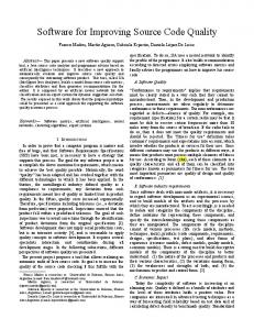
2.1.1.2 Classification of Traceability Over the years, several other terms related to requirements traceability have been established. According to [Winkler & von Pilgrim (2010)], the most common ones are pre-requirements specification, post-requirements specification, forwards, backwards, horizontal, and vertical traceability. These terms are shown in Figure 2.1 and described in detail in the following.
Figure 2.1: Dimensions & directions of traces (Source: [Winkler & von Pilgrim (2010)]) [Gotel & Finkelstein (1994)] have introduced the classification of pre-requirements specification (pre-RS) traceability and post-requirements (post-RS) traceability. Pre-RS traceability is concerned with those aspects of a requirement’s life prior to its inclusion in the RS, which means all traces that occur during elicitation, discussion, and agreement of requirements. This includes dealing with informal, conflicting, or overlapping information [Winkler & von Pilgrim (2010)]. Post-RS traceability is concerned with those aspects of a requirement’s life that result from its inclusion in the RS, which means all traces that occur during the stepwise implementation of the requirements in the design and coding phases. It includes documenting the traces of the various manual and automatic transformation steps eventually producing the system [Winkler & von Pilgrim (2010)].
10
2.1 TERMINOLOGY AND GENERAL TERMS The [IEEE Std. 830-1984] has introduced the terms backward traceability and forward traceability. Backward traceability refers to the ability to follow the traceability link from a specific artifact to its sources from which is has been derived. Forward traceability stands for following the traceability links to the artifacts that have been derived from the artifact under construction. [Ramesh & Edwards (1993)] have introduced the terms horizontal traceability and vertical traceability. These terms differentiate between traceability links of artifacts belonging to the same project phase or level of abstraction (horizontal), and links between artifacts belonging to different ones (vertical) [Winkler & von Pilgrim (2010)]. Besides the terms described above, we differentiate in this thesis between three other essential terms, as they were defined by [Winkler & von Pilgrim (2010)], and which are cited below: 1. Traceability means the ability to describe and follow the life of a software artifact in the sense of the generalized definition presented by [Gotel & Finkelstein (1994)]. 2. A trace is a piece of (implicit or explicit) information which is an indication or evidence showing what has existed or happened [Simpson & Weiner (1989)]. 3. Finally, a traceability link is, as already stated, a relation that is used to interrelate artifacts (e.g., by causality, content, etc.). Following the notation of a trace, a traceability link is a more concrete (but not the only) form of information that can be used to describe and follow certain aspects of the life of the representative software artifacts.
2.1.1.3 Representing Traceability In order to use traceability links, it is necessary to represent them in a form that is appropriate for its purpose. Several different ways exist to represent traceability links, which are also supported by tools. [Wieringa (1995)] distinguishes between three different kinds of traceability representation (traceability matrices, graphical models, cross references), while [Schwarz et al. (2009)] represent artifacts and the traceability links between them as a graph: • Traceability matrices: Traceability links are represented as a matrix. The horizontal and vertical dimensions list artifacts that can be linked. The entries in the matrix represent links between the artifacts in the matrix [Wieringa (1995)].
11
CHAPTER 2: BACKGROUND • Graphical models: Entity Relationship Models (ERM) are another way to represent traceability links. Various UML diagrams support the representation of traceability links directly embedded in the different development models [Wieringa (1995)]. • Cross references: Traceability links between artifacts are represented as links, pointers or annotations in the text [Wieringa (1995)]. • Graphs: In a graph, the nodes represent artifacts and the edges the traceability links between the artifacts [Schwarz et al. (2009)]. [Cooper et al. (2009)] provide a comprehensive overview about ways to represent traceability links between requirements and other artifacts. 2.1.1.4 Open Research Issues During the last years, much research has been done in the area of requirements traceability, and problems like the automated creation of traceability links have been studied in depth. Nevertheless, many problems still remain unsolved and more work focusing on these issues is necessary. The traceability research community recognized the demand for more research and organized a workshop on that topic. The First Workshop on Grand Challenges for Traceability (GCT’06) brought together members of the traceability community from academia, industry, and government with the goal to identify unsolved problems in the field of traceability. The outcome of the workshop was a list of various problems and grand challenges related to various aspects of traceability in software systems [Cleland-Huang et al. (2006)]. The high number of challenges and problems listed in the document shows the demand for more research work in the field of traceability. The focus of this thesis is on the creation of traceability links. Category C of problems and challenges, Supporting Evolution, is related to the creation, maintenance and evolution of traceability links. Three problems of this category related to this thesis are: C-P1
Accurate, consistent, complete, up-to-date traceability information is vital to diverse groups of stakeholders working in various domains and applications, however, current techniques for link recovery are still human intensive and error-prone (e.g., due to documentation quality, level of detail, etc.)
C-P2
For traceability links to be useful, they must reflect current dependencies between artifacts, however, the cost and effort to maintain links during system evolution is burdensome, and (as a result) the links often erode into an inaccurate state.
12
2.1 TERMINOLOGY AND GENERAL TERMS C-P4
Traceability links need to synchronously evolve with their related artifacts, however, current change management systems and link semantics are not sufficiently sophisticated to support effective evolution of traceability links.
These problems show that there is a large demand for an approach that effectively supports the creation of traceability links without much additional work required by humans and making the traceability links evolve with their related artifacts synchronously during software development. Especially the following three challenges associated to the problems above appear relevant: C-GC1
Develop link recovery techniques for textual artifacts that are at least as accurate as manual processes and are much more time- and cost-effective.
C-GC2
Develop incremental, almost real-time, traceability recovery approaches to be integrated into Integrated Development Environments.
C-GC3
Develop change management systems that effectively support the evolution of traceability links across multiple artifact types.
Furthermore, one problem from category L, Measurement and Benchmarks, as well as one problem from category J, Process, emphasize empirical evidence in the context of traceability and the need for integrating traceability in the development lifecycle, respectively: L-P1
Empirical studies are needed to demonstrate the effectiveness of traceability methods and facilitate collaborative and evolutionary work among researchers and practitioners; however, there is a lack of common experimental design, methodologies, and benchmarks.
J-P1
In order to generate and maintain quality and sound traceability information, an organizational process is required; however, traceability is often not included as an integral part of the development lifecycle.
Chapter 3 will provide a comprehensive state of the art overview about traceability between requirements and work items, work items and code, as well as requirements and code. It will also show that this topic is not sufficiently supported by current approaches. The chapter finally lists requirements for an approach trying to tackle these grand challenges (see Section 3.4). These requirements refer back to the grand challenges above and to the strengths and weaknesses found in related approaches.
13
CHAPTER 2: BACKGROUND
2.1.2 Work Items On the one hand, work items describe what has been done by project participants in the past. On the other hand, they also describe what will be done by project participants in the future. Work items have a completion status, a due date and are assigned to project participants. Typically, work items are very detailed and document an aspect of the software development work relevant in a particular moment of the project. In this thesis, we use the term work item instead of task to avoid misunderstandings with the term task used in requirements engineering. Work items can concern work related to the system that is being developed as well as the project management for the project. For example, one work item can require the project manager to define a project plan and another work item can require a developer to implement a requirement. Therefore, work items can be useful for the project manager, but also for any other team role. As described in the Project Management Body of Knowledge [PMBOK], the overall tasks and responsibilities of the project manager are to initiate, plan, execute, monitor and control, as well as close a project. Typical activities include developing the project management plan and all related component plans, keeping the project on track in terms of schedule and budget, identifying, monitoring, and responding to risks, as well as providing accurate and timely reporting of project metrics. Thus, a major activity of the project manager is to define work items and assign them to team members who are responsible for their realization. However, particular types of work items can also be created by other team members as well, e.g., a bug report or defect identified by a tester or an action item describing a particular activity for another team member.
2.2 Basic Version Control Concepts The proposed traceability approach for tracing requirements to code presented in this thesis (see Part II) builds upon a Version Control System (VCS). To provide a basis for concepts used by the traceability approach, this section first explains basic version control concepts. This includes an introduction to version control in general (see Section 2.2.1), as well as introducing the general concepts of a VCS as an implementation of version control in particular (see Section 2.2.2). After that, Subversion (SVN) is introduced and explained in detail (see Section 2.2.3), because the proposed traceability approach builds upon this popular VCS. Finally, further modern VCSs are presented (see Section 2.2.4).
14
2.2 BASIC VERSION CONTROL CONCEPTS
2.2.1 Version Control A sub-discipline of software configuration management is called version control, revision control, software versioning, or just versioning [Murta et al. (2010)]. Version control is the act of "tracking the changes of a particular artifact over time" [Leon (2004)]. In the context of code implementation, version control refers to the management of different versions of code of a project [Pilato et al. (2008)]. A version of a project depicts a snapshot of all code artifacts at a given point of time. Another term related to a version is a revision. A revision is defined as "a revised edition or form of something" [Simpson & Weiner (1989)]. In the field of version control, the term revision refers to a version that was created by changing another version. In this thesis, the term revision is often used as a synonym of the term version. Since every version is created by changing another version (with the first version being created by changing a virtual, empty version), the use of the term revision for any version is reasonable. In general, versioning has the following advantages [Pilato et al. (2008)]: • All versions of the code are archieved so that any previous version can be re-created, if necessary. • Destructive changes in the code, e.g. the accidental deletion of parts of the content of a code artifact, can be revised by recovering an older version, even if the destructive changes are already stored in the repository. • The changes implemented by a specific person at a specific point of time can be reproduced. This requires very fine-grained versioning. • The existence of more than one development branch can be managed. Different development branches allow that parts of a software are developed at the same time. For example, while a new major release is already under development, changes to the current release, e.g. bug fixes, can still be introduced and published, which is quite common for larger projects.
2.2.1.1 Development Histories & Revision Graphs In its simplest form, a development project has only one major development branch and all developers only work with the latest version. Thus, any newly created version is the successor of the latest version. A version has always only one direct successor, with the exception that the latest version has no successor yet. Version histories can be graphically
15
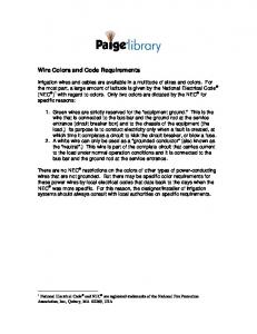
CHAPTER 2: BACKGROUND represented as revision graphs 2 . In a revision graph, the versions are represented as nodes and the "is-successor-of" relations between the versions are represented as edges. To ensure a clear layout, the nodes are usually ordered by their creation date. In case of linear development, where the latest version is always created from one predecessor, a revision graph shows a linear series of nodes (see upper part of Figure 2.2).
Figure 2.2: Revision graphs for linear development without branches (top) and with multiple development branches (bottom)
As soon as multiple development branches are introduced, a version can have more than one successor. A branch starting at a specific version, which belongs to another branch, is also called to branch, diverge or fork [Pilato et al. (2008)] from the other branch at that version. The changes done to two development branches can be recombined, which is called merging [Pilato et al. (2008)]. If branches are used, the revision graph becomes a directed acyclic graph, as shown in the lower part of Figure 2.2. In such a revision graph, a version has an additional successor for each additional branch which forked from it. A version originating from a merge of two or more branches has as many predecessors as branches were merged. Because the "is-successor-of" relation is consistent with the chronological order of versions, no directed cycles can exist. Therefore, such a revision graph with branches is represented as a directed acyclic graph.
2.2.1.2 Repositories One of the most essential elements for any software development project is a repository [Pilato et al. (2008)]. Although today the term is often used in the context of version 2
Revision Graph – http://www.eclipse.org/subversive/documentation/teamSupport/revision_ graph.php [retrieved: August, 2013]
16
2.2 BASIC VERSION CONTROL CONCEPTS control, a repository in general is just a place where the versions of the code of a project are stored [Pilato et al. (2008)]. Even if no version control is used, a repository is commonly used to allow collaboration between developers [Mason (2006)]. A repository has the following functions [Mason (2006)]: • It archieves all versions. If the data on a local machine of a developer is lost, then s/he can retrieve the code from the repository. Thus, the repository should be protected against hardware failure and other causes of data loss. • The repository is the main source for collaboration between developers as changes to an artifact are shared with other developers by updating this artifact in the repository. • New developers joining the project or established developers working at a new machine can obtain the latest versions of the code from the repository. • Depending on the type of the repository, it can offer additional services like versioning. This is especially the case for repositories managed by VCSs. The general concepts of a VCS used to manage repositories are introduced below.
2.2.2 Version Control Systems A VCS is a tool for software development that controls the different versions of the code. Non-code artifacts can also be versioned by a VCS. However, since code artifacts are the most common artifacts found in VCS repositories [Mason (2006)], the remainder of this thesis will only use the terms code artifacts or simply code. Whenever one of these terms is used, it actually refers to any possible artifact to be versioned. The basic mechanism of each VCS is that it features one or more repositories storing the revisions. A working copy is a copy of the code the user has on his/her local machine and to which s/he applies the changes [Mason (2006), Pilato et al. (2008)]. The basic operations of a VCS consist mainly of transferring data from the repository to the working copy, or vice versa. The user can retrieve revisions from the repository and upload the changes in his/her working copy to the repository, thus creating a new revision. Versioning does not necessarily mean that a VCS is used. However, VCSs are used by most of modern development projects [Pilato et al. (2008)]. Some operations, e.g., recombining two development branches, are very complicated without a VCS, because they require the calculation and recombination of changes which appeared since the divergence of the
17
CHAPTER 2: BACKGROUND branches. In case of linear development without using branches, copying all artifacts of the project to a new location to create a version would be a possibility to accomplish versioning without using any tool support. However, this is cumbersome and the reason why versioning without the tool support of a VCS is very uncommon [Mason (2006)]. Every VCS supports a basic set of commands. The creation of a new revision in the repository, by uploading the changes in the working copy, is usually called commit or checkin [Pilato et al. (2008)]. A developer commits his/her work after s/he has implemented and, in the best case, tested a piece of code. Most VCSs allow to reproduce every single revision that was committed to the repository. However, some systems allow the deletion of older revisions that are no longer needed. The operation that retrieves a certain revision from the repository and writes the data to the working copy is usually called check-out or fetch [Pilato et al. (2008)]. Most newer VCSs allow the divergence to different branches and the merging of those. Some of the systems maintain a special main branch called trunk, while others treat each branch equally. For one branch, the latest version is usually called the head revision of this branch [Pilato et al. (2008)]. Most of the time, developers are only interested in checking out the head revision of a branch to retrieve the latest changes, which is called updating [Pilato et al. (2008)]. Most VCSs also provide utilities for comparing two revisions, thus identifying the changes made between these two revisions. Another feature that is provided by most VCSs is tagging [Pilato et al. (2008)]. A revision can be tagged with a specific name so that it can be found later among the large number of revisions. Therefore, tags are used to mark special revisions, e.g. the ones that were used to build a release. The most basic approach of creating a new revision in a repository would be to transmit all artifacts to the repository and save a complete copy of all artifacts. However, this is not practicable, because it would require a large amount of disk space and the commit would take a very long time if the bandwidth of the connection to the repository is limited. Therefore, VCSs use mechanisms to reduce the amount of required disk space and network traffic. A common possibility to reduce disk space and network traffic, which is used by the majority of VCSs, is only to store the differences between two revisions, which is called diff or delta [Pilato et al. (2008)]. These deltas contain detailed information about what was changed in the artifacts of the revisions. If the versioned artifacts are text-based, such as code artifacts, the deltas are very fine-grained so that even a single character changed in a line of code can be identified [Pilato et al. (2008)]. To ensure data integrity, most VCSs provide guarantees known from database management systems. For example, most VCSs guarantee parts of the ACID (atomicity, consistency,
18
2.2 BASIC VERSION CONTROL CONCEPTS isolation, durability) properties for any transaction, similar to commits. Either a commit is executed thoroughly and successfully, or the commit is aborted and no change is made to the repository (atomicity). Two people cannot commit concurrently, or if they can, the system guarantees sequentially consistent semantics (isolation). Some VCSs also protect against other threats to data integrity, e.g. malicious changing of data.
2.2.3 Subversion An example of a VCS is Subversion (SVN). Historically, it is one of the most important and popular VCSs [Pilato et al. (2008)] and the UNICASE Trace Client presented in this thesis (see Chapter 5) is based upon it. SVN, now Apache Subversion3 , was initially created as an open source project at CollabNet in the year 2000. The explicit goal of SVN was to overcome some limitations and design flaws of previous VCSs [Collins et al. (2004)], especially the Concurrent Versions System (CVS)4 [Grune (1986)]. According to [Pilato et al. (2008)], a SVN repository consists of one directory tree starting at a specified root. Different projects are usually stored in the same SVN repository by creating sub-folders in the repository’s root folder. Instead of versioning single artifacts, a revision in SVN may represent an entire directory tree of artifacts. SVN uses global revision numbers to identify revisions, starting from zero and increasing the revision number by one for each successive commit [Mason (2006), Pilato et al. (2008)]. Only artifacts that are actually changed in a commit receive the new revision number of the commit, others retain their old ones. The revision number of a directory is calculated as the highest revision number of its contents. The reason why unchanged artifacts retain their old revision number after a commit is because a commit does not include an update in SVN. Thus, these artifacts could have been changed by other people in the meantime. If their revision number was updated, their content should be updated as well to maintain consistency. Since no update is performed during commit, they are not updated. Once an update to the latest revision is done, all artifacts’ revisions are updated to the latest revision number even if they have not changed. This is done to flag these artifacts as up-to-date. Since trees have a revision, too, it is very easy to describe a specific revision of the whole project by stating the revision number of the root directory of the project. In contrast, in CVS a revision of a project can only be specified by stating a certain date and then searching the revision for each artifact which was the latest at that date. The improved support for versioning of projects is one of SVN’s key advantages over CVS. 3
4
Apache Software Foundation. Apache Subversion – http://subversion.apache.org [retrieved: August, 2013] Free Software Foundation, Inc.
Concurrent Versions System – http://savannah.nongnu.org/
projects/cvs [retrieved: August, 2013]
19
CHAPTER 2: BACKGROUND SVN stores meta data for each folder in a hidden sub-folder called .svn. This folder also contains the base version of each artifact resulted from the last check-out or update operation. While this increases disk usage, it allows the execution of some commands locally instead of having to query the remote repository, which would introduce network delay. For example, the changes in the working copy can be calculated locally. Also, local changes can be reverted without querying the repository. SVN also uses deltas to save disk space. Furthermore, it is a client-server based VCS, which means the working copy is linked to exactly one remote repository. SVN does not offer the concept of branches or tags directly. However, it is able to support them by using the copy command [Pilato et al. (2008)]. This command makes a so-called cheap copy of an artifact or directory in the repository. A cheap copy starts out as just a symbolic link to the copied directory. Once changes are done to the copy, these changes are stored as deltas only. Thus, although the cheap copy is shown as an own directory with all the contents of the source directory in the repository, it does not take up the disk space of a complete copy (at least not in the repository, only in the working copy). A branch can be created by cheap-copying the whole project folder to another location. Developers who want to work on the branch check out the destination where the artifacts were copied to and introduce their changes on this destination. Since the resulting copy is not explicitly marked as branch, a default directory structure is recommended to identify branches and tags. The recommended project structure in an SVN repository is to have a directory for each project in the root directory of the repository. In this directory, the folders trunk, branches, and tags are created [Pilato et al. (2008)]. The trunk folder contains the main development branch of the project. A branch is created by cheap-copying the content of the trunk folder into a new subfolder in the branches directory, having the branch’s desired name. A tag is created the same way, but copied into the tags folder. Thus, a tag in SVN is basically the same as a branch, however, nobody should commit to this tag, which would make it a branch. Access control mechanisms can be used to prevent users from committing to the tags directory. To check out a tag or branch without having to check out the whole directory, which would also take additional disk space, SVN provides the switch command to replace the working copy with the specified directory or revision [Pilato et al. (2008)].
2.2.4 Further Modern Version Control Systems VCSs can be divided into two categories: centralized and decentralized. If one central repository is stored on a globally accessible server, the VCS is called centralized. For example, SVN is a centralized VCS. However, if each developer has also a local repository
20
2.2 BASIC VERSION CONTROL CONCEPTS on his/her machine, the VCS is called decentralized, distributed or peer-to-peer. If the VCS is distributed, data is exchanged by pulling or pushing data from one repository to another [Loeliger (2012)]. Popular examples for decentralized VCSs include Git and Mercurial. In addition, platforms exist that allow the free hosting of projects, e.g., GitHub5 supporting Git, and Google Code6 supporting SVN and Mercurial. Usually, VCSs directly integrate themselves into integrated development environments via external plug-ins. For example, for Eclipse various plug-ins exist that integrate centralized and decentralized VCSs: Subversive7 and Subclipse8 for SVN, EGit9 for Git and MercurialEclipse10 for Mercurial. In this thesis, decentralized VCSs are not further explored, because the presented traceability approach is based on SVN. In particular, the UNICASE Trace Client integrates with the Subversive plug-in for Eclipse to provide its functionality to link work items to revisions. The decision for SVN and Subversive is elaborated in detail in Section 5.3.3.
5
GitHub – http://www.Github.com/ [retrieved: August, 2013] Google Code – http://code.google.com/ [retrieved: August, 2013] 7 Subversive – http://www.eclipse.org/subversive/ [retrieved: August, 2013] 8 Subclipse – http://subclipse.tigris.org/ [retrieved: August, 2013] 9 EGit – http://www.eclipse.org/egit/ [retrieved: August, 2013] 10 MercurialEclipse – https://bitbucket.org/mercurialeclipse/ [retrieved: August, 2013] 6
21
Chapter
3
State of the Art Knowledge of what is does not open the door directly to what should be. – Albert Einstein, 1879-1955 – In this chapter, we provide an overview about the state of the art of traceability between requirements, work items, and code. We conducted a systematic literature review divided in two separate searches. The first search identified existing research creating and using links between requirements and work items (see Section 3.2.1) as well as between work items and code (see Section 3.2.2). The second search looked for existing research creating and using links between requirements and code (see Section 3.2.3). To reduce the number of necessary searches, we combined the search for existing research on work items into only one search by using different search terms, either focussing on requirements and work items or on work items and code. In our systematic literature review, we had the following research questions for our two searches: • RQ1: How are the links between requirements, work items, and code created? • RQ2: How are the links between requirements, work items, and code used? • RQ3: What supporting tools are used for the creation or use of links? • RQ4: What type of empirical evidence exists for the benefits of the links? After presenting our research method (see Section 3.1), we provide an overview about the identified approaches (see Section 3.2). The research questions are picked up again in the discussion (see Section 3.3) to synthesize the results of the systematic literature review.
22
3.1 RESEARCH METHOD
3.1 Research Method We used the guidelines of [Kitchenham & Charters (2007)] for our search strategies and documentation. The aim was to identify major contributions in the three research areas of traceability between: a) requirements and work items, b) work items and code, and c) requirements and code. [Kitchenham & Charters (2007)] recommend that a systematic literature review has the following characteristics: • a defined search strategy • a broad collection of search sources • a defined search string, based on a list of synonyms combined by ANDs and ORs • a strict documentation of the search • explicit inclusion and exclusion criteria • paper selection should be checked by two researchers We fulfilled all these criteria, except that the paper selection was only checked by one researcher. The review followed a structured process with an initial phase with three steps (1 - generation of search string, 2 - identification of research, 3 - first exclusion round) and the refinement phase with two steps (4 - second round of exclusion, 5 - consolidation of results). The results for each step are discussed below.
3.1.1 Generation of Search Strings Since we conducted two separate searches, we generated two different search strings. The first search string covers research for creating and using links between requirements and work items as well as between work items and code. The second search string covers research for creating and using links between requirements and code. Search for Work Item Literature The final search string for work item literature had three terms (see in Table 3.1). The first term is divided in two terms, each focusing either on requirements or code. We used term 1a or 1b to find research for creating and using links between requirements and work items or between work items and code, respectively. The second term ensures that traceability links between the artifacts are considered. Furthermore, we explicitly searched for papers from the Mining Software Repositories11 (MSR) community by using the terms "mining" and "msr" in term 2, because in this research area data mining techniques are 11
Mining Software Repositories – http://www.msrconf.org/ [retrieved: August, 2013]
23
CHAPTER 3: STATE OF THE ART often applied to create or use links between work items and code. The third term is a collection of various synonyms for work item. All three terms had to appear in the title, abstract or keywords of the papers. Table 3.1: Derived Search Terms for Work Items Search Terms Term 1a Term 1b
requirement OR "system specification"
Restriction Title, Abstract,
code OR repository OR revision OR "version control system"
Keywords Title, Abstract,
OR vcs
Keywords AND
Term 2
Term 3
trace OR traceability OR link OR relation OR mining OR msr
Title, Abstract, Keywords
AND "work item" OR "action item" OR "bug report" OR "change
Title, Abstract,
request" OR ticket OR "project management"
Keywords
Search for Requirements and Code Literature The final search string for requirements and code literature had four terms (see in Table 3.2). The first term addresses requirements, while the second term addresses code. The third term ensures that traceability links between the artifacts are considered. However, it differs from term 2 in Table 3.1 because "mining" and "msr" are only used by MSR in conjunction with work items, which is not the focus of this search. The fourth term is a collection of various synonyms to create traceability links. To reduce the number of similar terms required in the search string, we used wild cards (*), e.g., creat* to cover terms like creation, create, creating etc. All terms had to appear in the title, the abstract or keywords of the papers. Table 3.2: Derived Search Terms for Requirements and Code Search Terms Term 1
Term 2
requirement OR "system specification"
Restriction Title, Abstract, Keywords
AND code OR repository OR revision OR "version control system"
Title, Abstract,
OR vcs
Keywords AND
Term 3
Term 4
trace OR traceability OR link OR relation
Title, Abstract, Keywords
AND creat* OR infer* OR deriv* OR deduc* OR automat* OR algorithm
Title, Abstract,
OR retriev*
Keywords
24
3.1 RESEARCH METHOD
3.1.2 Identification of Research We want to create a comprehensive picture of the state of the art of traceability between requirements, work items, and code using the two search strings. Therefore, we used different kinds of sources. We used the domain-specific publication sources IEEE12 , ACM13 , and SpringerLink14 . To also ensure coverage of research in other less dominant sources, we included the source ScienceDirect15 covering several other domain-specific sources. These four sources also include research from the MSR community. All searches were executed in February 2013. The first search for work item literature retrieved 439 hits, while the second search for requirements and code literature retrieved 968 hits.
3.1.3 First Exclusion Round Following the recommendation of [Kitchenham & Charters (2007)], we did an initial selection based on publication title and abstract, which lead to 41 results for the first search and 65 results for the second search. Papers were only included if they explicitly concerned either requirements, work items, or code in the title or abstract. The removing of duplicate results lead to 32 for the first search and 59 results for the second search. As a total of 91 publications are too many for a thorough analysis, we conducted a second exclusion round.
3.1.4 Second Exclusion Round In the second exclusion round, we looked at the abstract, introduction and conclusion sections of the papers. We consciously included the conclusion section, as the quality of abstracts was in some cases not very high. Papers were excluded if they did not explicitly concerned either requirements, work items, or code. Papers were also excluded if they had a different focus than or were out of the context of traceability in software engineering or development. For example, some papers considered traceability in the development of health care products. In the end, for work item literature we identified a total of 17 papers as relevant (requirements – work items = 5; work items – code = 12), while for the requirements and code literature we identified a total of 34 papers as relevant.
3.1.5 Consolidation of Results The resulting 51 papers were analyzed regarding the four research questions on the creation and use of links between the artifacts, available tool support and evaluation. 12
IEEE Xplore – http://ieeexplore.ieee.org/Xplore/home.jsp [retrieved: August, 2013] ACM – http://dl.acm.org/ [retrieved: August, 2013] 14 SpringerLink – http://www.springerlink.com/ [retrieved: August, 2013] 15 ScienceDirect – http://www.sciencedirect.com [retrieved: August, 2013] 13
25
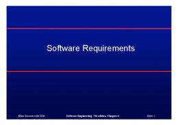
CHAPTER 3: STATE OF THE ART In the following Section 3.2, we provide an overview about all approaches creating and using traceability links between requirements, work items, and code identified by our systematic literature review. Figure 3.1 summarizes the identified number of papers.
Work Items and Code 12 34
Requirements and Code
5 Requirements and Work Items Figure 3.1: Number of Approaches for Creating and Using Traceability Links between Requirements, Work Items, and Code The overall findings of our systematic literature review are discussed in Section 3.3. Based on the findings of our systematic literature review, we derived requirements for a new traceability approach (see Section 3.4) overcoming the limitations of previous approaches.
3.2 Overview of Approaches Section 3.2.1 discusses the five approaches concerning traceability between requirements and work items. Section 3.2.2 presents the twelve approaches for traceability between work items and code, while Section 3.2.3 provides an overview about the 34 approaches for tracing requirements and code. For all approaches, first the creation of links with available tool support and evaluation is discussed, followed by the usage of links with available tool support and evaluation. At the end of each Section 3.2.1, 3.2.2, and 3.2.3, the main findings are summarized. In the following sections, we report about the quality of the created traceability links using two measures, precision and recall, which are two standard metrics used in IR [Frakes & Baeze-Yates (1992)]. Precision is the fraction of retrieved instances that are relevant, while recall is the fraction of relevant instances that are retrieved. The metrics are computed as follows:
P recision =
RelevantLinks ∩ RetrievedLinks RelevantLinks ∩ RetrievedLinks Recall = RetrievedLinks RelevantLinks (3.1) (3.2)
26
3.2 OVERVIEW OF APPROACHES
3.2.1 Requirements and Work Items Links between requirements and other artifacts are extensively studied in the requirements engineering community, e.g., in [Cleland-Huang et al. (2012c)]. Work items represent explicit knowledge about the processes executed in the project. This knowledge is gathered, updated and detailed continuously over time. Only very few approaches consider links between requirements and work items, which are discussed in the following. Creation of Links between Requirements and Work Items (RQ1, RQ3, RQ4) In Table 3.3, the approaches for creating links between requirements and work items are summarized. Link creation, tool support, and empirical evidence are emphasized. Table 3.3: Approaches for Creating Links Between Requirements and Work Items Approach
Link Creation
Tool Support
Empirical Evidence
Manual
UNICASE
Academic
Automatic
RETRO
Industrial
[Helming et al. (2009a)] [Helming et al. (2009b)] [Helming et al. (2009c)] [Helming et al. (2010)] [Yadla et al. (2005)]
All approaches use textual requirements as development artifacts. We found four different approaches by [Helming et al. (2009a), Helming et al. (2009b), Helming et al. (2009c), Helming et al. (2010)]. However, in all those approaches traceability links between requirements and work items are only created manually. They implemented their approach in the model-based CASE-tool UNICASE, which is an application based on the Eclipse framework and is developed in an open-source project16 . UNICASE is capable of storing all kinds of system and project knowledge and the traceability links between them in a single environment. However, the authors did not provide empirical evidence that focuses explicitly on the creation of links, only on the usage of links, which is discussed afterwards. The approach by [Yadla et al. (2005)] supports the automatic linking of requirements to bug reports as a special kind of work items, using Information Retrieval (IR) techniques. It is implemented in the tool RETRO (REquirements TRacing On-target). Basically, the approach uses IR techniques to search for similarities of texts in requirements and in bug reports. The search is not automatically applied as soon as a bug report is created, but a team member can manually initiate the approach at any time during the project. They evaluated their approach based on two datasets for a NASA scientific instrument. They found that for the first dataset, precision (fraction of retrieved instances that are relevant) 16
UNICASE open-source project – http://www.unicase.org/ [retrieved: August, 2013]
27
CHAPTER 3: STATE OF THE ART is 69% and recall (fraction of relevant instances that are retrieved) is 85%, while for the second dataset precision is 99% and recall is 70%. Results in this range are very good and comparable to manual linkage [Maeder & Gotel (2012)]. Usages of Links between Requirements and Work Items (RQ2, RQ3, RQ4) Table 3.4 provides an overview about the usage of links between requirements and work items. Links from work items are typically used to support comprehension of the work item. For example, a developer navigates from a work item describing an implementation task to the corresponding requirements to gather detailed information about his/her work. Table 3.4: Approaches for Using Links Between Requirements and Work Items Approach [Helming et al. (2009a)] [Helming et al. (2009b)]
Usage
Tool Support
Empirical Evidence
UNICASE
Academic
UNICASE
Academic
UNICASE
Academic
Direct Navigation, Comprehension Support, Project Reporting Up-to-date Requirements Specification
[Helming et al. (2009c)] [Helming et al. (2010)]
Change Awareness Automatic Assignment of Work Items to Developers
[Helming et al. (2009a), Helming et al. (2009b)] describe a case study analyzing data of the development project of UNICASE. They conducted two analyses regarding the direct navigation as well as comprehension support for project managers. In the first analysis, they observed that as long as work items and requirements stand in meaningful relations to each other (e.g. a work item is referencing a requirement in its textual description), users navigate between them, even when there are no explicit links between them. In the second analysis, they studied the navigation distance between the work items and requirements, which is the number of clicks required to get from one artifact to another. They confirmed the expected benefit of links, namely that developers achieved significantly lower navigation distances for linked artifacts than for non-linked artifacts. The aggregation of links can provide further comprehension support. In another analysis, [Helming et al. (2009a)] studied project reporting. UNICASE provides an overview of the requirements and the number of associated open work items over time. A preliminary analysis of a few requirements showed that this overview realistically visualizes the team status, similar to burn-down charts in SCRUM. The authors also studied whether requirements linked to work items have a higher level of actuality, meaning that developers keep the requirements related to their work items more up-to-date. They showed that the number of changes for linked artifacts is significantly higher than for non-linked artifacts.
28
3.2 OVERVIEW OF APPROACHES [Helming et al. (2009c)] studied change awareness, which supports team members in keeping up with changes that were made to development artifacts by others. Change notification strategies are used to inform the team members about changes relevant to them. The notification strategy of Helming et al. is based on the traceability links between requirements and work items. For example, a change of a functional requirement by one user would lead to the notification of another user assigned to a work item related to this functional requirement. Based on data of a big student project with a real customer they showed that this traceability-based notification strategy results in a low number of notifications with a high rating of user satisfaction. According to the [PMBOK], one of the most important tasks of a project manager in a software development project is the initial assignment of work items to the responsible developers. In case that the software development project already comprises requirements linked to work items, new work items can be automatically assigned to developers who have worked on similar requirements in the past. [Helming et al. (2010)] applied existing machine learning techniques as well as a novel approach relying on the links to assign work items to developers. The latter approach can clearly only be applied if links are available. They evaluated all approaches on three large UNICASE projects. The novel approach outperformed the existing approaches whenever it was applicable. Summing up, traceability links between requirements and work items are mainly created manually, which is shown by the four approaches of Helming et al. This is reasonable, as a project manager needs to plan the realization of the requirements and manually link the corresponding requirements to the work items. However, [Yadla et al. (2005)] have shown that links between requirements and bug reports (a special type of work item) can be created automatically. Traceability links between requirements and work items are typically used to support comprehension of work items, e.g., by directly navigating between the artifacts [Helming et al. (2009a), Helming et al. (2009b)], or by providing change awareness [Helming et al. (2009c)].
3.2.2 Work Items and Code Many commercial software development projects as well as open source projects (e.g., Eclipse, Apache, etc.) use issue trackers17 , together with a centralized VCS like Subversion, or the increasingly popular Git. A major focus of the MSR community is to apply data mining techniques to analyze the vast amounts of data stored in issue tracking systems and VCSs. Our systematic literature review also found the paper by [Hassan (2008)], 17
Skerrett, I. The Eclipse Foundation: The Eclipse Community Survey 2013 – http://eclipse.org/ org/press-release/20130612_eclipsesurvey2013.php [retrieved: August, 2013]
29
CHAPTER 3: STATE OF THE ART which presents a brief history of MSR and discusses the achievements so far. The specific approaches to create links between work items and code are discussed in the following. Creation of Links between Work Items and Code (RQ1, RQ3, RQ4) Table 3.5 provides an overview of approaches and tools creating links, sorted according to their year of publication. Although [Nguyen et al. (2010)] do not present an approach for creating links, we identified it as relevant and included it in the discussion of this section because they present empirical evidence for creating links between work items and code. Table 3.5: Approaches for Creating Links Between Work Items and Code Approach
Link Creation
Tool Support
Empirical Evidence
[Bachmann et al. (2010)]
(Semi-) Automatic
Linkster
Open Source
[Sureka et al. (2011)]
Automatic
Experimental tool
Open Source
[Bangcharoensap et al. (2012)]
Automatic
-
Open Source
[Davies et al. (2012)]
Automatic
-
Open Source
[Nguyen et al. (2010)]
-
-
Open Source
[Bachmann et al. (2010)] present an approach that helps to automatically link revisions and work items after development. They focus on bug reports, which are a special kind of work items. They implemented a tool called Linkster that provides multiple queryable, browseable, time-series views of VCS history and bug reports to support the (semi-) automatic creation of links between revisions and work items after development. They engaged an expert core developer from the Apache open source project to classify six full weeks of the Apache VCS history using Linkster. They used this dataset consisting of 493 revisions and 103 bug reports to analyze the connections between the bug reports and revision data. The authors had four findings. First, not all fixed bugs are stored in issue trackers. Some are discussed (only) on the mailing list. Second, to fix a bug in an Apache release, multiple similar revisions by different developers are needed. Third, developers sometimes fix bugs that are only reported in other projects’ issue trackers, rather than in their own, and vice versa. And fourth, even if the authors had linked all revisions to bug reports, the cause of changing the code would still remain unspecified in some cases. [Sureka et al. (2011)] present a novel method to automatically recover traceability links between standalone bug reports and code artifacts within a VCS. In contrast to existing research (e.g. [Bachmann et al. (2010)]) that primarily used regular expressions, their approach uses formal mathematical foundation (primarily based on probability theory). They performed a series of experiments on an evaluation dataset from the open source projects of Apache and WikiMedia consisting of 8470 bug reports and 10159 revisions. The
30
3.2 OVERVIEW OF APPROACHES reported precision results (manual validation by visually inspecting each case carefully) with precision between 88%-95% show the feasibility of their approach. [Bangcharoensap et al. (2012)] propose a method to identify code artifacts that may contain a bug described in an initial bug report description. This study uses three mining approaches: text mining, code mining, and change history mining. In a first step, the text mining approach measures the textual similarities between the description of a bug report and all code artifacts to identify a ranked list of code artifacts. In a second step, the code mining and change history mining approaches are used to further reduce the potential list of erroneous code artifacts. They evaluated their approach using Eclipse platform project data consisting of 2950 bug reports and 48764 code artifacts, achieving an accuracy of about 53%. During their study, the authors had several interesting findings. First, the study revealed that bug reports that contained a short description and many specific words were easier to use to locate the buggy code artifacts. Second, they identified that developers do not always change a single code artifact to fix a bug. According to their analysis, for 43% of the bug reports, developers changed two or more code artifacts to fix the bugs, which is in line with the findings made by [Bachmann et al. (2010)]. [Davies et al. (2012)] propose an approach that measures the similarity between the text used in the bug report and the text of other already fixed bug reports together with the fixed code. For their evaluation, the authors combine their approach with approaches only measuring the textual similarity between bug report descriptions and code artifacts (e.g. [Bangcharoensap et al. (2012)]). They evaluated this combined approach using 372 bug reports and 14375 methods in the code from four open source projects (ArgoUML, JabRef, jEdit, muCommander). The authors showed that their own approach is not very effective when used alone, but showed statistical significant improvements when used in combination with approaches measuring the textual similarity between bug report descriptions and code artifacts. However, the authors did not report about precision and recall of the created links. [Nguyen et al. (2010)] did not suggest a new approach, but studied linkage bias and tagging bias. Linkage bias either means that a bug report is linked to the wrong code or no code at all. Tagging bias means that not all bug reports in an issue-tracking system actually represent bugs. Instead, developers often use issue-tracking systems to track other issues such as tasks, decisions, and enhancements. Therefore, using such data might lead to incorrect bug counts for the different parts of a software system. The authors used a near-ideal dataset from the IBM Jazz project consisting of 13367 fixed bug reports and examined the aforementioned biases. They found that even in this ideal setting, both
31
CHAPTER 3: STATE OF THE ART types of biases do exist in the dataset. They argue that linkage bias is more likely due to the software development process rather than being a side effect of the linking heuristics. The authors also found that, even under tagging bias, existing bug prediction models will still perform almost as if there is no bias. Their results suggest that these biases may exist in software data as properties of the software process itself and that these biases should not stop researchers from using such datasets. Usages of Links between Work Items and Code (RQ2, RQ3, RQ4) Links between work items and code can be used in various ways (see Table 3.6). Table 3.6: Approaches for Using Links Between Work Items and Code Empirical
Approach
Usage
Tool Support
[Maeder & Egyed (2011)]
Direct Navigation
Experimental tool
Academic
-
Open source
[Kadgi & Poshyvanyk (2009)] [Canfora & Cerulo (2005)] [Canfora & Cerulo (2006)]
Automatic Assignment of Work Items to Developers Impact Analysis
[Gethers et al. (2011a)]
Jimpa (Eclipse plug-in) Experimental tool
[Gethers et al. (2012)]
Evidence
Open Source Open Source
[Maeder & Egyed (2011)] conducted a controlled experiment with 52 subjects (students of computer science) performing 315 maintenance tasks on two third-party development projects: half of the tasks with and the other half without traceability navigation. They concluded that the mere existence of traceability links between work items and code has a profound effect on the performance (21% faster) and quality (60% better) of the implementation tasks. Furthermore, the existence of links fundamentally changed the way subjects navigated through the code. They found that the subjects relied predominantly on traceability navigation when it was available, displacing the manual search navigation in most cases. The subjects adopted traceability immediately as their major way of navigation within the code, right from the first performed task, even without training. The other approaches revealed in our search do not presume links. Instead, they create temporary links between work items and code for specific usage. The empirical evidence focuses on the correctness of the approaches and not on the usage of the links. [Kadgi & Poshyvanyk (2009)] present an approach that combines two existing techniques to recommend developers that are best suited to help with an incoming change request, which is a special type of work item. Using IR techniques they identify code artifacts that
32
3.2 OVERVIEW OF APPROACHES are similar to the change request and then choose developers who contributed substantial changes to these code artifacts. They evaluated their approach on data consisting of change requests and code from the open source project KOffice. However, their evaluation is very preliminary, as only one change request was analyzed. [Canfora & Cerulo (2005), Canfora & Cerulo (2006)] propose an approach for deriving a set of code artifacts impacted by a proposed textual change request. This is helpful for developers to identify code to work on, as well for project managers to estimate the effort of a change request. Their approach uses data stored in a VCS and an issue tracking system and it is implemented in the tool "Jimpa", which is a plug-in for Eclipse. The method exploits IR techniques to identify code artifact revisions impacted by past change requests similar to the actual one. They showed by a case study consisting of four open source projects (kcalc, kpdf, kspread, Firefox) that the set of code artifacts returned by their approach is correct with a precision no less than 30% in some cases and reaches a maximum of 78%, while recall ranges from 67%-98%. In a follow-up work to Kadgi & Poshyvanyk and Canfora & Cerulo, [Gethers et al. (2011a), Gethers et al. (2012)] also present an approach to perform impact analysis from a given change request to code artifacts. The approach uses a combination of IR, dynamic analysis and mining software repositories techniques. In addition, this approach uses contextual information such as the execution traces of the code and an initial code artifact that was verified for change, meaning that this code artifact needs to be definitely considered. To validate their approach, the authors conducted an empirical evaluation on four open source projects (ArgoUML, JabRef, jEdit, muCommander). Their results indicate that their approach shows statistically significant improvements over the approaches which only rely on the textual description of the change requests. In certain cases, an improvement of 17% in precision and 41% in recall was gained. Summing up, traceability links between work items and code are created mainly automatically (cf. [Sureka et al. (2011), Bangcharoensap et al. (2012), Davies et al. (2012)]). The study by [Maeder & Egyed (2011)] provides empirical evidence for the usefulness of using links between work items and code. Furthermore, research by [Canfora & Cerulo (2005), Canfora & Cerulo (2006)] and [Gethers et al. (2011a), Gethers et al. (2012)] shows that these links are useful during impact analysis.
3.2.3 Requirements and Code In the following section, an overview about approaches creating and using traceability links between requirements and code is provided.
33
CHAPTER 3: STATE OF THE ART Creation of Links between Requirements and Code (RQ1, RQ3, RQ4) The manual creation of traceability links between requirements and code is error-prone, time consuming, and complex [Spanoudakis & Zisman (2004)]. Therefore, research focuses mainly on (semi-) automatic and automatic approaches. In Table 3.7, the approaches for creating links between requirements and code are summarized. The type of link creation, tool support, and empirical evidence with precision and recall are emphasized. To provide a chronological overview, the approaches are ordered and discussed according to their year of publication and their type of automation. The large majority of 89% (26 of 29) of approaches use automatic techniques, while only two approaches use manual techniques and one approach uses a (semi-) automatic technique. Furthermore, the 26 automatic approaches are discussed according to the used technique, e.g., IR, execution trace, machine learning, transformation or inference. Execution Trace:
Machine Learning:
[Egyed & Gruenbacher (2002)]
[Grechanik et al. (2007)]
[Egyed (2003)]
Transformation:
[Egyed et al. (2007)]
[Kalnis et al. (2010)]
[Eisenberg & De Volder (2005)]
Inference: [Nagano et al. (2012)] 11
4
1
19
Information Retrieval: [Antoniol et al. (2000a)] [Antoniol et al. (2000b)] [Antoniol et al. (2000c)] [Antoniol et al. (2002)] [Marcus & Maletic (2003)] [De Lucia et al. (2004)] [De Lucia et al. (2005)] [Marcus et al. (2005)] [Lin et al. (2006)] [De Lucia et al. (2007)] [De Lucia et al. (2008)] [Eaddy et al. (2008)] [Gethers et al. (2011b)] [Ali et al. (2011a)] [Ali et al. (2011b)] [Bavota et al. (2012)] [Ali et al. (2013)] [Niu et al. (2012)] [Charrada et al. (2012)] Figure 3.2: Approaches for Automatically Creating Traceability Links between Requirements and Code
34
3.2 OVERVIEW OF APPROACHES From the 26 approaches for automatic creation of traceability links between requirements and code, a majority of 73% (19 of 26) uses IR techniques, while only about 15% (4 of 26) use execution trace analysis (see Figure 3.2). The remaining approaches either use machine learning, transformation, or inference. Table 3.7: Approaches for Creating Links Between Requirements and Code Approach
Link Creation
Tool Support
Empirical Evidence
Pr.
Re.
Automatic Approaches Using Information Retrieval [Antoniol et al. (2000a)] [Antoniol et al. (2000b)] [Antoniol et al. (2000c)]
Automatic (PM)
Experimental tool
Industrial
54 58%
60 64%
[Antoniol et al. (2002)]
Automatic (VSM)
Experimental tool
Industrial
49%
50%
[Marcus & Maletic (2003)] [Marcus et al. (2005)]
Automatic (LSI)
-
Industrial
54%
93.5%
[De [De [De [De
Automatic (LSI)
ADAMS, ADAMS Re-Trace
Academic
29%
52%
[Lin et al. (2006)]
Automatic (PM)
Poirot
Academic, Industrial
-
-
[Eaddy et al. (2008)]
Automatic (IR)
CERBERUS
Open Source
75%
73%
[Gethers et al. (2011b)]
Automatic (PM, VSM, JS, RTM)
Experimental tool
Academic
40%
-
[Ali et al. (2011a)] [Ali et al. (2011b)] [Ali et al. (2013)]
Automatic (IR)
Experimental tool
Open Source
25 54%
12 16%
[Bavota et al. (2012)]
Automatic (VSM)
TraceME
-
-
-
[Niu et al. (2012)]
Automatic (IR)
RETRO/Poirot
Open Source
26%
91%
Automatic (IR)
Experimental tool
Open Source
79%
-
Lucia Lucia Lucia Lucia
et et et et
al. al. al. al.
(2004)] (2005)] (2007)] (2008)]
[Charrada et al. (2012)]
Automatic Approaches Using Execution Trace Analysis [Egyed & Gruenbacher (2002)]
Automatic (execution trace)
Trace Analyzer
Industrial
-
-
[Egyed (2003)] [Egyed et al. (2007)]
Automatic (execution trace)
STRADA
Open Source
-
-
[Eisenberg & De Volder (2005)]
Automatic (execution trace)
Experimental tool
Open Source
-
-
Automatic Approaches Using Other Techniques [Grechanik et al. (2007)]
Automatic (machine learning)
LeanArt
Open source
34 87%
-
[Kalnis et al. (2010)]
Automatic (transformation)
Experimental tool
-
-
-
[Nagano et al. (2012)]
Automatic (inference)
-
Industrial
20%
70%
Manual and (Semi-) Automatic Approaches [Ratanotayanon et al. (2009)]
Manual
Zelda
Open Source
90%
73%
[Omoronyia et al. (2009)]
(Semi-) automatic (capture)
Experimental tool
-
-
-
[Egyed et al. (2010)]
Manual
Experimental tool
Open Source
-
-
35
CHAPTER 3: STATE OF THE ART Automatic Approaches Using Information Retrieval [Antoniol et al. (2000a), Antoniol et al. (2000b), Antoniol et al. (2000c)] presented an approach for recovering traceability between high level artifacts (e.g. requirements) and low level artifacts (e.g. code). An assumption of their work is that developers use "meaningful names for code items" [Antoniol et al. (2000b)], e.g., classes, methods, functions, variables and types. They believe that the application-domain knowledge that developers process when writing the code is often captured in these program items. Therefore, the analysis of these program items can help to link high-level concepts expressed in free text, such as requirements, with low-level concepts, such as code, and vice versa. Under the above assumption, the knowledge of existing traceability links can be exploited. The method can be fully automated and human intervention is only required to confirm or reject automatically recovered traceability links. The approach uses as IR method a Probabilistic Model (PM) consisting of a set of complex mapping equations based on stochastic statistic models. Basically, the approach is automatically looking for textual similarity between textual representation of the requirements and the code. The approach was evaluated using data from an industrial hotel management system consisting of 16 functional requirements and 95 classes containing 20 KLOC (KLOC = thousand lines of code). The recovery process focused on the 60 classes implementing the user interface of the software system. The peak performance of the approach achieved a precision between 54%-58% and a recall between 60%-64%. In a further work, [Antoniol et al. (2002)] extended their approach from above by applying a Vector Space-Based Model (VSM) and compared the results to the previously presented approach using a PM. They conducted two case studies. While the first case study focused on tracing C++ code to manual pages, the second case study focused to trace Java code to functional requirements. The second case study was again using the data from the industrial hotel management system. The new approach using VSM achieved a precision of 49% and a recall of 50%, achieving slightly lower results than the approach using PM from their previous evaluation. [Marcus & Maletic (2003), Marcus et al. (2005)] applied Latent Semantic Indexing (LSI) to the data of [Antoniol et al. (2000a), Antoniol et al. (2000b), Antoniol et al. (2000c)], again using precision and recall for evaluation. They improved the results by Antoniol et al., achieving a prevision of 54% and a recall of 93.5%. [De Lucia et al. (2004), De Lucia et al. (2007)] extended a tool called ADAMS (ADvanded Artefact Management System) with LSI. The authors call this extension ADAMS Re-Trace and it is presented in detail in [De Lucia et al. (2005), De Lucia et al. (2008)].
36
3.2 OVERVIEW OF APPROACHES ADAMS is an artifact-based process support system for the management of human resources, projects, and software artifacts. In particular, ADAMS provides support for traceability and event-based notification of changes, thus increasing the context awareness during the evolution of software artifacts. In the basic version of ADAMS, the software engineer is in charge of manually maintaining traceability links between software artifacts. The extended tool ADAMS Re-Trace highlights the candidate links not identified yet by the software engineer and the links already identified, but missed by the tool, probably due to inconsistencies in the usage of domain terms in the traced software artifacts. The authors conducted a case study using data from a software project developed by undergraduate students consisting of 30 use cases and 37 code artifacts [De Lucia et al. (2004)]. ADAMS is not only able to store use cases and code artifacts, but also other artifacts, e.g., interaction diagrams and test cases. De Lucia et al. achieved better results when tracing interaction diagrams onto test cases (a precision of 33% and a recall of 95%) and worse results when tracing use cases onto code artifacts (a precision of 29% and a recall of 52%), probably due to the higher abstraction of the two types of artifacts. [Lin et al. (2006)] present Poirot, a web-based tool supporting traceability of distributed heterogeneous software artifacts. A PM is used as IR technique to dynamically generate traces between various types of software artifacts, including requirements and code. These artifacts can be stored in distributed third party case tools such as IBM DOORS, IBM Rational Rose, and VCSs. Poirot has been deployed at DePaul University’s Center for Requirements Engineering and has been tested on both experimental projects and on distributed UML diagrams and requirements obtained from two Siemens projects. However, they did not use precision and recall to evaluate the quality of the created links. [Eaddy et al. (2008)] present a technique called Prune Dependency Analysis (PDA) that can be combined with existing techniques to improve the accuracy of concern location. The concern location problem is to identify the code within a program related to the features, requirements, or other concerns of the program. They developed CERBERUS (after the three-headed dog of Greek mythology), a hybrid technique for concern location that combines IR, execution tracing, and PDA. The authors evaluated CERBERUS to trace the 360 requirements of RHINO to its code consisting of 32134 lines of code written in Java. RHINO is an open-source implementation of JavaScript written entirely in Java. In their evaluation, they achieved a precision of 75% and a recall of 73%. [Gethers et al. (2011b)] recognized that several IR methods have been proposed, but "there is no single method that sensibly outperforms the others". Therefore, they have exploited this empirical finding and proposed an integrated approach to combine
37
CHAPTER 3: STATE OF THE ART IR techniques that have been statistically shown to produce dissimilar results. More specifically, their approach combines the following methods: PM, VSM, Jensen and Shannon (JS) model. Moreover, they introduce a new technique called Relational Topic Model (RTM), which has not been used in the context of traceability link recovery before. A RTM is a hierarchical probabilistic model of links and document attributes. RTM defines a comprehensive method for modeling interconnected networks of documents. Generating a RTM model consist of two steps: 1) modeling the documents in a corpus, and 2) modeling the links between pairs of documents. The authors conducted an empirical case study on six software systems developed by undergraduate students in an academic environment consisting of 294 use cases and 477 classes. The authors achieved an average precision of about 40%. However, they did not provide concrete values for recall. The results indicate that the integrated method outperforms stand-alone IR methods as well as any other combination of IR methods with a statistically significant margin, for example, improvements in precision exceed 30% in certain cases. Ali et al. made several contributions. In a first work, [Ali et al. (2011a)] proposed an approach to reduce the number of false positive links retrieved by other IR approaches. Their approach is called Coparvo and it assumes that information extracted from different entities (e.g., class names, comments, class variables or methods names) are different sources of information. Each information source may act as an expert recommending traceability links. The authors applied Coparvo to reduce false positive links of a standard VSM with "term frequency / inverted document frequency" (TF/IDF) weighting scheme. They used three open source software systems: Pooka, SIP communicator, and iTrust. Their findings show that, in general, Coparvo improves accuracy of VSMs and it also reduces between 39% to 83% efforts required to manually remove false positive links. In their second work, [Ali et al. (2011b)] reduced the amount of links to be validated by humans, reducing the human effort. They analyze the VCS change logs and use IR techniques to measure the textual similarity of the commit message of each revision in order to link them to a matching requirement. Afterwards, direct links are inferred between requirements and the code artifacts that are contained in the revision. For evaluation, the authors again used the open source software systems Pooka and SIP. Their approach achieved precision between 25-54% and recall between 12-16%. The approach presented in the third work of [Ali et al. (2013)] is called Trustrace, which is an approach to improve the precision and recall of baseline traceability links. Trustrace consists of several parts, and two parts are called "Histrace-commits" and "Histracebugs". "Histrace-commits" uses VCS commit messages to create traceability links between
38
3.2 OVERVIEW OF APPROACHES requirements and code. An example for how "Histrace-commits" works is given now. Using an IR technique, a requirement stating "it should have spam filter option" can be traced to the VCS commit message "adding prelim support for spam filters" from a revision in the VCS. Then, all the code artifacts contained in this revision, i.e., SpamSearchTerm.java and SpamFilter.java, are recovered. Finally, direct traceability links between the code artifacts SpamSearchTerm.java and SpamFilter.java and the requirement "it should have spam filter option" are created. An example for how "Histrace-bugs" works is as follows. Again using an IR technique, a bug report "bug434" can be traced to the requirement "r11" because of the textual similarity of their description. The bug report can contain the number of one or more revisions that fix the bug, e.g., r2evision "4912". Revision "4912" contains the changed code artifacts FirstWizardPage.java and DictAccountRegistrationWizard.java. Thus, "Histrace-bugs could link "r11" to FirstWizardPage.java and DictAccountRegistrationWizard.java. However, both "Histrace-commits" and "Histrace-bugs" only analyze the textual similarity between the commit messages of a revision of the description of a bug report to link requirements and code. Both parts do not use explicit traceability links between requirements and commit messages or bug reports, respectively. If there is no textual similarity between these textual descriptions, no links can be created. Furthermore, the authors did not provide the algorithm that infers direct traceability links between requirements and code. The approach requires a human to validate the retrieved traceability links afterwards. The authors also did not explain how their approach can maintain previously created traceability links between requirements and code. [Ali et al. (2011b)] applied Trustrace on four open source projects (jEdit, Pooka, Rhino, and SIP) and compared the created links with those recovered using standard IR techniques, e.g. VSM, in terms of precision and recall. They showed that Trustrace improves with statistical significance the precision and recall values of the links, in some cases up to 66% improvements for precision and recall. This result shows that work items linked between requirements and code are good candidates to infer direct traceability links between requirements and code. [Bavota et al. (2012)] built upon work by [De Lucia et al. (2005), De Lucia et al. (2008)]. The authors developed TraceME, a follow-up tool to ADAMS Re-Trace, which is developed as an Eclipse plug-in. Unlike ADAMS Re-Trace, it does not require to be integrated in the ADAMS system. Another difference of TraceME to ADAMS Re-Trace is that it uses VSM instead of LSI as IR technique. For example, TraceME can automatically create traceability links between use case and source code. Using VSM, potential traceability links are recovered. However, all recovered traceability links have to be checked individually for their validity, either marking a link as "false positive" or "correct". Furthermore,
39
CHAPTER 3: STATE OF THE ART the tool does not provide traceability maintenance, which means once the artifacts are changed, the traceability link recovery and the manual check for validity of each link has to be performed again. Furthermore, the authors did not provide an empirical evaluation for their tool. [Niu et al. (2012)] aim to enhance IR-based candidate link generation by examining the "cluster hypothesis". The cluster hypothesis states that relevant documents tend to be more similar to each other than to irrelevant documents. When adapted to traceability, the hypothesis suggests that correct and incorrect links can be grouped in high-quality and low-quality clusters, respectively. Thus, the performance of IR-based tracing can be enhanced by selecting candidate links from high-quality clusters. The authors evaluated their approach on three different open source datasets from different application domains and one industrial case study. The results show that their approach outperforms a baseline IR method using a pruning strategy with a precision of 26% and a recall of 91%. [Charrada et al. (2012)] propose an approach for automatically detecting outdated requirements based on changes in the code. Their approach first identifies the changes in the code that are likely to affect requirements. They build upon observations that requirements-related changes in source code differ from refactorings and bug-fixes. Then it extracts a set of keywords describing the changes. The keywords for tracing are only extracted from the changed elements and their context, such as call hierarchy and containing code elements. These keywords are then traced to the requirements specification, using an existing automated traceability tool, to identify affected requirements. They evaluated their approach in a case study analyzing two consecutive code versions and were able to detect 12 requirements-related changes out of 14 with a precision of 79%. However, the authors did not provide values for recall. Automatic Approaches Using Execution Trace Analysis [Egyed & Gruenbacher (2002)] presented an approach that relies on the existence of usage scenarios that are linked to requirements. They developed a system called Trace Analyzer that captures which code artifacts are used when a usage scenario is executed. The executed code artifacts are then linked to the usage scenario that itself is linked to one or more requirements. They applied their approach on a video-on-demand system consisting of 10 requirements, 21 Java code artifacts and 10 scenarios. However, they did not conduct an extensive evaluation as they did not use metrics such as precision and recall to measure the quality of the created links. They simply showed that their approach can create links between requirements and code based on the executed usage scenarios.
40
3.2 OVERVIEW OF APPROACHES [Egyed (2003), Egyed et al. (2007)] present a tool for Scenario-based TRAce Detection and Analysis (STRADA). Given a set of features and knowledge on how to test those features, the tool silently observes what code is being executed during testing. The tool then concludes that the code executed during the testing of a feature must implement that feature. The authors showed the capabilities of STRADA in half a dozen industrial and open-source software systems, including ArgoUML, GanttProject, Siemens Route Planner, and a video-on-demand system. However, the approach and its tool support has two shortcomings. First, test scenarios typically relate to more than one feature. As a result, there is an uncertainty about which section of the executed code belongs to what feature. Second, test scenarios often execute code that does not belong to one of its features. This is typically the case with code that is co-located (i.e. executed together) but otherwise independent. As a result, there is uncertainty about what requirements belong to any given method. [Eisenberg & De Volder (2005)] introduced an automated technique for feature location, which means mapping features to relevant code. The technique is based on execution trace analysis and requires a list of test cases before execution. A developer has to manually create links between the test cases and features. During execution, the code artifacts and methods executed per test case are linked to the feature that the test is linked to. Thus, the presented approach is similar to the STRADA approach of [Egyed (2003), Egyed et al. (2007)], but it requires test cases instead of scenarios. The approach also uses heuristics to rank methods in relation to what extent a method is relevant to a feature. The authors evaluated their approach using three open source systems and they could show that their approach did create reasonable traceability links. However, the created links were not evaluated regarding precision and recall. Automatic Approaches Using Other Techniques [Grechanik et al. (2007)] present an approach automating parts of the process of recovering traceability links between code written in Java programming language and elements of use case diagrams. Their approach is called LEarning and ANAlyzing Requirements Traceability (LeanArt). It combines program analysis, run-time monitoring, and machine learning to automatically propagate a small set of initial traceability links between variables and types in the code (program entities) and elements of use case diagrams to additional unlinked program entities thereby recovering new traceability links. The input to LeanArt is code and use case diagrams. The core idea of LeanArt is that after developers initially link a few program entities to elements of the use case diagrams, the system knows enough from these links that it can recover the traceability links for much
41
CHAPTER 3: STATE OF THE ART of the rest of the code automatically. The authors evaluated their approach on a variety of open-source software projects consisting of code written in Java and use case diagrams. The results suggest that the approach is effective. The results show that after users link approximately 6% of the program entities within the code to elements from use case diagrams, LeanArt correctly recovers with a precision of 87% traceability links in the best case, 64% precision on average, and 34% precision in the worst case, taking less than thirty minutes to analyze an application with over 20000 lines of code. However, the authors do not provide values for recall. [Kalnis et al. (2010)] present an approach that uses requirements specified in the Requirements Specification Language (RSL) as a basis for automatic transformation to code. The approach uses a variety of models comprising an analysis model, a platform independent model and a platform specific model. All transformations are then implemented in the Model Transformation Language (MOLA). Models are generated according to a particular architecture style, including the selection of appropriate design patterns for these models. During transformation, traceability links are created between the transformed artifacts, achieving requirements-to-code traceability at the end of the transformation. However, the authors did not use precision and recall during evaluation to measure the quality of the created traceability links. [Nagano et al. (2012)] propose another method using a PM to create traceability links between code and a functional specification. However, the authors do not explicitly state the type of these functional specifications, e.g. functional requirements or use cases. The approach creates for each code artifact and each function in the functional specification a keyword index. The system then uses a PM to predict which function belongs to which code. The approach was evaluated using real product data from a non-disclosed enterprise project. The used code was written in Java and consisted of 347 code artifacts and 482 classes, while the functional specification consisted of 22 functions. The approach achieved a maximum of precision of 20% and a maximum of recall of 70%. Manual and (Semi-) Automatic Approaches [Ratanotayanon et al. (2009)] tackle the problem of traceability across artifacts, including textual documents (e.g. representing requirements) and code, and maintaining traceability links through successive changes. The authors developed Zelda, a prototype for manually associating arbitrary lines in text-based artifacts with a feature map. A feature map can be used to manually link together textual sections from many types of artifacts, e.g., textual requirements and code, and can also contain annotations and notes. The approach also provides a mechanism to automatically maintain the links over successive
42
3.2 OVERVIEW OF APPROACHES changes in the code by analyzing the difference information provided by a VCS for two specific versions. After the links are created in a specific version of a text file, the change information obtained from the VCS is used by the approach for retrieving the correct location of the links in the future versions of the text file. To evaluate the effectiveness of their approach in maintaining traceability links over successive changes, the authors performed an empirical study using jEdit, an open source text editor written in Java (260 KLOC). In this study, they traced the evolution of five feature maps over 25 releases of jEdit, which includes over 2000 incremental revisions. The feature maps were created based on changes made in commit transactions. The resulting links in the feature maps joined both code and other supporting text files, such as documentation and configuration files. The result shows that, after 25 releases, the approach achieved an average precision of 90% and average recall of 73% for each feature map, assuming that the initial links had 100% precision and recall. [Omoronyia et al. (2009)] present an approach achieving (semi-) automatic traceability between use case and code during development. Their approach is based on tracing the operations carried out by a developer called navigation trails. Traceability links between use cases and code are created by monitoring events initiated by a developer working in the context of a use case on one or more code artifacts. This means that a developer has to select the use case before starting development, while the approach monitors which code artifacts are changed during development. This can create a large amount of traceability links between use case and code, including lots of incorrect links. Therefore, the approach comprises an elaborate model with rankings of navigation trails to derive the most relevant links. Each interaction with the code is weighted, either with 0.01 (create), 0.001 (view), or 0.0001 * x (update; x = absolute update delta [magnitude of the update]). The approach is also able to identify which developer is involved in the realization of a specific use case. The contribution of Omoronyia et al. shows that tracking changes displays some advantages over other approaches, e.g. using IR techniques. For example, relating a developer to code and requirements is almost impossible with the other approaches, but very easy if changes/operations are tracked. However, the authors did not evaluate their approach in practice. Furthermore, their approach is not able to deal with changing requirements, e.g., when a use case is changed, the already created traceability links to code artifacts can become irrelevant. [Egyed et al. (2010)] present an empirical study on the effort and quality of manually created traceability links between requirements and code. They conducted two exploratory experiments with 100 subjects who recovered trace links for two open source software systems in a controlled environment. In the first experiment, subjects recovered trace
43
CHAPTER 3: STATE OF THE ART links between the two systems consisting of requirements and code artifacts. In the second experiment, trace links were established between requirements and individual methods of the code artifacts. Their study yields interesting observations: traceability links can be created surprisingly fast and within minutes even for larger classes. The quality of the created links, while good, does not improve with higher trace effort. Furthermore, it is not harder though slightly more expensive to manually create links for larger, more complex classes. However, this approach still increases development time and development costs as it requires extensive manual effort, even when the effort can be considered adequate for certain amounts of requirements and code artifacts. Summing up, the majority (19 of 26) (see Figure 3.2) of automatic approaches create requirements-to-code traceability using various IR techniques. IR techniques analyze the textual similarity between the descriptions of the requirements and the code. Other approaches use execution trace analysis [Egyed & Gruenbacher (2002), Egyed (2003), Egyed et al. (2007), Eisenberg & De Volder (2005)], or inference [Nagano et al. (2012)], or machine learning [Grechanik et al. (2007)], or transformation [Kalnis et al. (2010)]. Only a subset of approaches provide precision and recall as empirical evidence. Usages of Links between Requirements and Code (RQ2, RQ3, RQ4) According to [Maeder & Egyed (2011)], "despite its growing popularity, there is little published evaluation about the use of traceability links between requirements and code". Table 3.8 shows approaches that use explicit traceability links between requirements and code. Table 3.8: Approaches for Using Links Between Requirements and Code Empirical
Approach
Usage
Tool Support
[Maeder & Egyed (2011)]
Direct Navigation
Experimental tool
Academic
Experimental tool
Open Source
[Ghabi & Egyed (2012)]
Identifying missing / incorrect links
Evidence
[Maeder & Egyed (2011)] showed in a controlled experiment that the subjects (students from computer science) using traceability links between requirements and code for direct navigation were able to perform their implementation tasks on average 21% faster with 60% better quality. [Ghabi & Egyed (2012)] introduce a novel approach for validating requirements-to-code traces through calling relationships within the code. As input, the approach requires an executable software system, the corresponding requirements, and the requirements-to-code
44
3.2 OVERVIEW OF APPROACHES traces that need validating. Because this approach already requires a list of requirementsto-code traces to work with and only checks them to identify missing/incorrect links, we did not mention it above alongside the other approaches for creating links. As output, the approach identifies likely incorrect or missing traces by investigating calling relationships within the code (i.e., method or function). "For example, a given method is likely implementing a given requirement if it is called or calls other methods that also implement the given requirement" [Ghabi & Egyed (2012)]. Thus, the approach "computes a trace expectation for a given method by investigating the known traceability of neighboring methods (callers and callees)" [Ghabi & Egyed (2012)]. The approach reports an error "if this expectation differs from the known trace of the given method" [Ghabi & Egyed (2012)]. The empirical evaluation of four case study systems (Chess, GanttProject, jHotDraw, Video On Demand) covering a total of 150 KLOC and 59 requirements demonstrates that the approach detects most errors with 85-95% precision and 82-96% recall and is able to handle traces of varying levels of correctness and completeness. Our systematic literature review identified also papers that list several other uses of requirements-to-code traceability, but did not provide an evaluation. Table 3.9 provides an overview about other possible uses. Table 3.9: Papers Naming Uses of Links Between Requirements and Code Approach
Usage
[Winkler & von Pilgrim (2010)]
Requirements Coverage, Justification
[Dahlstedt & Perrson (2005)]
Re-Use of Requirements & Implementation
[Winkler & von Pilgrim (2010)] state that traceability links between requirements and code are often used to analyze the requirements coverage in the code, e.g. for the customer to ensure that every requirement is realized in the code. Furthermore, those links are used for the justification that all written code is based on a specification. [Dahlstedt & Perrson (2005)] name further uses, e.g. requirements and their implementation can be re-used: "When variants of software products are developed, part of the requirements may be the same since products are often built on the same basic functionality." Therefore, the links from a to-be re-used requirement to its implementation can be used to also re-use the code. However, the re-used code needs to be adapted to the new environment. After we now have presented many approaches either using traceability links between requirements and work items, or work items and code, or requirements and code, we want
45
CHAPTER 3: STATE OF THE ART to highlight the research of [Bouillon et al. (2013)]. The authors conducted an extensive survey among 56 practitioners actively using traceability to understand which traceability usage scenarios are most relevant in practice. They identified a list of 29 regularly cited usage scenarios. The scenarios range from requirements engineering and management, project management, compliance demonstration, design and implementation, testing to maintenance and evolution. The listed usage scenarios include all three types of traceability links (requirements – work items, work items – code, and requirements – code) that we discussed in detail in this chapter. Seven scenarios use requirements-to-code traceability links: 1) analyzing requirements coverage in source code, 2) justification of all written code based on specification for certification purposes, 3) navigate between specification, design, test, and code via traces, 4) understanding of software artifacts, e.g. project familiarization of development team members, 5) defect location within the source code, 6) change impact analysis and 7) reuse of specification and code components. Six scenarios use traceability links between requirements and work items: 1) tracking requirement/task implementation state, 2) release planning 3) progress assessment on project or subproject level, 4) task assignment, 5) notification of stakeholders about changes, 6) adjusting project and release plan. And two scenarios use traceability links between work items and code: 1) progress assessment on project or subproject level, and 2) change effort estimation. Thus, 15 of the 29 scenarios identified by [Bouillon et al. (2013)] use traceability links between requirements, work items, and code in practice. The remaining usage scenarios cover other relations, e.g. requirements-to-test traceability links. Summing up, traceability links between requirements and code are used for direct navigation [Maeder & Egyed (2011)] and empirical evidence exist that this type of usage has a positive effect when performing implementation tasks. Other uses are identifying incorrect/missing requirements-to-code traces [Ghabi & Egyed (2012)], identifying the requirements coverage in the code [Winkler & von Pilgrim (2010)], or reusing the implementation of requirements [Dahlstedt & Perrson (2005)]. However, empirical evidence for these usages were not provided by the approaches. The survey by [Bouillon et al. (2013)] listed seven usage scenarios using requirements-to-code traces in practice.
3.3 Discussion Based on the results of our systematic literature review, we made several interesting findings that are discussed in the following. These findings are discussed with respect to the four research questions defined at the beginning of this chapter.
46
3.3 DISCUSSION RQ1: How are the links between requirements, work items, and code created? IR techniques are mainly used to create links between requirements and code, analyzing their textual similarity. However, other researchers have shown that IR techniques can also be used to create traceability links between requirements and work items (e.g. [Yadla et al. (2005)]), or to create traceability links between work items and code (e.g. [Ali et al. (2013)]). From the identified approaches using IR techniques for creating links between requirements and code (see Table 3.7), the best approach was presented by [Eaddy et al. (2008)] with 75% precision and 73% recall. Some approaches may have achieved higher individual values for precision or for recall alone, but no approach scored higher in precision and recall than the one of [Eaddy et al. (2008)]. While these results are already good, this approach did not achieve 80% or higher for precision and recall. However, results on this scale mean that an approach delivers high quality links, which is comparable to manually performed linkage [Maeder & Gotel (2012)]. Thus, there is still room for an approach achieving 80% or higher for precision and recall. Once requirements, work items, and code are linked together, one can exploit these links to create direct traceability links between requirements and code. [Ali et al. (2013)] provided a first step in this direction. However, [Ali et al. (2013)] did not provide the algorithm that infers direct traceability links between requirements and code based on requirements. Furthermore, [Ali et al. (2013)] also did not explain how their approach can maintain previously created traceability links between requirements and code, as those links might become obsolete by work on other work items. Therefore, an algorithm needs to discard links that are not relevant anymore. RQ2: How are the links between requirements, work items, and code used? The usage of direct navigation was named for all three types of traceability relations between requirements, work items, and code. Another main usage is comprehension support: while traceability links between requirements and work items are used, e.g. to better understand the realization of requirements described in work items, traceability links between requirements and code are used, e.g. to understand how a requirement is implemented in the code. Other usages are specific to the kind of relation between requirements, work items, and code. For example, links between requirements and code can be used for identifying the requirements coverage in the code or the justification that all written code is based on a requirements specification. Furthermore, the implementation of requirements can be re-used, however, only with adjustments to the respective environment.
47
CHAPTER 3: STATE OF THE ART Only few studies, e.g. [Maeder & Egyed (2011)], study the usage of traceability links and provide empirical evidence of its usefulness. RQ3: What supporting tools are used for the creation or use of links? Often a supporting tool is provided. The majority of papers use experimental tools to demonstrate the effectiveness and usefulness of their approaches. No approach extends an established CASE tool or Commercial Off-The-Shelf (COTS) tool to create or use links. However, proprietary tools such as COTS tools sometimes do not support individual extensions. Thus, experimental tools are required and developed. RQ4: What type of empirical evidence exists for the benefits of the links? Figure 3.3 provides an overview about the 51 approaches and their used type of evaluation.
Open Source Industry 10
13
16
12 Academic
No Evaluation
Figure 3.3: Types of Evaluation used by Approaches
To provide empirical evidence for their approaches, authors used data from open source projects (13 of 51), projects conducted with students in an academic environment (12 of 51) as well as projects with data from industry projects (10 of 51). However, 31% of the approaches (16 of 51) do not provide an evaluation to either demonstrate the quality of the created traceability links or the benefits of using traceability links.
3.4 Conclusion & Requirements for New Approach This chapter discussed the results of a systematic literature review on the creation and use of traceability links between requirements and work items, work items and code,
48
3.4 CONCLUSION & REQUIREMENTS FOR NEW APPROACH and requirements and code. While work items are often captured in practice, only few approaches link them explicitly with requirements. First empirical evidence exists that links between requirements and work items and work items and code are beneficial. The explicit linking and exploration of traceability links between requirements, work items, and code has not been combined and explored so far in a single approach. Based on the results of our systematic literature review and the findings discussed in the previous Section 3.3, we identified the following seven requirements for a new approach. These requirements correlate with and substantiate the grand challenges in the field of traceability [Cleland-Huang et al. (2006)] listed in Section 2.1.1.4: • Requirement 1: Create traceability links (semi-) automatically during development. Only few approaches create traceability links (semi-) automatically during development, e.g. [Omoronyia et al. (2009)]. [Cleland-Huang et al. (2012b)] state that "in practice, traceability links are often created towards the end of the project specifically for approval or certification purposes". This practice can result in inaccurate and incomplete traces, and also means that traceability links are not available to support early development efforts during development. Furthermore, project stakeholders often fail to create and maintain correct traceability links due to time pressure demands, lack of knowledge, and coordination issues [Gotel & Finkelstein (1994)]. Therefore, project stakeholders need to be supported by approaches automatically creating these links during development (C-P2, C-P4, C-GC1, J-P1). • Requirement 2: Exploitation of the links to and from work items. For example, from the links between requirements and work items, as well as between work items and code, one can infer direct links between requirements and code (C-GC3). [Ali et al. (2013)] made a first step in this direction to link requirements, work items, and code. However, they did not use explicit traceability links, as they had to apply an IR method first to create initial links between requirements and work items, which does not work without textual similarity. • Requirement 3: Discarding obsolete traceability links. Furthermore, such an approach also needs to consider that over time, traceability links might be made obsolete by work on other artifacts. Thus, an approach for inferring traceability links needs to discard links not relevant anymore (C-GC3). This situation is not yet supported by the approach of [Ali et al. (2013)].
49
CHAPTER 3: STATE OF THE ART • Requirement 4: Integrate traceability in developers work environment and development process. To achieve full traceability between requirements, work items, and code, all these artifacts need to be ideally stored in a single integrated environment (C-GC2) [Herzig & Zeller (2009)]. Furthermore, the automatic traceability link creation needs to be integrated with the development activities that the developers perform during development so that the traceability link creation seamlessly integrates within the development process, reducing the extra work required of the developers. • Requirement 5: High-quality traceability links. The created traceability links need to be of high quality, meaning 80% or higher for precision and recall. Results on this scale mean that an approach delivers high quality links, which is comparable to manually performed linkage (C-P1, C-GC1) [Maeder & Gotel (2012)]. • Requirement 6: Easy to apply and use in practice. We think that an approach would be easily applicable and usable in practice if it considered the following three points. First, it should only work with the available and existing artifacts of the development process and not require the creation of new artifacts. Second, it should only slightly change the usual development processes to automatically capture traceability links to minimize the additional work required by the developers (J-P1). Third, it should be rated as easy to use in practice by the developers actually using it in a development project. • Requirement 7: Achieve higher quality of traceability links than other existing approaches. A comparison to existing approaches is required in terms of the quality of the created traceability links (L-P1), providing further empirical evidence that the presented approach provides more accurate results than existing approaches. This means that existing approaches need to be applied to the same data as the new traceability approach to compare the quality (i.e. precision and recall) of the created traceability links. In the following Parts II and III, we present a new traceability approach and tool support as well as two empirical evaluations that fulfill these requirements, respectively. The fulfillment of these requirements is discussed in detail at the end of each chapter. An overall summary of the requirements is discussed in Section 8.1.
50
Part II
Tracing Requirements and Code During Software Development
51
Chapter
4
Traceability Approach All truths are easy to understand once they are discovered; the point is to discover them. – Galileo Galilei, 1564-1642 – This chapter presents a new traceability approach integrating artifacts from requirements engineering, project management, and code implementation. The traceability approach is implemented in the tool UNICASE Trace Client, which is presented in Chapter 5. Together with the evaluation of the traceability approach and its tool support regarding its feasibility and practicability (see Chapter 6), as well as a comparison to other existing approaches (see Chapter 7), it fulfills the requirements described in Section 3.4. The traceability approach consists of three parts. The first part (see Section 4.1) introduces a Traceability Information Model (TIM) defining all artifacts and the traceability links between them. The second part (see Section 4.2) defines three traceability link creation processes for the (semi-) automatic creation of traceability links between all artifacts during development. The third part (see Section 4.3) presents an approach for inferring traceability links between requirements and code using interlinked work items. A summary of how all three parts work together is provided in Section 4.4. Section 4.5 describes a fictional example project to highlight the benefits of the presented traceability approach. Section 4.6 presents a catalogue of information needs and how they are satisfied using the artifacts and the traceability links created by the traceability approach in the example project. Section 4.7 discusses the presented contributions, and Section 4.8 provides a summary.
52
4.1 TRACEABILITY INFORMATION MODEL
4.1 Traceability Information Model Traceability in a project should be documented in and driven by TIM [Maeder et al. (2009), Cleland-Huang et al. (2012a)]. "While TIMs are currently used in only a small percentage of industrial projects, their use is considered to be a best practice for effectively managing and planning traceability across the project life-cycle" [Cleland-Huang et al. (2012b)]. A basic TIM consists of two types of entities: traceable artifacts and traceability links between these artifacts [Maeder et al. (2009)]. It also defines which types of artifacts are intended to be traced to which related artifact types and by what type of link. In the following section, we provide background knowledge about a model unifying system development and project management that we build upon for defining the TIM, as well as the subset of artifacts from this model that we focus on in this thesis.
4.1.1 Building upon the MUSE model In software development projects, two different types of models are used for abstraction: the system model and the project model [Helming et al. (2009b), Helming (2011)]. Artifacts from the system model describe "the system under construction, such as requirements, components or design documents" [Helming (2011)]. Artifacts from the project model specify "the on-going project, such as work items, developers, sprints or meetings" [Helming (2011)]. These two models have already been integrated within a model called MUSE: Management-based Unified Software Engineering [Helming (2011)]. While MUSE describes the system under development and its project management, it does not provide traceability to the actual realization of the system in the code. For this work, we build upon MUSE and extend it with a new code model to support traceability to code. The MUSE model supports a large amount of artifacts. Therefore, we focus on a subset of artifacts that are required for describing requirements and developers implementing these requirements. From the system model, we focus on the artifacts of feature and functional requirement representing requirements at different levels of detail. A feature is an abstract description of a requirement, and it is detailed by one or more functional requirements. From the project model, we focus on the artifacts of developers, work items and sprints. Work items represent a unit of work and are the task descriptions used in software development projects. They can describe, amongst others, work for new implementations and bug fixing. As they are the basis of daily work, they are regularly kept up-to-date [Helming et al. (2010)]. Developers are assigned to work items. Sprints are used to organize work items in work packages and provide a time frame to realize the work items.
53
CHAPTER 4: TRACEABILITY APPROACH
4.1.2 Defining the Code Model The code model contains file-based and change-based representations of code. We chose to use these representations because they are widely used in software development projects and are independent of any programming language, both of which is supported by the literature survey of [Kadgi et al. (2007)]. For file-based representations, we focus on code artifacts which can either contain code or represent files that are used within the code, e.g., images, icons, scripts and so forth. "Considering packages is likely to be too coarse-grained, as a package contributes to the implementation of several requirements, while considering methods is likely to be too fine-grained as a method only participates in the implementation of some requirement(s), rarely implements them entirely" [Ali et al. (2013)]. Moreover, VCSs only consider entire artifacts/files, not packages or methods. For change-based representations that are supported by a VCS, we focus on revisions. Revisions themselves contain changed code artifacts. As described above, other representations would be possible, e.g. class or interface. However, not all programming languages support these artifacts, reducing the applicability of the code model. Table 4.1 shows the different representations of code and their attributes. Table 4.1: Attributes of Representations of Code in the Code Model Type
Attributes
Code Artifact
fileName, projectName, pathInProject
Revision
date, author, number, repositoryUrl, pathInRepository, commitMessage, changedCodeArtifacts [added, modified, or deleted]
The attributes of the representations of code are predefined by the VCS itself. Below we describe the reasons why our approach also requires these attributes. For code artifacts, we need the attributes fileName, projectName and pathInProject to locate them in a project. For revisions, we require the attributes date and author to tell when and by whom the revision was created. We also need the attributes number, repositoryUrl and pathInRepository to reliably locate the revision in a VCS. Moreover, the attribute commitMessage is require to describe the changes contained in this new revision. This comment is usually written by the author of the revision and is optional. The most important information of a revision is stored in the list changedCodeArtifacts and each artifact in this list has the same attributes as a code artifact. Moreover, each changed code artifact in the revision has a state [added, modified, or deleted] that shows if the code artifact was newly added, existed before and was only modified or was deleted in the revision.
54
4.1 TRACEABILITY INFORMATION MODEL
4.1.3 Defining the Traceability Information Model We define a TIM (see Figure 4.1) consisting of artifacts from requirements engineering (features, functional requirements), project management (work items, sprints, developers), and code (code artifacts, revisions) as well as the traceability links between them. An extended UML notation was used to represent these three models with their artifacts.
Figure 4.1: Traceability Information Model integrating Requirements, Project Management and Code The attributes of the artifacts are predefined in the MUSE model by [Helming (2011)] and are listed in Table 4.2. Thus, we adopt these attributes for defining the TIM. Table 4.2: Attributes of Artifacts from System Model and Project Model Model System Model
Project Model
Type
Attributes
Feature
name, description, priority, functionalRequirements
Functional Requirement
name, description, feature
Sprint
name, features, workItems, dueDate, status
Work Item
name, description, type, assignee, dueDate, status
Developer
name, assignments
All artifacts have an attribute name. A feature has a description, a priority defining its importance, and a list of linked functionalRequirements which detail the feature. A functional requirement also has a description, as well as a feature that is linked to it. A sprint has a dueDate when it needs to be finished, a status indicating whether it is
55
CHAPTER 4: TRACEABILITY APPROACH open/closed, as well as contained features that are realized in the sprint, and contained work items. A work item describes work to be done to realize functional requirements and has a description, a type (e.g., bug report, action item etc.), an assignee, a dueDate when it needs to be finished, and a status indicating whether it is open/closed. A developer has a list of assignments, i.e., a list of work items. Now we describe the traceability links in the TIM (see Figure 4.1). A feature is realized in a sprint and is linked to one or more functional requirements. A work item must have one or more linked functional requirements, is contained in a sprint and assigned to a developer. A feature can be related to a work item, e.g. during bug fixing. The implementation described in a work item be can linked to one or more revisions. A revision contains one or more changed code artifacts. We presume the following situation in a development project. First, a list of features and functional requirements exists. Second, a project manager has planned the implementation of the features in sprints and s/he has broken down the implementation schedule of the functional requirements into work items for the developers. Third, all work items have already been assigned to developers. Below, we use the term requirement to refer commonly to both: features and functional requirements.
4.2 Traceability Link Creation Processes The traceability approach uses work items to link requirements and code during development. As we presume that the implementation of the requirements is planned in work items, we need to capture links between the work item and the code that is created by its assigned developer. We identified three possibilities of developers to select a work item that is related to their implemented code. Developers can select a work item before they start the implementation of code (Process A), during implementation, when they have created code but have not yet stored it in a VCS (Process B), or after implementation, when they have created code that is already stored in a VCS (Process C). All three processes are depicted in Figure 4.2 and explained in the following sections.
4.2.1 Process A: Select Work Item Before Implementation In Process A (see top part in Figure 4.2), the developer first selects a work item from his/her list of assigned work items. While working on the work item and implementing new code or changing existing code, all requirements the developer looks at during implementation are automatically captured. For example, s/he may look at requirements
56
4.2 TRACEABILITY LINK CREATION PROCESSES
Figure 4.2: Traceability Link Creation Processes A, B and C to find out what to implement. When finishing the implementation of the work item in the code, the developer is asked to validate all captured requirements and new/changed code artifacts, which means s/he confirms all related and removes all non-related requirements or code artifacts. Note that the system does not capture code artifacts. It only stores code artifacts which are new, were changed or were deleted. So, the developer selects which code artifacts s/he wants to be contained in the new revision. The validated requirements are linked to the work item and the selected code artifacts are stored in a new revision in the VCS. Finally, the new revision is linked to the work item. The new/changed code artifacts that were not selected by the developer to be contained in the new revision remain in the project and can be selected again as soon as another revision is about to be created.
4.2.2 Process B: Select Work Item During Implementation In contrast to Process A, in Process B (see middle part in Figure 4.2) a developer does not need to select a work item before implementation. Instead, s/he starts with the implementation directly. After the implementation of code and before creating a new revision stored in the VCS, the developer validates the new/changed code artifacts (i.e., selecting the new/changed code artifacts to be contained in the new revision) and selects a work item from his/her list of assigned work items. A new revision with the selected code artifacts is stored in the VCS and is automatically linked to the selected work item. In this process, no requirements are captured and need to be validated. Again, the
57
CHAPTER 4: TRACEABILITY APPROACH new/changed code artifacts that were not selected by the developer to be contained in the new revision remain in the project and can be selected again as soon as another revision is about to be created. It is important to note that Processes A and B do not force developers to finish the processes. In case the developer implemented code that s/he does not want to be linked to a work item, s/he can omit the validation of code, which ends Processes A and B and does not create any traceability links. The developer can also decide to create a new revision from new/changed code artifacts without performing either Process A or B, and thus omitting that the new revision is linked to a work item. Revisions with no linked work items can be linked by Process C, which is described below.
4.2.3 Process C: Link Work Item After Implementation In contrast to Processes A and B, Process C (see lower part in Figure 4.2) occurs after implementation and it represents an alternative way for the developer to link code to a work item. A VCS stores the history of all previously created revisions with information by whom and when each revision was created, as well as all changed code artifacts. In case a developer has implemented code without selecting a work item before implementation (see Process A) or without selecting a work item during implementation (see Process B), s/he can manually select to link a previously created revision to a work item from his/her assigned work items list. Similar to Process B, no requirements are captured and validated. A developer can perform a mixture of all three processes during the course of the project. However, one of the processes can only be applied once per revision. This means each revision in the VCS is either created (Process A, B) or linked (Process C) by only one of the three processes.
4.3 Inferring Traceability Links In the TIM (see Figure 4.1 in Section 4.1), the central artifact is the work item, as it connects the artifacts from the system model to artifacts from the code model. Using work items, we can achieve traceability between requirements and code by inferring traceability links. An inferred traceability link between requirements and code is derived from all work items in between these two artifacts. For example, a requirement is realized in two work items, and each work item creates one revision containing code artifacts. Thus, we can infer traceability links between the requirement and the code artifacts contained
58
4.3 INFERRING TRACEABILITY LINKS in the revisions. The inferred traceability links are represented as dashed lines between requirements and code artifacts in Figure 4.1 (see Section 4.1). The approach for inferring traceability links consists of two parts: the actual inference algorithm, and validity checks that are executed to discard traceability links between requirements, work items, and code once they are changed, and those links might become incorrect. Those validity checks are performed by project participants who change those artifacts, e.g., the requirements engineer or project manager. The approach for inferring traceability links supports the project participants with these validity checks and only requires information of him/her that the inference algorithm cannot decide itself based on the available information in the link structure. In the following Section 4.3.1, an example for an initial link structure is described and what desired inferred traceability links should be created by the inference algorithm. After that, Section 4.3.2 discusses various change operations in a VCS that control which inferred traceability links are created, updated, or deleted. Section 4.3.3 presents the inference algorithm covering the various change operations, while Section 4.3.4 discusses when and by whom the inference algorithm is executed. Finally, Section 4.3.5 describes the validity checks that are performed to discard traceability links.
4.3.1 Initial Link Structure and Desired Inferred Traceability Links Figure 4.3 depicts an example of how requirements, work items, and code can be linked using entities from the TIM (see Figure 4.1). Assume that the realization of Requirement1 is planned in WorkItem1 and WorkItem2. The assigned developer of WorkItem1 implements two revisions with three code artifacts. In each revision, the code artifacts are modified by change operations (add, modify, delete) that originate from the VCS storing the revisions. These change operations affect which inferred traceability links are created, modified, or deleted. A detailed discussion of the change operations is provided in Section 4.3.2. Based on the initial link structure (see upper part of Figure 4.3), direct traceability links between requirements and code can be inferred (see lower part of Figure 4.3). Since code artifacts Code1.java and Code2.java are added in Revision1, inferred traceability links to Requirement1 are added, as it is connected by WorkItem1 to Revision1. In Revision2, Code1.java needs to be modified in order to integrate with the added Code3.java. However, a link between Code3.java is not inferred, because this code artifact is deleted in Revision3.
59
CHAPTER 4: TRACEABILITY APPROACH
Figure 4.3: Example of Initial Link Structure and Inferred Traceability Links As briefly mentioned above, during the execution of the inference algorithm, various links are added, modified, or deleted. This means that the inference algorithm creates intermediate links while it is executed, but only those links between requirements and code that remain after the various change operations are applied and the execution of the inference algorithm is finished. The execution of the inference algorithm is described in detail in Section 4.3.4.
60
4.3 INFERRING TRACEABILITY LINKS
4.3.2 Change Operations Affecting the Inference of Traceability Links As briefly introduced and discussed in the previous Section 4.3.1, the inference algorithm is based on various change operations for code artifacts in the VCS. Those change operations control what links are created, updated, or deleted during inference. However, not every change operation results in either the creation, update, or deletion of an inferred traceability link. The change operations that can occur in a VCS are: add, modify or delete of files and/or folders. The various change operations are depicted in Table 4.3: Table 4.3: Change Operations in VCS Change Operation
File
Folder
Add
3
3
Modify Name/Path
3
3
Modify Content
3
–
Delete
3
3
The VCS restricts that in each revision only one type of change operation can be applied per file or folder. A file or folder can be modified multiple times until a revision is created, but only the last state is transmitted to the VCS. For example, a file can either be added, modified (multiple times, but only the last state is stored in revision), or deleted only once per revision. The creation of a new revision transmits all applied change operations to the VCS, and allows that new change operations can be applied to files or folders in the next revision. The change operation modify is handled by a VCS in two different ways: modify name/path and modify content. The change operation modify content does not exist for folders, as such a change operation would represent either add, modify name/path or delete of a file. In the following sections, we discuss for each change operation how it either creates, updates, or deletes an inferred traceability link between requirements and code. 4.3.2.1 Change Operation: Add If a single code artifact is added in a revision, an inferred traceability link is created between the code artifact and each requirement that is connected by the work items that are linked to the revision. The same actions are performed if either multiple code artifacts are added, or a folder with one or more code artifacts is added. An example is provided in Table 4.4. A new artifact Code1.java is added to the folder folderA in the project project1. Since the revision is linked to WorkItem1 and the work item is linked to Requirement1, an inferred traceability link between Requirement1 and Code1.java is created.
61
CHAPTER 4: TRACEABILITY APPROACH
Table 4.4: Change Operation – Add Revision Number: 1
Author: amy
Date: 1/11/13 9:41 PM
Comment: Added Code Artifact for User Interface Linked Work Item(s) & their Requirements: WorkItem1 Requirement1 Change
Name
Path
Copied From
Add
Code1.java
/project1/folderA
–
Inference Action(s): Add Link between Requirement 1 Code1.java
4.3.2.2 Change Operation: Modify Name/Path The change operation for modifying the name/path of a code artifact is represented in the VCS as follows: the old code artifact is deleted, and a new code artifact with the new name/path is added, including information where it was copied from. The copied from field contains the old name/path of the code artifact that was deleted. The copied from information is used to update the existing traceability links between the modified code artifact and its linked requirements. The same actions are performed if the name/path of an entire folder is changed: all existing links of the contained code artifacts to their linked requirements are updated with the information from copied from. If a code artifact is not yet linked to each requirement that it is connected to by the work item(s) linked to its revision, new inferred traceability links are added. An example is shown in Table 4.5. The existing link between Requirement1 and Code1.java needs to be updated so that it now points to Code1X.java instead of Code1.java and its changed path. The old name of the code artifact Code1.java is changed to the new name Code1X.java. Furthermore, in the example, also the path in the project is changed from /project1/folderA to /project1/folderB. The link between Requirement1 and Code1X.java is only added if it is not existent. The link can exist before, if a revision was not linked to a work item and this revision added or modified Code1.java before. Table 4.5: Change Operation – Modify Name/Path Revision Number: 2
Author: bob
Date: 1/11/13 9:42 PM
Comment: Renamed and moved code for user interface Linked Work Item(s) & their Requirements: WorkItem1 Requirement1 Change
Name
Path
Copied From
Delete
Code1.java
/project1/folderA
–
Add
Code1X.java
/project1/folderB
/project1/folderA/Code1.java
Inference Action(s): (Add link (if not existent) between Requirement1 – Code1X.java) Change Link between Requirement1 and Code1.java: 1) Change "Name" from "Code1.java" (see "Copied From") to "Code1X.java" 2) Change "Path" from "/project/folderA" (see "Copied From") to "/project/folderB"
62
4.3 INFERRING TRACEABILITY LINKS 4.3.2.3 Change Operation: Modify Content If the content of a code artifact is changed, an inferred traceability link is created between the code artifact and each requirement that is connected to the work item(s) linked to the revision. However, those links are only created if they did not exist before. The same actions are performed if either multiple code artifacts are modified. Table 4.6 provides an example: Table 4.6: Change Operation – Modify Content Revision Number: 3
Author: carl
Date: 1/11/13 9:43 PM
Comment: Changed User Interface Linked Work Item(s) & their Requirements.: WorkItem1 Requirement1 Change
Name
Path
Copied From
Modify
Code1X.java
/project1/folderB
–
Inference Action(s): Add link (if not existent) between Requirement1 Code1X.java
Again, the link between Requirement1 and Code1X.java is only added if it is not existent. The link can exist before, if a revision was not linked to a work item and this revision added or modified Code1X.java before. 4.3.2.4 Change Operation: Delete If a single code artifact is deleted in a revision, all inferred traceability links to its linked requirements are deleted (see Table 4.7). The same actions are performed if either multiple code artifacts are deleted, or a folder with one or more code artifacts is deleted. Table 4.7: Change Operation – Delete Revision Number: 4
Author: amy
Date: 1/11/13 9:44 PM
Comment: Removed old User Interface Linked Work Item(s) & their Requirements.: WorkItem1 Requirement1 Change
Name
Path
Copied From
Delete
Code1X.java
/project1/folderB
–
Inference Action(s): Remove Link between Requirement 1 Code1X.java
4.3.2.5 Refactorings: Split and Join Code artifacts can be refactored, e.g., two or more code artifacts could be joined into one code artifact, or one code artifact could be split up into multiple code artifacts. The refactoring of code artifacts is realized in the VCS as multiple add, modify, and delete change operations, including optional copied from information. If a refactoring occurs,
63
CHAPTER 4: TRACEABILITY APPROACH the actions for inferring traceability links are executed as described above (see Sections 4.3.2.1 - 4.3.2.4) for the various change operations. Figure 4.4 depicts the various options of how code artifacts could be refactored. To simplify the explanations, we assume that one code artifact is split up into two code artifacts, or two code artifacts are joined into one code artifact. The same options could be applied to multiple code artifacts.
Figure 4.4: Refactoring – Split/Join of Code Artifacts The code artifact Code 1 can be split up into two code artifacts Code 2 and Code 3 (see Split (a) on the left hand side of Figure 4.4). The original code artifact Code 1 is deleted, while the other two artifacts Code 2 and Code 3 are added. Another possible option to split up Code 1 is to modify its name/path and/or content so that it becomes Code 1’ (including optional copied from C1 information) as well as adding Code 2 (see Split (b) on the left hand side of Figure 4.4). The original code artifact Code 1 is deleted. Two code artifacts Code 1 and Code 2 can be joined into a new code artifact Code 3 (see Join (a) on the right hand side of Figure 4.4). The two original code artifacts Code 1 and Code 2 are deleted, while the new code artifact Code 3 is added. Another possible option is to modify the name/path and/or content of Code 1 so that it becomes Code 1’ (including optional copied from C1 information) and it is added, while Code 1 and Code 2 are deleted (see Join (b) on the right hand side of Figure 4.4).
4.3.3 Algorithm for Inferring Traceability Links The inference algorithm works with a sorted list of revisions, starting with the oldest revision with the smallest revision number. This is required because the inference algorithm applies the various change operations in chronological order as they occurred during the project. However, if one or more revisions are missing in the sequence of revisions, e.g., a developer forgot to link a revision to a work item, the algorithm still produces correct traceability links since it follows the change operations discussed in
64
4.3 INFERRING TRACEABILITY LINKS Section 4.3.2. Nevertheless, missing revisions reduce the quality in terms of precision and recall of the inferred traceability links, because either not all links are inferred or obsolete links are not removed. The inference algorithm is presented using a pseudo code Java notation in Listing 4.1. To improve the general understanding of the algorithm, various operations are simplified and generalized, which require much more lines of code when implemented in Java. Listing 4.1: Inference Algorithm 1
for ( Revision rev : r e v i s i o n s )
2
c o d e A r t i f a c t s = rev . getCodeArtifacts ( ) ;
3
workItems = r e v . getAllWorkItems ( ) ;
4
r e q u i r e m e n t s = workItems . g e t A l l R e q u i r e m e n t s ( ) ;
5
for ( CodeArtifact c o d e A r t i f a c t : c o d e A r t i f a c t s )
6
state = codeArtifact . getState ( ) ;
7
i f ( s t a t e == ADDED && c o d e A r t i f a c t . getCopiedFrom ( ) == null )
8 9 10
f o r ( Requirement r e q : r e q u i r e m e n t s ) r e q . addLinkTo ( c o d e A r t i f a c t ) ; i f ( s t a t e == ADDED && c o d e A r t i f a c t . getCopiedFrom ( ) != null )
11
copiedFrom = c o d e A r t i f a c t . getCopiedFrom ( ) ;
12
f i l e N a m e = copiedFrom . getFileName ( ) ;
13
projectName = copiedFrom . getProjectName ( ) ;
14
p a t h I n P r o j e c t = copiedFrom . g e t P a t h I n P r o j e c t ( ) ;
15
f o r ( Requirement r e q : r e q u i r e m e n t s )
16 17 18 19 20 21 22 23 24 25 26
i f r e q . isNotConnectedTo ( c o d e A r t i f a c t ) r e q . addLinkTo ( c o d e A r t i f a c t ) ; req . getLinkedCodeArtifact ( codeArtifact ) . update ( fileName , projectName , p a t h I n P r o j e c t ) ; i f ( s t a t e == MODIFIED) f o r ( Requirement r e q : r e q u i r e m e n t s ) i f r e q . isNotConnectedTo ( c o d e A r t i f a c t ) ; r e q . addLinkTo ( c o d e A r t i f a c t ) ; i f ( s t a t e == DELETED) f o r ( Requirement r e q : r e q u i r e m e n t s ) r e q . removeLinkTo ( c o d e A r t i f a c t ) ;
The following list describes what each line of code does and how it relates to the change operations described in Section 4.3.2. • In lines 2-4, the changed code artifacts (2), the work items linked to the revision (3) and the requirements linked to the work items (4) are stored that the inference algorithm works with during its execution. • After that, each code artifact (5) is handled separately. The change state of the
65
CHAPTER 4: TRACEABILITY APPROACH code artifact in the VCS is stored (6), which is either ADD, MODIFY or DELETE. • Lines 7-9 relate to the change operation "Add" (see Section 4.3.2.1). The copied from information is not available (null) for this change operation. • Lines 10-19 relate to the change operation "Modify Name/Path" (see Section 4.3.2.2). The copied from information is available (not null) for this change operation and is used to update the linked code artifacts. • Lines 20-23 relate to the change operation "Modify Content" (see Section 4.3.2.3). • Lines 24-26 relate to the change operation "Delete" (see Section 4.3.2.4).
4.3.4 Execution of Inference Algorithm The inference algorithm is executed each time a sprint is completed in the software development project. Thus, the inferred traceability links are created during development and are available to be used by the project participants, e.g. for direct navigation between requirements and code. However, the inference algorithm can be executed manually at any time. During the execution of the inference algorithm, all inferred traceability links between requirements and code are re-computed. Because of the re-computation, outdated traceability links are removed automatically and do not need to be removed individually. A new set of inferred traceability links between requirements and code is readily available that can be used by the project participants. We conducted a simple performance test to ensure the scalability of the inference algorithm. We executed the performance test with 10 requirements, 100 work items and 1000 revisions using a single core CPU with 2.6 GHz. The inference algorithm created all inferred traceability links between requirements and code in less than 90 milliseconds. This low execution time ensures that the re-computation does not hinder the project participants during development in using the inferred traceability links, because they are created almost instantly. However, during two executions of the inference algorithm, various changes on requirements and work items can result in incorrect inferred traceability links if the user is not guided by the system. For example, suppose in Sprint 1 the realization of Requirement 1 is described in Work Item 1 and both artifacts are linked together. A new Revision 1 is created and linked to Work Item 1. At the end of Sprint 1, the inference algorithm is executed, which would link the changed code artifacts in Revision 1 to Requirement 1
66
4.3 INFERRING TRACEABILITY LINKS because both are linked by Work Item 1. In the new Sprint 2, the project manager wants to link a new Requirement 2 to Work Item 1 as well. Because Work Item 1 is already linked to a revision, this would mean that the changed code artifacts in Revision 1 would also be linked by the inference algorithm to Requirement 2. Therefore, the project manager is guided by the system and notified that Work Item 1 has already a linked Revision 1. If s/he proceeds, this would mean that either the realization of Requirement 2 is already described in Work Item 1 and is already contained in Revision 1, or it would require implementing new or changing existing code artifacts resulting in a new revision. If the project manager would not be guided by the system, this situation could lead to incorrect inferred traceability links. The example given above is just one example of how various validity checks are required to ensure that no incorrect traceability links are created unconsciously. The following Section 4.3.5 discusses those various validity checks in more detail. The validity checks can only be performed by a human, because a system cannot decide automatically if the traceability links that are going to be created would be valid or not. One might say that automated IR techniques can be used to perform those validity checks. However, IR techniques cannot help in such situations. Consider the previous example given above: although Requirement 2 and Work Item 1 do not have textual similarity between each other, they need to be linked together because a developer assigned to Work Item 1 should also consider implementing Requirement 2. If IR techniques were used, this link would not be created automatically, later resulting in missing traceability links between the changed code artifacts in the revisions linked to Work Item 1 and Requirement 2. Thus, those validity checks can only performed by the project participants who change the requirements or work items. The validity checks support the maintenance of the traceability links between requirements, work items, and code artifacts.
4.3.5 Discarding Traceability Links As briefly described in Section 4.3.4, the traceability links between requirements and work items can change during the two executions of the inference algorithm. To address this problem, we use validity checks to maintain existing traceability links and to discard obsolete traceability links between requirements and work items. If those links would not be discarded, incorrect traceability links between requirements and code would be inferred again and again by the inference algorithm. The validity checks are applied either if the content of a requirement is changed, or the links of a requirement are changed, and are discussed in detail below.
67
CHAPTER 4: TRACEABILITY APPROACH 4.3.5.1 Changing Content Ultimately, our goal is to discard obsolete traceability links between requirements and code artifacts. We identified four possibilities to achieve this goal. However, three of the possibilities would not be practicable or would require too much manual effort. In the following paragraphs, we discuss these possibilities and provide rationale why we chose one of the available possibilities: 1. Changing the content of a requirement deletes all inferred traceability links to code artifacts. This possibility can be fully automated and all inferred traceability links between a changed requirement and its linked code artifacts could be deleted, resulting in no manual effort. However, this possibility is not practicable, as those traceability links would be created again after the re-execution of the inference algorithm, because the requirement is still linked to the work item that is linked itself to one or more revisions. 2. Changing the content of a requirement deletes only a subset of inferred traceability links to code artifacts. The project participant changing the requirement has to decide which links are deleted. The problem with this possibility is the same as above: those traceability links would be created again after the re-execution of the inference algorithm, as the requirement is still linked to the work item that is linked itself to one or more revisions. Therefore, this possibility is also not practicable. Furthermore, the additional effort of validating the links would re-occur every time the content of the requirement is changed. 3. Changing the content of a requirement marks some inferred traceability links to code artifacts as "suspects". The project participant changing the requirement has to decide which links are marked as suspects. The problem with this possibility is that "in most non-trivial projects the number of suspect links quickly become excessive, drastically minimizing the usefulness of the suspect link feature" [Cleland-Huang et al. (2006)]. 4. Changing the content of a requirement requires a validation of its existing links to work items. Changing the content of a requirement requires a validation of its existing links to work items. The project participant who is changing the content of a requirement has to validate its existing traceability links to work items. The advantage of this possibility over all previous possibilities is that the inference algorithm would not create the links between the requirement and
68
4.3 INFERRING TRACEABILITY LINKS the code artifacts again, because the links from the requirement to its work items would be validated and, if necessary, discarded. Furthermore, we expect that the number of traceability links between requirements and work items is considerably lower than the number of links between requirements and code. Because we expect that only a few traceability links need to be validated, we consider the required manual effort to be lower than in the possibilities 2) and 3) described above. Therefore, we chose possibility 4) for discarding traceability links based on changing the content of a requirement, although it does not have the lowest manual effort. Still, it represents the best alternative among the four presented possibilities. 4.3.5.2 Changing Links There exist two cases of how traceability links between requirements and work items can be changed. Those two cases are depicted in Figure 4.5 and discussed below. Case (a) is as follows.
Suppose
a new Requirement 2 is linked to Work Item 1 that itself is already linked to an existing Requirement 1 as well as Revision 1 implementing the work described in Work Item 1. The inference algorithm would connect the changed code artifacts contained in Revision 1 also to Requirement 2. However, this could result in incorrect traceability links. Therefore, if a project participant tries to link a
Figure 4.5: Validity Checks for Changing Links
new requirement to a work item with existing links to requirements and code, s/he needs to explicitly state that s/he wants to create this link. Case (b) is as follows. Suppose Work Item 2 with a linked realization in Revision 2 is linked to Requirement 1, which itself is already linked to Work Item 1 with a realization in Revision 1. The inference algorithm would connect the changed code artifacts contained in Revision 1 and Revision 2 to Requirement 1. However, this could result in incorrect traceability links. Therefore, if a project participant tries to link a new work item with an already linked realization in a revision to a requirement, s/he needs to explicitly state that s/he wants to create this link.
69
CHAPTER 4: TRACEABILITY APPROACH
4.4 Short Summary and Overview of Traceability Approach After we now have presented all three parts of the traceability approach, we want to provide a short summary and overview of the process of achieving traceability links between requirements and code using interlinked work items. Furthermore, this summary provides an overview about the activities that are performed manually, (semi-) automatically, or fully automatically. Figure 4.6 and Table 4.8 provide an overview about what project participant creates and maintains the traceability links in the project. Although the inference algorithm is not a project participant in itself because it is non-human, we list it in Figure 4.6 and Table 4.8 as a project participant because it performs the activity of creating and maintaining traceability links. Below we summarize the various activities to create and maintain traceability links between requirements, work items, and code.
Figure 4.6: Traceability Links Created and Maintained by Project Participants
Table 4.8: Activities of Project Participants Project Participant
Activity
Type
(a) Plan realization of requirements using work items (1) Project Manager
(b) Assign work items to developers (c) Discarding links when changing content or links of requirements
(2) Developer
(3) Inference Algorithm
introduce additional effort?
Manual
No, activity done in any project
Manual
No, activity done in any project
Manual
Yes
(a) Apply three traceability link cre-
(Semi-)
ation processes A, B, C
Automatic
(b) Implement code without using
Does traceability approach
Yes
Manual
No, activity done in any project
(c) Change status of work items
Manual
No, activity done in any project
Inferring traceability links
Automatic
Yes
traceability link creation process
As described in Section 4.1.3, we presume the project manager has (1a) planned the realization of the requirements using work items. Furthermore, we also presume that (1b) all work items have already been assigned to developers. Both activities are manual, but do not introduce additional effort, because they have to be performed in a software
70
4.5 EXAMPLE development project anyway. The presented traceability approach introduces additional manual effort when the project manager (1c) changes the content or the links of the requirements and needs to discard traceability links (see Section 4.3.5). The developer is (2a) applying the three traceability link creation processes A, B, C (see Section 4.2), which is a (semi-) automatic activity because s/he is supported by the system which creates traceability links between the work items and the implemented code. This activity is the central part of the traceability approach and introduces additional effort. However, a developer can also (2b) implement code without using any of the three traceability link creation processes, which does not introduce additional effort since it can be performed in any software development project without using the presented traceability approach. Furthermore, the developer needs to (2c) change the status of a work item once it is done, which again does not introduce additional effort, because it has to be performed in a software development project anyway. Finally, the inference algorithm automatically (3) infers traceability links between requirements and code using the interlinked work items. The inference algorithm is executed at the end of each sprint, but can be performed any time during development, which introduces additional effort.
4.5 Example We use a fictional example project to highlight the benefits of the presented traceability approach and to support discussion. The example project is a Java application called Movie Manager that one can use to manage his/her movie collection. Users can add, modify, and delete movies as well as rate them. The application supports importing data about performers (actor/actress) of a movie from an Internet movie database. Presenting all information about the artifacts in the project is beyond the purpose of this section. Therefore, we only provide a list of used artifacts with short descriptions to support basic understanding. There are two features (F) and six detailing functional requirements (R) (see Table 4.9). The project is planned in three sprints with feature F1 developed in Sprint 1 and feature F2 developed in Sprints 2 and 3. Amy, Bill, and Carl are members of a team collaborating to develop the application and they have eight work items (W) (see Table 4.10). Amy is mainly focusing on the data objects within the application, Bill is responsible for the user interface, and Carl is doing bug fixing. A number of code artifacts are developed to achieve Movie Manager: Movie.java (C1), MoviesUI.java (C2), RatingControl.java (C3), Performer.java (C4), PerformerImport.java (C5).
71
CHAPTER 4: TRACEABILITY APPROACH
Table 4.9: Example Project – Features and Functional Requirements Artifact
Description
Detailing
F1
Movie Management: Add, modify and delete movies as well as rate them
-
F2
Performer Management: Import performers from Internet movie database
-
R1
Users should be able to add and remove a movie from the list
F1
R2
Users should be able to display and change the textual information about a selected movie
F1
R3
Users should be able to display a list of available movies and select one from the list
F1
R4
Users should be able to rate movies
F1
R5
Users should be able to import textual information about the performers of a movie from Internet movie database
F2
R6
Users should be able to display textual information about the performers of a movie
F2
F = Feature
R = Functional Requirement
Table 4.10: Example Project – Developers and Work Items Artifact
Description
Assigned To
Amy
Database Expert
W1 W4 W7
Bill
UI Expert
W2 W3 W5
Carl
Bug Fixing
W6 W8
Artifact
Description
Realizing
Related To
Sprint
W1
Create Data Object for Movie
R1
-
S1
W2
UI for Movies
R2 R3
F1
S1
W3
UI Control for Rating
R4
F1
S1
W4
Create Data Object Performer
R6
-
S2
W5
UI for Performers
R6
-
S2
W6
Bugfix for Rating Control
R4
-
S3
W7
Performer Import
R5
F2
S3
W8
Bugfix for Performer Import
R5
F2
S3
W = Work Item
F = Feature
R = Functional Requirement
Table 4.11 provides an overview about the ten created revisions, created (c) and modified (m) code artifacts, used traceability links (LB) from the TIM and created traceability links (CL) during the software development (in the small example, there are no code artifacts that needed to be deleted). Furthermore, all three developers have entered commit messages for each revision that roughly describe what they have changed in the code. The team used the three traceability link creation processes (see Figure 4.2) during development. In the following paragraphs, the creation of revisions 1-4 is shortly explained because these revisions were created using one of the three processes. All other revisions were created in the same way.
72
4.5 EXAMPLE
Table 4.11: Example Project – Code Artifacts and Traceability Links over ten revisions
m
c
CL
m
m
Proc.
Rev.
CL
W1
Amy
A
1
Created Data Object ’Movie’ #W1
F2
Commit Message
F1
R6
R5
R4
R3
R2
LB
Work Item
Dev.
c
R1
C5
C4
C3
C2
C1
of Movie Manager
LB
LB
CL
W2
Bill
A
2
Implemented basic UI for listing Movies #W2
LB
LB
LB
W2
Bill
B
3
Display and change information of Movie #W2
c
LB
LB
W3
Bill
C
4
Added basic Rating Control and added it to Movies UI #W3
m
LB
LB
W3
Bill
B
5
Completed 5 star Rating Control #W3
W4
Amy
A
6
Created Data Object ’Performer’ #W4
c
m
LB
m
CL
LB
m
LB
CL
W5
Bill
C
7
Display information of Performers for Movie, currently showing dummy data as import needs to be implemented #W5
W6
Carl
A
8
BugFix for Rating Control #W6
c
LB
LB
W7
Amy
C
9
Performer #W7
m
LB
LB
W8
Carl
B
10
Bugfix for Performer Import #W8
c = created
m = modified
LB = Linked Before
Import
CL = Created Link
Work item W1 was assigned to Amy and she had to implement the data object for storing movies. She used Process A and selected W1 before development. First, she looked at the linked functional requirement R1 of her selected work item to get a better understanding of the attributes of the data object. She started implementing Movie.java (C1) and looked at F1 for the feature description. She finished implementation and validated and confirmed all captured links to F1 and R1. Next, she entered a commit message and the system created a new revision with the new code artifact C1. Work item W2 was assigned to Bill and he was supposed to implement a user interface for listing the movies. He used Process A and selected W2 before development. Thus, he first looked at the functional requirements R2 and R3 linked to W2. During implementation Bill looked at feature F1 because it was already linked to R3. Furthermore, he looked at R1 because this requirement was also linked to F1. Bill changed Movie.java (C1) because it missed an attribute that Amy forgot to implement, and created the code artifact MovieUI.java (C2). He finished implementation and validated and confirmed all captured traceability links to R1 and F1. Finally, he entered a commit message and the system created a new revision with new code artifact C2 and modified code artifact C1.
73
CHAPTER 4: TRACEABILITY APPROACH Bill conducted a change to C2 for displaying and changing information in MovieUI.java. This time, he used Process B and started changing C2 without selecting work item W2 first. He finished implementation, selected work item W2, entered a commit message and the system created a new revision 3 with changed code artifact C2. Work Item W3 was again assigned to Bill and he had to implement a basic user interface control for ratings. However, because he was already familiar with the code artifacts he created and modified before, he implemented the new code artifact RatingControl.java (C3) without selecting a work item before (Process A) or during (Process B) implementation and the system created a new revision. Afterwards, he recognized that he forgot to link W3 to his previously created revision 4. Thus, he performed Process C and manually linked revision 4 to W3. After the completion of each sprint, traceability links were inferred using the presented algorithm (see Algorithm 4.1). At the end of sprint 2, this resulted in the traceability links between features, functional requirements, and code artifacts shown in Figure 4.7.
Figure 4.7: Example Project – Existing and Inferred Traceability Links
4.6 Information Needs on Requirements During Development Developers have various information needs during the software development process. The importance of such information needs is presented by [Ko et al. (2007)] for collocated software development teams, and [Sillito et al. (2008)] on questions raised during a program change task. [Ko et al. (2007)] identified 21 and [Sillito et al. (2008)] identified 44 information needs, respectively. From these 65 information needs represented as questions, we have identified those which are asked by developers during software development focusing on requirements, code that implements these requirements, and work done by co-workers related to these requirements. We looked through all information needs and used the following criteria for identification: a) mentioning terms that are related to
74
4.6 INFORMATION NEEDS ON REQUIREMENTS DURING DEVELOPMENT requirements, e.g., feature, concern, behavior or expressions like supposed to, b) mentioning the term impact in conjunction with a changing requirement, and c) mentioning terms like developer or co-worker. We have identified six information needs (see Table 4.12, Nr. 1-3 from [Ko et al. (2007)] and Nr. 4-6 from [Sillito et al. (2008)]) that met these criteria. All other information needs are rather specific for implementation and do not focus on requirements, e.g., reproducing a failure during bug fixing or understanding execution behavior. In Table 4.12 we defined for each information need on requirements during what development activity the information need occurs and the used traceability links. Table 4.12: Information Needs on Requirements During Development Activities with Used Traceability Links Nr.
Information Need on Requirement
Development Activity
Used Traceability Links
1.
What is the program supposed to do?
Implementation, Program Comprehension
F-R, F-W, R-W, F-C*, R-C*
2.
Why was this code implemented this way?
Program Comprehension
C-Rev
3.
What have my co-workers been doing?
Change Awareness
F-W, R-W, W-D, W-S
4.
Which code is involved in the implementation of this feature?
Maintenance
F-C*, R-C*
5.
To move this feature into this code, what else needs to be moved?
Change Management
F-C*, R-C*
What will be the impact of this change?
Change Management
F-R, F-W, R-W, F-C*, R-C*
6.
F = Feature
R = Functional Requirement
W = Work Item
S = Sprint
D = Developer
C = Code Artifact
Rev = Revision
* = inferred
4.6.1 Identified Information Needs on Requirements During Development In the following sections, we explain how these information needs of developers can be satisfied by employing the TIM (see Figure 4.1), the captured traceability links from the processes (see Figure 4.2) and the inferred traceability links (see Algorithm 4.1) for the example project mentioned in Section 4.5. 4.6.1.1 What is the program supposed to do? The features and functional requirements define what the program is supposed to do. As a work item needs to have a relation to functional requirements and can be related to features, an assigned developer can use the linked artifacts during implementation and program comprehension. For example, Amy knows during implementation what attributes the data object for movies requires since the functional requirement R1 is linked to her work item W1. However, she forgot to implement one attribute in revision 1; so, Bill had to change the data object again in revision 2. Furthermore, if a developer is interested in
75
CHAPTER 4: TRACEABILITY APPROACH the purpose of a code artifact during program comprehension, s/he can use the inferred traceability links from the code artifact to the features and functional requirements. For example, if Carl is interested in the purpose of C3 (RatingControl.java), he can use the inferred traceability links to F1 and R4 that were created when Bill finished the work item W3 in revision 5 and sprint 2 was completed. 4.6.1.2 Why was this code implemented this way? Starting from the code artifacts, a developer can look at the linked revisions. The commit messages may contain information concerning why the code was implemented this way. For example, Bill decided to implement the Rating Control with a 5 star rating and documented his decision in the commit message of revision 5. Documenting these decisions as artifacts of type decision/rationale would be part of future work. 4.6.1.3 What have my co-workers been doing? Since all work items are contained in a sprint and assigned to developers, a developer is able to see on what features or functional requirements his/her co-workers will be working on or have been working on in the past, which is supporting change awareness. Furthermore, a developer is able to identify the co-workers who have previously worked on the same feature or functional requirement. Using this information, s/he can seek further knowledge from these co-workers. For example, Carl can see that Bill has worked previously on the Rating Control and he can ask him for advice during bug fixing. 4.6.1.4 Which code is involved in the implementation of this feature? A feature is detailed in functional requirements. A developer can use the inferred traceability links from features and functional requirements to code artifacts to quickly identify code that is involved in the implementation of a feature. For example, Carl can see that code artifacts C4 (Performer.java) are involved in feature F2 (Performer Management) during bug fixing described in W8. This enables him to identify not realized features and functional requirements as well as the progress of their implementation. 4.6.1.5 To move this feature into this code, what else needs to be moved? ’Moving a feature’ means that an entire feature with all its detailing functional requirements and realizing code can be moved from one development project to another project. As one feature is connected to detailing functional requirements, and these artifacts are connected by inferred traceability links to code artifacts, related code artifacts can be identified during change management. For example, the code artifacts C1, C2 and C3 are related
76
4.6 INFORMATION NEEDS ON REQUIREMENTS DURING DEVELOPMENT to feature F1 by their relations to the requirements R1, R2, R3 and R4 (see Figure 4.7). Therefore, if a feature needs to be moved, all its related functional requirements and the realizing code artifacts can be easily identified. However, this may require additional code artifacts to be moved that are required by the to-be-moved code artifacts. Additional work on integrating the moved code artifacts in the new environment may be necessary as well. 4.6.1.6 What will be the impact of this change? If a feature or a functional requirement need to be changed to reflect changed customer demands, all related artifacts maybe affected by this change can be identified easily during change management. For example, suppose R4 is changed to support a different rating. The traceability approach would then identify that the work items W3 and W6 are maybe affected by this change (see Section 4.3.5). Thus, if the change in R4 is comprehensive, the planning of the realization in the work items W3 and W6 needs to be adapted. If W3 and W6 are changed, an initial set of code artifacts can be identified as well, which is potentially affected by this change. The changes in the code artifacts can result in additional changes in other code artifacts. Thus, the initial set of code artifacts can be a starting point for detailed change impact analysis.
4.6.2 Frequently Unsatisfied Information Needs Many of the frequent information needs are problematic, because the searches for this information are often unsatisfied and have long search times. It is of particular interest that according to [Ko et al. (2007)], the most difficult information needs to satisfy are questions regarding requirements and co-workers working on these requirements. [Ko et al. (2007)] have identified seven most frequently unsatisfied information needs, from which three are exactly the same information needs 1-3 from Table 4.12 that met our criteria. For example, searches for the information need 1. Why was the code implemented this way? resulted in 44% of unsatisfied searches and a maximum of 21 minutes search time. One of the most frequently sought and acquired information by a developer includes what co-workers have been doing, which corresponds to the information need 3. What have my co-workers been doing?. To determine who to ask, developers often identify co-workers by inspecting commit logs, but such information is not always accurate [Ko et al. (2007)]. Our approach helps developers determining co-workers who have worked on the same requirements as themselves in the past to seek further information.
77
CHAPTER 4: TRACEABILITY APPROACH
4.7 Discussion [Egyed et al. (2010)] investigated the effort of recovering traceability links between requirements and code after development. In general, these traceability links were recovered by project members who were not directly involved in the realization of a particular requirement, but knew the code base. Our approach distributes the effort of creating traceability links over all developers actively participating in the project while they perform their implementation work. Using our approach, the developers are now involved in the traceability process, they can use their expertise and project knowledge to create reliable traceability links and these links also help them to satisfy their information needs during development. As a developer benefits not only from these traceability links himself/herself, but also his/her co-workers, we expect that they are better motivated to create and validate traceability links during software development. Additionally, one might ask: "Why is (manually) creating links between requirements and work items, and between work items and code artifacts less complex compared to existing work on linking requirements to code directly?". We argue that our approach is less cumbersome and error-prone than manually creating direct links between requirements and code, because the only manual work is to establish initial links between work items and requirements (which is typical for issue management) and to validate the automatically captured links (which should be easy as the links refer to the work just finished) or validate traceability links when a requirement is changed, which might have an impact on its linked work items (see Section 4.3.5). Creating direct links manually requires the developer to keep every relationship in mind. In the current approach, developers might make mistakes when adding non-related features or functional requirements to a work item. However, this risk is reduced since we let the developer validate all traceability links before they are created. It has been shown that humans were better at validating links as opposed to searching for missing links [Kong et al. (2011)]. This strengthens our approach of letting the developers validate the links going to be created instead of recovering links or searching for missing links. The additional work of the developers introduced by validating traceability links and manually adding additional ones is considered as small, compared to the effort to establish traceability links after development using various approaches identified in the systematic literature review (see Section 3.2.3). During development, traceability links between requirements and code can become irrelevant when a requirement has changed considerably so that the linked code is no longer relevant for the realization of the particular requirement. We addressed the
78
4.8 SUMMARY discarding of traceability links with validity checks (see Section 4.3.5) that have to be performed by the project participant who is changing the requirement. It is an open research issue for us whether we can improve our inference algorithm so that it can detect these non-relevant links automatically and discard them. This would reduce the manual effort and make our inference algorithm more "robust" against this cause of error.
4.8 Summary This chapter introduced the traceability approach integrating artifacts from requirements engineering, project management and code implementation. The traceability approach consists of three parts. The first part (see Section 4.1) introduced a traceability information model defining all artifacts and the traceability links between them. The second part (see Section 4.2) defined three traceability link creation processes for the (semi-) automatic creation of traceability links between all artifacts during development. The third part (see Section 4.3) presented an algorithm for the exploration of the links between requirements, work items, and code, as well as validity checks to cope with special situations during the course of the project when requirements are changed and linked, which could be a potential source of incorrect traceability links. Section 4.4 provided a short summary and overview of the traceability approach. Using a fictional example project, we highlighted the benefits of the presented approach (see Section 4.5). We showed that our traceability approach can satisfy various information needs developers have during development regarding requirements, code that realizes these requirements, and work done by coworkers implementing these requirements (see Section 4.6). The achieved results so far fulfill three requirements presented in Section 3.4: • Requirement 1: Create traceability links (semi-) automatically during development. The traceability link creation processes (see Section 4.2) support the developers to (semi-) automatically create traceability links during development. Thus, the traceability links are readily available to be used during development. • Requirement 2: Exploitation of the links to and from work items. The links between requirements and work items, as well as between work items and code, are used to infer direct links between requirements and code (see Section 4.3). • Requirement 3: Discarding obsolete traceability links. The approach also considers that over time, traceability links might be made obsolete by work on other artifacts. Thus, the presented inference approach also discards links not relevant anymore (see Section 4.3.5).
79
Chapter
5
UNICASE Trace Client Technology is nothing. What’s important is that you have a faith in people, that they’re basically good and smart, and if you give them tools, they’ll do wonderful things with them. – Steve Jobs, 1955-2011 – This chapter introduces UNICASE Trace Client (UTC), which stores artifacts from requirements engineering, project management, and code implementation in a single environment with full traceability between all artifacts. UTC is an extension to the model-based CASE tool UNICASE [Bruegge et al. (2008)], which is an Eclipse plug-in developed in an open-source project. UTC integrates itself seamlessly in Eclipse and supporting plug-ins, e.g., the Subversive plug-in that integrates SVN into Eclipse. UTC implements the traceability approach presented in Chapter 4 consisting of the TIM (see Section 4.1), the three traceability link creation processes (see Section 4.2), and the inference algorithm (see Section 4.3), including the discarding of traceability links. This chapter is structured as follows: Section 5.1 introduces UNICASE and provides a short introduction to the Eclipse Modeling Framework (EMF) that is used by UNICASE and UTC. Furthermore, the Eclipse extension point concept is explained, which is extensively used by most Eclipse plug-ins, including UNICASE and UTC. In Section 5.2, the requirements used for developing UTC are presented. Section 5.3 discusses the design of UTC, namely its architecture and components. Furthermore, interesting design decisions made during the development are discussed. Section 5.4 provides a short overview about the implementation of UTC. Finally, Section 5.5 provides a comprehensive comparison of UNICASE and UTC to various other CASE tools.
80
5.1 PRELIMINARIES
5.1 Preliminaries This section introduces the model-based CASE tool UNICASE, which is used as a foundation for UTC. Afterwards, a short introduction of EMF is provided that is used to implement the TIM (see Section 4.1) using model driven development. Finally, the concept of extension points is introduced that is extensively used by UNICASE and UTC.
5.1.1 UNICASE UNICASE is a CASE tool realized as a plug-in for the Eclipse platform. It integrates the artifacts of different development activities into one unified model, thus allowing cross references between them. The unified model of UNICASE is based on a model called MUSE (Management-based Unified Software Engineering) [Helming (2011)], which integrates the two models system model and project model (see Section 4.1.1 for more details on MUSE). For example, in UNICASE, a functional requirement can be linked to a work item describing its realization. UNICASE consists of a client that allows the graphical creation and editing of the unified model. It also provides different tools for viewing the artifacts from different perspectives, thus allowing different monitoring activities to be executed efficiently. The second part of UNICASE is the server, which is called EMFStore18 . The server allows to share UNICASE projects. Once a project is shared, the server provides version control for the project, allowing to view the revisions of all artifacts and also reverting changes done to them. The EMFStore represents a repository and VCS for all artifacts designed for collaborative editing and versioning. Currently, UNICASE supports the following development activities: • Requirements Modeling: Functional and non-functional requirements can be specified and use cases can be described accurately. • UML Modeling: UNICASE supports the modeling of UML diagrams, e.g., class or use case diagrams. • Issue and Bug Tracking: UNICASE provides support for tracking bug reports and issues and linking them to all artifacts of the system model. • Integrated Project Management: UNICASE allows the specification of work items to describe a work breakdown structure, including iteration planning, project status visualization and review support. 18
EMFStore, A model repository for EMF-based models – http://www.eclipse.org/emfstore/ [retrieved: August, 2013]
81
CHAPTER 5: UNICASE TRACE CLIENT Different types of work items and groups of work items can be specified and assigned to developers. Additionally, a reviewer can be assigned to a work item, the status of the work item can be tracked and the priority and estimated effort can be set. UTC is developed as an extension to UNICASE, adding support for code traceability. The unified model of UNICASE is extended by adding the artifacts defined in the code model (see Section 4.1.2). The requirements modeling context is enhanced by adding the "related to" association, which allows the association of requirements and code artifacts as a result of the inference process. The work item concept is enhanced by adding the "creates" association, which allows the association of work items to revisions in which the changed code artifacts of the work described in the work item should be contained.
5.1.2 Eclipse Modeling Framework The data model of UNICASE, and consequently also the data model of UTC, is modeled with the Eclipse Modeling Framework (EMF). The EMF project is a modeling framework and code generation facility for building tools and other applications based on a structured data model. From a model specification described in XML Metadata Interchange (XMI), EMF provides tools and runtime support to produce a set of Java classes for the model, along with a set of adapter classes that enable viewing and command-based editing of the model, and a basic editor19 . Modeling with EMF is very close to UML modeling, because the EMF meta model ECore is an implementation of a subset of the UML meta model MOF (Meta Object Facility). ECore contains only the most important parts of the meta model like classes and their associations. It is therefore comparable to EMOF (Essential MOF), which is the core of the MOF meta model. The reason for that was that the goal of EMF was to provide a implementation of MOF. However, many unimportant features, which are barely used and would only increase complexity, were left out, resulting in the ECore meta model. The Java classes generated by the EMF framework use various design patterns. For example, they strictly separate interface from implementation. Each model class becomes a Java interface and a concrete class implementing the interface. The client code should never access the implementation and only work with the interfaces. This enables features that are usually impossible in Java, like multiple inheritance (which is allowed by UML and thus shall also be allowed by EMF). Since client code should not access the implementation 19
The Eclipse Foundation. Eclipse Modeling Framework project (EMF) – http://www.eclipse.org/ modeling/emf [retrieved: August, 2013]
82
5.1 PRELIMINARIES directly, it may not create model elements directly (as this would require a call to the constructor of the concrete implementation). Instead EMF makes use of the abstract factory design pattern and provides generic factory classes for the creation of model elements. It also supports many reflective aspects, e.g., obtaining the classes contained in a package or the operations and attributes of a model element class.
5.1.3 Extension Points Eclipse uses a modular Java runtime called Equinox. Equinox is an implementation of the Open Service Gateway initiative (OSGi) framework specification20 . By using OSGi, Eclipse gained the infrastructure for many features, e.g. the ability to dynamically add or remove plug-ins during runtime. The modularity of Java is captured in OSGi by elements called bundles. A bundle is a normal .jar-file containing compiled Java classes and resources. It contains additional manifest information describing the dependencies to other bundles as well as the visibility of the Java packages of this bundle to other bundles. An Eclipse plug-in is an extension of the bundle mechanism: a plug-in is an OSGi bundle with additional content. The most important additional content is an XML file called plugin.xml. In this file, the plug-in declares extension points it offers and extensions for points of other plug-ins. It is very important to understand the difference between an extension and extension points. An extension point declares the availability of a plug-in’s functionality to other plug-ins. In contrast, an extension uses a previously defined extension point of some plug-in to extend its functionality. The extension point mechanism allows plug-ins to contribute to the functionality of other plug-ins without introducing a dependency from the extended plug-in to the extending one. Figure 5.1 shows the concept of extending plug-ins via extension points. It shows a UML class diagram containing different plug-ins depicted as UML packages with a «plug-in» stereotype. The Eclipse platform itself is also shown as a UML package. The extended plug-in usually contains the code working with the extensible data, shown as the Client class in Figure 5.1. This code must instantiate an object of a class that implements a certain Interface. The extending plug-in provides an Implementation of this interface. To avoid the dependency on the extending plug-in, the client code cannot instantiate the implementation class directly. Instead, it defines an extension point and requires in the extension point definition that each extension must provide a class that implements Interface. In addition, the class may also be required to extend a certain class or more than 20
OSGi framework specification – http://www.osgi.org/Specifications/ [retrieved: August, 2013]
83
CHAPTER 5: UNICASE TRACE CLIENT one interface. The extending plug-in provides the Implementation class. It therefore has a dependency on the extended plug-in. While this dependency is desired, a dependency from the extended plug-in to the extending plug-in is undesired.
Figure 5.1: Extension Point Usage The extending plug-in defines an extension in its plugin.xml. Assuming the extension point is named X, an XML representation of an extension point could look as follows: Listing 5.1: Example for an Extension Point in plugin.xml 1 2
< c l a s s=" XImplementation " />
3
This code specifies that the extension point named X is to be extended with the class XImplementation. The Eclipse platform contains a singleton class ExtensionRegistry. It reads the plugin.xml files of all currently installed plug-ins. Therefore, it has information about the extension points and corresponding extensions. To receive an instance of Interface, the Client asks the extension registry for any extensions to the extension point X. For each extension point, the ExtensionRegistry maintains a set of IConfigurationElements. Each IConfigurationElement contains information about one extension of this point. Furthermore, the IConfigurationElement provides a method to create an instance of the class specified in the extension. UNICASE itself uses various extension points provided by the Eclipse platform, while UTC uses various extension points provided by UNICASE, Eclipse and supporting plug-ins, e.g., Subversive plug-in. The use of the most important extension point provided by the Subversive plug-in is described in Section 5.3.3.
84
5.2 REQUIREMENTS OF UNICASE TRACE CLIENT
5.2 Requirements of UNICASE Trace Client This section provides a brief overview about the user tasks and use cases that were used as a basis for developing UTC. For describing user tasks, we used the task descriptions by [Lauesen (2003)]. The user tasks and use cases along with the actors and system functions are depicted in Figure 5.2. A detailed description of all user tasks and use cases can be found in Appendix A. The user tasks, use cases and system functions were used as basis for developing UTC, which is introduced in Section 5.4. We specified only those user tasks and use cases that are necessary to realize the new functionality of UTC, and did not specify any user tasks and use cases that are already implemented in Eclipse and UNICASE.
Figure 5.2: Actors, User Tasks, Use Cases, and System Functions of UTC For defining the user task and use case of the project manager, we relied on the activities described in [PMBOK] (brackets contain the knowledge area from [PMBOK]). Work items support knowledge area 4 "Project Integration Management" and knowledge area 6 "Project Time Management". They are used to define the project management plan (4.2) and the project schedule (6.1, 6.2, 6.5), to direct and manage project execution (4.3), to monitor and control project work (4.4 and 6.5) and to perform integrated change control (4.5). We combined these activities in an user task "Project Integration and Time Management". During this activity, one use case of the project manager is to "Manage Traceability Links" in the project.
85
CHAPTER 5: UNICASE TRACE CLIENT User Task (Project Integration and Time Management) The goal of this user task is to manage the work items in sprints as they are used to define the project management plan and the project schedule. Part of this user task is managing the traceability links in the project, which is described in its realizing use case "Manage Traceability Links". Use Case (Manage Traceability Links) The goal of this use case is that the actor manages the traceability links in the project. The actor can get an overview about the progress of requirements realization using the completion status of the work items, which are linked to the requirements. If the actor is changing a requirement or linking a requirement to a work item, s/he needs to check the validity of the existing links of this requirement and optionally discard obsolete traceability links (see Section 4.3.5). At the end of each sprint, the project manager infers traceability links between requirements and code (see Section 4.3) to be used during the next sprints. For defining the user task and use cases of the developer, we relied on the three traceability link creation processes defined in Section 4.2 for realizing the requirements. Furthermore, the developer can use the traceability links for direct navigation during development. User Task (Requirements Realization) The goal of this user task is to realize the requirements as they were described in the work items. The actor implements and links code to the work items (see three traceability link creation processes A, B, C in Section 4.2). Furthermore, the actor can navigate between requirements and code using traceability links. Use Case (Implement and Link Code to Work Items) The goal of this use case is to implement and link code to work items. The actor can select a work item before development (process A), select a work item during development (process B), or link a work item after development to a previously creation revision (process C). Furthermore, the actor can infer traceability links at any time during the project and does not have to wait for project manager to infer traceability at the end of the sprint (see Section 4.3). Use Case (Navigate between Requirements and Code using Traceability Links) The goal of this use case is to navigate between requirements and code using traceability links. For example, the actor can show the traceability links between requirements and code and directly navigate between them. Furthermore, the actor can show only the requirements that are linked to the currently opened code artifact that s/he is working on during implementation, as well as visualize the traceability links as a graph. The visualization of the traceability in a graph also shows traceability links to any other linked artifacts of the requirements or the code.
86
5.3 SYSTEM DESIGN
5.3 System Design This section describes the system design of UTC. First, the subsystem decomposition is described (see Section 5.3.1), with the general architecture of UTC as well as the actual decomposition into subsystems. The subsystem decomposition contains the mapping of the subsystems to components. After that, the previously identified components are mapped to hardware (see Section 5.3.2). Finally, further design decisions are discussed (see Section 5.3.3).
5.3.1 Subsystem Decomposition The goal of the subsystem decomposition is the division of the system into replaceable subsystems with defined interfaces, dependencies, and responsibilities. The goal is to create subsystems (high cohesion) while not introducing too many dependencies between subsystems (low coupling). With low coupling, changes in one subsystem are less likely to enforce changes in other subsystems, thus increasing the maintainability of UTC. High cohesion also increases maintainability by setting clear responsibilities per subsystem. If each subsystem has exactly one clearly defined purpose, developers can understand the system faster and make changes to the correct subsystem. 5.3.1.1 Architecture Overview UTC uses a three layer architecture. The bottom layer is the data model, which has no dependencies on other subsystems, but most other subsystems query and alter it. The middle layer is the business logic layer containing classes responsible for the functionality of the plug-in, e.g., the inference algorithm. The business logic accesses the data model. The topmost layer is the user interface. As a basic design principle, the business logic should never depend on the user interface. Instead, the user interface only calls the business logic to access functionality. The observer design pattern may be used to allow notification from the business logic to the user interface without introducing dependencies. The user interface also accesses the data model directly to display parts of it. Thus, this represents an open architecture, as defined by [Rumbaugh (1991)]. 5.3.1.2 Subsystems Figure 5.3 shows a UML package diagram depicting the subsystem decomposition of UTC. It also shows the dependencies to off-the-shelf components. The dependencies to packages of the Eclipse platform are not shown, since this would complicate the diagram. In addition, these dependencies are not important as the Eclipse platform is the host
87
CHAPTER 5: UNICASE TRACE CLIENT environment for the plug-in. Thus, its classes can be regarded as a globally accessible standard library.
Figure 5.3: UTC – Subsystem Decomposition The system boundary for UTC is the org.unicase.trace package (shown in yellow). All packages inside belong to UTC. The other packages depict existing components (shown in green). The org.unicase package depicts the unified model of the UNICASE plug-in, which is extended by UTC. The package org.eclipse.team.svn is the Eclipse version of the SVN version control system. The dotted lines in the main package separate the three architectural layers. In Figure 5.3, the data model subsystem is shown in red, the business logic subsystems are shown in blue, and the UI subsystems in orange. The lowest layer in UTC consists of the model package. It contains the data model consisting of classes generated by EMF. This data model is built upon the UNICASE unified model and thus has a dependency to it. The model.edit package is also generated by EMF and contains classes for editing and viewing the model. Therefore, it is not located in the model layer, but instead in the user interface layer. The svn package contains all classes related to handling the SVN version control system and has a dependency to the org.eclipse.team.svn plug-in. The svn package depends on the model package because it uses model elements (like revisions and code artifacts) to read and store information. The handling of the business logic is provided by the controllers subsystem. All control classes reside in this package. This subsystem is dependent on the model because the controllers create, change and query model elements. The topmost layer of UTC is the user interface layer and it contains the ui package and graph package. The ui package contains the user interface, while the graph package contains components to visually represent the artifacts as nodes and their dependencies
88
5.3 SYSTEM DESIGN to other artifacts as edges in a graph. The ui creates and starts the different controllers and it thus depends on the controllers subsystem. The dependencies of ui and graph on the model package and the model.edit package originate from their needs to display artifacts. 5.3.1.3 Components (Plug-ins) Since UTC is built for the Eclipse platform, it consists of plug-ins. A plug-in is the smallest indivisible unit that can be deployed independently to a hardware device. Thus, a plug-in corresponds to a component on the lowest level in the hardware/software mapping.
Figure 5.4: UTC – Plug-ins Figure 5.4 shows a UML component diagram depicting the plug-ins of UTC and their dependencies. The subsystems that are mapped to a plug-in are shown as packages inside the component. The components are flagged with the «plug-in» stereotype to emphasize that they are realized as Eclipse plug-ins. All plug-in names start with the common prefix org.unicase.trace. The remainder of this section will therefore only use the suffixes that are not shared by all plug-ins. For example, the model plug-in refers to the org.unicase.trace.model plug-in. Eclipse plug-ins can "export" the dependencies they have, allowing other plug-ins depending on them to use their own dependencies. Thus, transitive dependencies do not need to be specified and are therefore not shown in the diagram. Using the EMF framework, we separated the plug-ins into code for the user interface, the business logic, and the data model, which is comparable to the model-view-controller
89
CHAPTER 5: UNICASE TRACE CLIENT design pattern. Second, we separated the code that is generated by EMF from the handwritten code, which increases the maintainability. To separate the generated code from the hand-written one, the model and model.edit subsystems must be located in a separate plug-in, as they are both generated by EMF. They could be put into one plug-in, but this was not done because the model.edit plug-in contains classes for viewing the model elements and thus has dependencies to the Eclipse UI. Therefore, it can be seen as a user interface component and should not be mixed with the data model classes. Furthermore, it is a recommendation of the Eclipse platform that code, that has dependencies to the Eclipse UI packages, should not be merged with code from the data model. For Eclipse and UNICASE, this is especially important for reusing plug-ins for client-server purposes. For example, servers usually do not have a graphical UI and therefore do not need any of Eclipse’s UI classes. Having no dependency on the heavyweight UI framework of Eclipse allows the server to run with less resource usage. The server, however, needs the same data model as the clients it communicates with. If data model classes are mixed with UI-dependent classes in the same plug-in, this would add an unwanted UI dependency on the server code. As for UNICASE, the UNICASE server (the EMFStore) needs the model plug-in to be able to store artifacts defined with it. If the model code would be in the same plug-in as the model.edit code, the EMFStore would require this combined plug-in, which in turn would introduce an undesired dependency on the entire Eclipse UI framework. This is the reason why the model.edit code must be in its own plug-in, separated from the model code. For the same reason, the plug-in containing the business logic (org.unicase.trace) was separated from the user interface code (org.unicase.trace.ui plug-in).
5.3.2 Hardware/Software Mapping The software components discussed in the previous section are now mapped to hardware. Figure 5.5 shows a UML deployment diagram depicting the runtime configuration of the machines used by UTC. Components of UTC are shown in orange, while off-theshelf components are shown in green. The org.unicase prefix at the beginning of the component names was omitted to simplify the diagram. UTC is mainly used on the machine of the developer s/he is working on. All components of the plug-in must be installed on this machine. The plug-in does not do any networking with other machines. Instead, this is done by the off-the-shelf components. The UNICASE client plug-in, on which UTC depends, communicates with a UNICASE server. The server component of UNICASE (EMFStore) allows the sharing of UNICASE projects containing the artifacts, thus allowing collaboration with other developers. The
90
5.3 SYSTEM DESIGN
Figure 5.5: UTC – Hardware/Software Mapping client uses Java’s remote method invocation (RMI) to communicate with the server. The trace.model plug-in must be installed at the UNICASE server, because the EMFStore must have access to the classes of all artifacts received from the client. The communication between the SVNClient and the SVNServer hosting the repository is entirely held by the SVN, which is accessed by an adapter plug-in represented by trace.svn.
5.3.3 Further Design Decisions Before implementing UTC, the capabilities of existing plug-ins integrating VCSs in Eclipse were investigated and it was examined to what extent they can be used to implement the functionality to realize the three traceability link creation processes (see Section 4.2). The main functionality is to "listen" to specific user actions, in particular before a commit to the VCS is executed to get information about the new/changed code artifacts (see Processes A and B). The plug-ins integrating Subversion, Git and Mercurial (see Section 2.2.4) into Eclipse were investigated according to whether they supported this main functionality via extension points (see Section 5.1.3 for more details on extension points). At the time of writing this thesis, only the Subversive plug-in provided the necessary functionality, while Subclipse, EGit and MercurialEclipse did not. In particular, Subversive provided the extension point org.eclipse.team.svn.ui.commit for extending the standard commit process for SVN. Thus, we were restricted to use the Subversive plug-in and decided to use Subversion as the only VCS supported by UTC. However, if later versions of Subclipse, EGit and MercurialEclipse would provide the functionality to listen to user actions, UTC could be extended to support Git and Mercurial, as well.
91
CHAPTER 5: UNICASE TRACE CLIENT
5.4 Overview of the Implementation After the previous section has described the system design of UTC, the following section provides an overview of the implementation of UTC. First, Section 5.4.1 presents the functionality that is used to create traceability links, which means linking work items to requirements and the resulting implementation in the code, as well as inferring traceability links between requirements and code based on interlinked work items and discarding obsolete traceability links. Afterwards, Section 5.4.2 introduces functionality for using the created traceability links in various ways. The Traceability Center (see Figure 5.6) provides an entry point to the majority of the functionality of UTC. The Traceability Center can be opened by selecting the contextmenu
on a UNICASE Project. A pie chart provides an overview
about the number of requirements, work items and code artifacts in the project as well as all other elements. On the right hand side, links to the most common actions a developer can perform with UTC are provided.
Figure 5.6: UTC – Traceability Center
5.4.1 Creating Traceability Links with UTC UTC implements the three traceability link creation processes presented in Section 4.2. The following subsections describe their realization in UTC. For a better understanding of the implementation, the following subsections resemble some of the descriptions used for describing the three traceability link creation processes in Section 4.2. 5.4.1.1 Selecting a Work Item Before Development (Process A) The implementation of Process A is shown in Figures 5.7, 5.8 and 5.9. First, the developer selects a work item from his/her list of assigned work items and starts implementing code
92
5.4 OVERVIEW OF THE IMPLEMENTATION (see upper right part of Figure 5.7). While working on the work item, all requirements the developer looks at during implementation are automatically captured (see right hand side of Figure 5.7), meaning that these types of artifacts are logged while a developer opens them during implementation.
Figure 5.7: UTC – Capturing Requirements During Development After finishing the implementation of a work item in the code, the developer does not immediately commit the changes to SVN. Instead, before the commit, s/he has to validate two lists of artifacts: one list of all new/changed code artifacts in the code (see Figure 5.8), and another list of all captured requirements that s/he looked at during implementation (see Figure 5.9). While the former is standard in software development and already supported by any VCS, the latter represents additional work for the developers. This validation is necessary to only create relevant traceability links between the work item and the captured requirements and new/changed code artifacts. For example, a developer can look at a requirement during development, which is not directly involved in the implementation, but related to the work item. During validation, a developer removes unrelated requirements from the list (see check boxes in Figure 5.9). Furthermore, an optional activity for the developer is to select additional requirements that are related to the work item, but that s/he has not had a look at during implementation (see button "Add Requirement" in Figure 5.9). Other optional activities are to enter a commit message for the new revision (see field "Comment" in Figure 5.8) or to de-select one or more new/changed code artifacts that should not be included in a new revision created in SVN (see list of code artifacts in lower part of Figure 5.8).
93
CHAPTER 5: UNICASE TRACE CLIENT
Figure 5.8: Commit Dialog of SVN plug-in
Figure 5.9: UTC – Validating the Captured Requirements
94
5.4 OVERVIEW OF THE IMPLEMENTATION After validating all requirements and code artifacts as well as optionally adding further requirements, the developer selects to commit all information to SVN. UTC then creates a new revision containing only the selected code artifacts. The work item is linked to the newly created revision. Moreover, the system links all validated and selected requirements to the work item. 5.4.1.2 Selecting a Work Item During Development (Process B) Instead of selecting a work item before development like in Process A, a developer can start directly with the implementation, which starts Process B. After s/he has finished the implementation of the code and before creating a new revision stored in the VCS, the developer selects a work item from his/her list of assigned work items (see Figure 5.10). In a next step, the same dialog for validating the new/changed code artifacts is shown (see Figure 5.8). After confirming the new/changed code artifacts or deselecting one or more of them, UTC creates a new revision on the SVN with the validated code artifacts and automatically links the newly created revision to the selected work item. In contrast to Process A, no requirements are captured and need to be validated.
Figure 5.10: UTC – Selecting a Work Item During Development However, in case the developer implemented code that s/he does not want to be linked to a work item, s/he can omit the linking of a work item by selecting "No Work Items" (see button "No Work Items" next to OK button in Figure 5.10), which ends Process B. Furthermore, this functionality is only available if the user is currently not capturing requirements, which would be Process A and requires a different work flow.
95
CHAPTER 5: UNICASE TRACE CLIENT 5.4.1.3 Selecting a Work Item After Development (Process C) Process C represents an alternative way for the developer to link previously changed code to a work item. As described in Section 2.2, a VCS stores a history of all previously created revisions with information by whom and when each revision was created, as well as all changed code artifacts. In case a developer has implemented code without selecting a work item before implementation (see Process A) or without selecting a work item during implementation (see Process B), s/he can manually select to link a previously created revision to a work item from his/her assigned work items list. Similar to Process B, no requirements are captured and validated. The developer needs to open the "SVN Repositories" view in Eclipse and select "Show History" for a project or file. In the opened view "History", the developer needs to right-click on a revision and select "Copy Revision to UNICASE" (see Figure 5.11) from the context menu. After that, a dialog is opened where the developer can select a work item the revision shall be linked to (see Figure 5.12). UTC links the selected work item to the revision in the VCS.
Figure 5.11: UTC – Copy Revi-
Figure 5.12: UTC – Selecting a Work Item to be
sion to UNICASE
Linked to a Revision
5.4.1.4 Inferring Traceability Links between Requirements and Code The created traceability links of Processes A, B and C are used by UTC to infer direct links between requirements and code. Section 4.3 presented an algorithm for inferring links that is executed at the end of each sprint. The algorithm connects all linked requirements of a work item with all the code artifacts in the linked revisions of a work item.
96
5.4 OVERVIEW OF THE IMPLEMENTATION Figure 5.13 shows an overview of all revisions linked to work items in a particular UNICASE project. The developer can select a single revision, multiple revisions, all revisions or only a range specified by the start/stop revision number. Next, the developer needs to select "Infer Traces" (see button in upper left part of Figure 5.13), which opens a preview dialog on the results of the inference algorithm (see Figure 5.14). As the actual creation of the inferred traceability links takes some time, the preview dialog allows the developer to see what the result will look like as well as manipulate the result in advance and only create particular traceability links between requirements and code by selecting all or only a subset of links.
Figure 5.13: UTC – Revisions In the preview dialog (see Figure 5.14), the developer can see for each code artifact on the left what traceability links to requirements were inferred on the right. Next, the developer can select a single or multiple code artifacts or select all of them. The actual creation of the inferred traceability links is started by clicking "OK" in the dialog.
Figure 5.14: UTC – Inference Results
97
CHAPTER 5: UNICASE TRACE CLIENT 5.4.1.5 Discarding Traceability Links If a requirement with already linked work items is changed, the planning of the realization of the requirement in its linked work items needs to be checked for validity (see Section 4.3.5). In such a case, a dialog (see Figure 5.15) is presented showing the existing links between the changed requirement and its linked work items. The user can check or uncheck the various traceability links. The unchecked traceability links are discarded once the user clicks on the OK button.
Figure 5.15: UTC – Check Validity of Traceability Links for Requirement
5.4.2 Using Traceability Links with UTC Based on the created traceability links, UTC offers functionality to use these links. Versioning: All artifacts in UTC are part of a model that is versioned with EMFStore. This allows versioning all artifacts and the traceability links between them and as a result, supports merging and conflict detection. For example, one can follow all changes of a requirement and its traceability links over time as well as revert to a previous version. The versioning is provided by UNICASE and EMFStore and not UTC. Requirement with linked Code Artifacts: For each requirement UTC allows to view the linked code artifacts (see Figure 5.16). For example, a developer can open a requirement and directly jump from there to the actual implementation in the code. The traceability links between requirements and code are automatically managed by the inference algorithm. This type of traceability is called forward traceability (see Section 2.1.1) and allows direct navigation.
98
5.4 OVERVIEW OF THE IMPLEMENTATION
Figure 5.16: UTC – Element "Requirement" with linked Code Artifacts Code Artifact with linked Requirement: For each code artifact UTC also allows to view its linked requirements (see Figure 5.17). This allows a developer to see what code artifacts implement certain requirements. This type of traceability is called backwards traceability (see Section 2.1.1) and also allows direct navigation. Traceability between Requirements and Code: The view "Requirements and Code" (see Figure 5.18) provides an overview about all traceability links between requirements and code. A toggle switch in the upper right corner allows to switch between forward and backwards traceability. Thus, a developer can use this feature of UTC to see which code contributes to the realization of which requirement, and vice versa. Requirements Context: During implementation, a developer can look at the "Requirements Context", which shows all requirements linked to the currently open code artifact (see Figure 5.19). This feature of UTC helps experienced developers and new developers who have recently joined the team alike. Experienced developers can quickly navigate between implemented code to see the requirements it is based upon. Furthermore, new developers who have joined the project can use this feature to better understand the
99
CHAPTER 5: UNICASE TRACE CLIENT
Figure 5.17: UTC – Element "Code Artifact" with linked Requirements
Figure 5.18: UTC – Traceability between Requirement and Code purpose of the implemented code. In the view "Package Explorer" (see left hand side of Figure 5.19), a blue dot highlights all the code artifacts that are linked to one or more requirements. As soon as a code artifact is opened, the Requirements Context is updated to display the linked requirements. Requirements Progress: Work items have a completion status and are linked to requirements. Thus, work items enable the project manager to identify not implemented requirements as well as the progress of their implementation (see Figure 5.20).
100
5.4 OVERVIEW OF THE IMPLEMENTATION
Figure 5.19: UTC – Requirements Context
Figure 5.20: UTC – Requirements Progress UTC enables the project managers to see how far all requirements are already implemented, as well as identifying not implemented requirements requiring increased attention. Graph Visualization: UTC supports the visualization of all artifacts and the traceability links between them as a graph, where the artifacts are represented as nodes and the traceability links are represented as edges (see Figure 5.21). This functionality is not available in the basic version of UNICASE. The developer can select to only visualize single artifacts, a group of artifacts or all artifacts in the project. Searching within all artifacts in the graph is supported, as well.
101
CHAPTER 5: UNICASE TRACE CLIENT
Figure 5.21: UTC – Graph Visualization Revision: A revision in UTC represents a link to the actual revision in the SVN. No actual change data, e.g., the changed lines of code of the code artifacts, are stored in UTC. Instead, only meta-data of the revision is stored (see upper right part "Revision Details" in Figure 5.22). Furthermore, the list "Referring Model Elements" shows work items linked to this revision, which can be used by developers for direct navigation.
Figure 5.22: UTC – Element "Revision"
102
5.5 COMPARING UNICASE AND UTC TO OTHER CASE TOOLS
5.5 Comparing UNICASE and UTC to other CASE Tools Because UTC was developed as an extension to UNICASE, we compared the features of UNICASE in combination with UTC to a variety of other CASE tools. In the comparison, we focused on the question to what extent other CASE tools support the same artifacts as UNICASE+UTC as well as their capabilities with respect to traceability. Section 5.5.1 lists the considered CASE tools and describes how they were selected. Section 5.5.2 provides a list of criteria grouped in four categories that we used to compare the CASE tools to one another. Section 5.5.3 discusses the results of the comparison and highlights interesting findings.
5.5.1 Considered CASE Tools There exists a wide range of CASE tools for the management of artifacts in the software development process. Since we could not compare each CASE tool to UNICASE+UTC, we selected a total of twelve CASE tools (see Table 5.1) for comparison. Table 5.1: CASE tools from practice Tool
Website (All URLs retrieved in: August, 2013)
1. UNICASE+UTC
http://code.google.com/p/unicase/wiki/TraceClient
2. IBM Rational Team Concert
http://www-01.ibm.com/software/rational/products/rtc/
3. IBM Rational DOORS
http://www-01.ibm.com/software/awdtools/doors/
4. IBM Requisite Pro
http://www-01.ibm.com/software/awdtools/reqpro/
5. Microsoft TFS
http://tfs.visualstudio.com/
6. Polarion Requirements
http://www.polarion.com/products/requirements
7. Redmine & RE-plug-in
http://www.redmine.org/
8. Atlassian Jira
http://www.atlassian.com/software/jira/
9. Trac
http://trac.edgewall.org/
10. Arcway Cockpit
http://www.arcway.com/
11. Cradle
http://www.threesl.com/
12. CaliberRM
http://www.borland.com/products/caliber/
13. CASE Spec
http://www.casespec.net/
The CASE tools were selected based on the following criteria: • Market Share: IBM Rational Doors and IBM Rational Requisite Pro have together a market share of about 70% [Schienmann (2002)] and are widely used in industry. • Commercial: IBM Rational Team Concert, Microsoft Team Foundation Server and Polarion Requirements are common-of-the-shelf (COTS) commercial tools and are also mainly used in industry.
103
CHAPTER 5: UNICASE TRACE CLIENT • Research Interest: UNICASE+UTC and Redmine (with additional requirements engineering plug-in) are in the interest of our own research. • Developer Platform: Atlassian Jira provides a platform for collaboration between developers integrating various models. • Open Source: Trac is an open source tool integrating project management and code implementation. • Other Requirements Engineering Tools: Arcway Cockpit, Cradle, CaliberRM and CASESpec are CASE tools that focus mainly on the management of requirements, but provide certain support for project management and code implementation.
This list allows us to compare UNICASE+UTC to a variety of different CASE tools to see where its strengths and potential weaknesses are.
5.5.2 Criteria of Comparison We compared UNICASE+UTC to all other CASE tools according to the following list of 12 criteria grouped in four broad categories (see Table 5.2). Category A contains criteria focussing on the different types of artifacts that are supported by the CASE tools. In particular, we looked at to what extent the CASE tools allowed the specification of artifacts from the system model, project model, and code model. Category B contains criteria focussing on the support for (semi-) automatically creating traceability links as well as using traceability links. For example, do other CASE tools support the inference of traceability links between the artifacts? Do the CASE tools support different types of traceability links and can they visualize them, e.g., in a graph, tree or matrix? The visualization supports the direct navigation between between the artifacts during development. Category C contains criteria focussing on the supported VCSs to store and version code artifacts and supported programming languages. Furthermore, do the CASE tools provide integration into commonly used IDEs, e.g., Eclipse or Visual Studio? This integration ensures that traceability links can be used between artifacts in the CASE tool and artifacts in the IDE. Category D contains criteria focussing on the communication support of the CASE tools, e.g., do they support the notification of developers about certain changes on the artifacts or do they support discussions and comments about the artifacts? Communication support is important because it enables the project participants to satisfy some of their
104
5.5 COMPARING UNICASE AND UTC TO OTHER CASE TOOLS Table 5.2: Criteria for Comparison of CASE tools Tool/Criterion
Description A) Support for Different Types of Artifacts
1. System Model (Functional Requirement, Non-Functional Requirement,
What types of system model artifacts does the CASE tool support?
Use Cases etc.) 2. Project Model (Work Items, Sprints) 3. Code Model (Revision, Code Artifact)
What types of project model artifacts does the CASE tool support? What types of code model artifacts does the CASE tool support?
B) Support for (Semi-) Automatic Traceability Link Creation and Usage Does the CASE tool support the inference of traceability links
4. Inferring Traceability Links 5. Different Types of Traceability Links
between the artifacts, e.g., inferring traceability links between requirements and code? Does the CASE tool support different types of traceability links, e.g., refines, conflicts? Can different types of traceability links be customized?
6. Visualizations
Does the CASE tool support the visualization of traceability links,
(e.g., Graph, Tree, Matrix)
e.g., in a graph, a tree or a matrix?
C) Support for VCS, Programming Languages and IDEs 7. Supported VCS
What VCS is supported by the CASE tool to store and version code artifacts, e.g., Subversion, Git?
8. Supported
If the CASE tool supports artifacts from the code model, which
Programming Languages
programming language is supported, e.g., Java, C++, C# etc.?
9. Supported IDEs
Does the CASE tool support integration into various integrated development environments (IDE), e.g., Eclipse, Visual Studio? D) Communication Support
10. Notifications
Does the CASE tool support the notification of project participants
(e.g., Email, Dashboard)
about changes on particular artifacts?
11. Discussion / Comments
Does the CASE tool support discussions and/or comments?
information needs during development (see Section 4.6). For example, the information need "What have my co-workers been doing?" could be satisfied by notifications about changes co-workers have done on artifacts. Each criterion is rated with either 3 (fully supported), (3) (partially supported), or 7 (not supported). All CASE tools were installed on Windows/Linux operating systems or a web-based demo application21 was used, e.g. Polarion Requirements. In each CASE tool, an example project was created with the necessary artifacts and traceability links. 21
Demo of Polarion Requirements – http://www.polarion.com/products/requirements/demo.php [retrieved: August, 2013]
105
CHAPTER 5: UNICASE TRACE CLIENT
5.5.3 Results The results of the tool comparison are presented in Tables 5.3 and 5.4 at the end of this chapter. In the following paragraphs, for each sub-category the results are summarized. System Model: All tools except Trac support artifacts from the system model to describe requirements. Only UNICASE+UTC, Arcway Cockpit, Cradle and CaliberRM support the comprehensive modeling of requirements, e.g., functional and non-functional requirements, use cases, user tasks, scenarios, system functions and work spaces. The remaining tools only provide rudimentary support, e.g., only general requirements, only use cases, or only user stories. Project Model: IBM Rational Doors, IBM Requisite Pro, Cradle and CaliberRM are the only tools that do not support the modeling of project artifacts, e.g., work items and sprints. UNICASE+UTC and Polarion Requirements provide comprehensive support for the modeling of the project, e.g., with work items, bug reports, users, sprints and milestones. The remaining tools only provide basic support for modeling the project, e.g., only tasks, bug reports and milestones. Code Model: UNICASE+UTC, IBM Rational Team Concert, Microsoft Team Foundation Server, Polarion Requirements, Atlassian Jira, Redmine and Trac support the code model artifact revision. UNICASE+UTC is the only tool that also supports individual code artifacts from the code model. Inferring Traceability Links: UNICASE+UTC is the only tool that supports inferring traceability links requirements and code based on interlinked work items. Although other tools support the same kind of artifacts as UNICASE+UTC, they cannot automatically create traceability links between these artifacts. Different types of traceability links: IBM Rational Team Concert, Microsoft Team Foundation Server, Polarion Requirements, Atlassian Jira and Cradle support the customization of traceability link types. This means that one can define its own types of traceability links. Redmine and CASE Spec have pre-defined types of traceability links. All other tools do not support different types of traceability links. Visualizations: UNICASE+UTC is the only tool that supports the visualization of the traceability links in a graph. Project participants can use the graph to visualize the traceability links of one or more artifacts and directly navigate to other linked artifacts. IBM Rational Doors, IBM Requisite Pro, Polarion Requirements, CaliberRM
106
5.5 COMPARING UNICASE AND UTC TO OTHER CASE TOOLS and CASE Spec can visualize the traceability links in a matrix. Redmine supports uncommon visualizations, e.g., Sunburst and Netmap visualizations (please refer to [Merten et al. (2011)] for more information on this type of visualization). Trac supports roadmap and timeline visualizations. Supported VCS: IBM Rational Doors, IBM Requisite Pro, Arcway Cockpit, Cradle and CASE Spec are the only tools that do not provide VCS support. This means these tools cannot store and version code artifacts. The other tools mainly support Subversion and Git, while Microsoft Team Foundation Server only supports Git and a proprietary VCS. CaliberRM only supports the proprietary VCS Borland StarTeam. Supported Programming Languages: Almost all tools that support a VCS also support any programming language. Only Microsoft Team Foundation Server is restricted to .net programming languages, e.g. C#, while CaliberRM is restricted to Borland programming languages, e.g. Delphi. Supported IDE: IBM Rational Team Concert, Microsoft Team Foundation Server, Polarion Requirements, Atlassian Jira and CaliberRM provide Eclipse and Visual Studio support. UNICASE+UTC, Redmine and Trac only support the Eclipse IDE. All other tools do not provide IDE integration. Notifications: UTC and Polarion Requirements provide notification support in the form of emails and a dashboard overview. IBM Requisite Pro only provides a dashboard. Tools that do not provide any notification support are: IBM Rational Doors, Arcway Cockpit, Cradle, CaliberRM and CASESpec. Discussions: All tools except Arcway Cockpit support discussions and/or comments. These results show that UNICASE+UTC provides the most comprehensive support for modeling requirements, project management, and code implementation in a single environment with full traceability between all artifacts. The commercial tools Polarion Requirements, Microsoft Team Foundation Server, Atlassian Jira provide similar support, but fall behind in one or more categories, in particular the automatic inference of traceability links. By adding UTC as an extension to UNICASE, both tools together become a fullyfunctional CASE tool. In particular, UNICASE+UTC excels in Category A, as it provides the most different types of artifacts from system model, project model, and code model. For example, it is important to support different types of artifacts that occur in a project, e.g. requirements. Considering Category B, UNICASE+UTC is the only tool that can
107
CHAPTER 5: UNICASE TRACE CLIENT infer traceability links between artifacts. This category is important, because in the other CASE tools these links have to be created manually. Nevertheless, UNICASE+UTC does not support different types of traceability links and can only visualize the traceability links in a graph and not a matrix. In Category C, UNICASE+UTC provides similar support as the other CASE tools, as it also supports Subversion as VCS, multiple programming languages and integration into the Eclipse IDE. In Category D, UNICASE+UTC supports email and dashboard notifications as well as discussion and comments, just like Polarion Requirements.
5.6 Summary This chapter introduced UTC, which stores artifacts from requirements engineering, project management, and code implementation in a single environment with full traceability between all artifacts. UTC is an extension to the model-based CASE tool UNICASE [Bruegge et al. (2008)] and integrates itself seamlessly in Eclipse and supporting plug-ins, e.g., Subversive. UTC implements the TIM (see Section 4.1), the three traceability link creation processes (see Section 4.2), the approach for inferring traceability links between requirements and code (see Section 4.3) and discarding obsolete traceability links (see Section 4.3.5). We compared UNICASE+UTC to twelve other CASE tools. The result showed that UNICASE+UTC provides the most comprehensive support for modeling requirements, project management, and code implementation. Furthermore, from all compared CASE tools, UNICASE+UTC is the only one that supports inferring traceability links. Section 3.4 presented the following requirement, which is fulfilled by UTC: • Requirement 4: Integrate traceability in developers work environment and development process. UTC integrates the traceability links between requirements, work items, and code in the integrated development environment of the developers. Furthermore, the automatic traceability link creation is integrated within the development activities that the developers perform during development, ensuring a seamless integration within the development process, while reducing the extra work required of the developers for validating the traceability links. This chapter concludes Part II of this thesis. In the next Part III, the presented traceability approach and its tool support UTC are evaluated in practice.
108
3 (Use Case)
3 (Work Item, Task, User) 3 (Revision)
3 (FR, NFR, Use Case, Scenario, Actor, System Function, User Task, Workspace)
3 (Action Item, Bug Report, Sprint, User, Group, Milestone)
3 (Revision, Code Artifact)
3 (between Requirements and Code)
7
3 (Graph)
1. System Model (Functional Requirement, Non-Functional Requirement, Use Cases etc.)
2. Project Model (Work Items, Sprints)
3. Code Model (Revision, Code Artifact)
4. Inferring Traceability Links
5. Different Types of Traceability Links
6. Visualizations (e.g., Graph, Tree, Matrix)
IBM Rational Doors
IBM Requisite Pro
7
7
3 (Use Case)
109
3 (Eclipse)
3 (Email, Dashboard)
3
9. Supported IDEs
10. Notifications (e.g., Email, Dashboard)
11. Discussion / Comments 3
7
D) Communication Support
7
3 (Eclipse, Visual Studio)
(3) (Popup)
7
3 (All)
3 (All)
7
8. Supported Programming Languages
3 (Subversion, git)
3 (Subversion)
3
3 (Matrix)
7
7
3
3 (Dashboard)
7
7
7
C) Support for VCS, Programming Languages and IDEs
3 (Matrix)
3 (Customizable)
7
7. Supported VCS
7
7
7
B) Support for (Semi-) Automatic Traceability Link Creation and Usage
7
7
3 (Requirement)
A) Support for Different Types of Artifacts
UNICASE+UTC
Tool/Criterion
IBM Rationale Team Concert
Table 5.3: Comparison of CASE tools from practice (1)
3
3 (Email)
3
3 (Email, Dashboard)
3 (Eclipse, Visual Studio)
3 (All) 3 (Eclipse, Visual Studio)
3 (Subversion) (3) (.net programming languages, e.g., C#)
3 (Matrix)
3 (Customizable)
7
3 (Revision)
3 (Work Item, Task, Defect, Change Request, User)
3 (FR, NFR)
Polarion Requirements
3 (git, proprietary)
3 (Tree)
3 (Customizable)
7
3 (Revision)
3 (Task, Bug Report, User)
3 (User Story)
Microsoft Team Foundation Server
5.6 SUMMARY
3 (Task, Bug Report, User, Goal)
3 (Task, Bug Report, Milestone)
3 (Revision)
7
3 (Customizable)
7
2. Project Model (Work Items, Sprints)
3. Code Model (Revision, Code Artifact)
4. Inferring Traceability Links
5. Different Types of Traceability Links
6. Visualizations (e.g., Graph, Tree, Matrix)
Arcway Cockpit
3 (Revision)
3 (Ticket, Milestone, User)
7
7
3 (Issues)
3 (FR, NFR, Stakeholder)
7
7
3 (FR, NFR, Use Case, System Function, User Task, Activity)
Cradle
7 (3) (Roadmap, Timeline)
3 (dependency, refinement, conflict) (3) (Sunburst, Netmap)
110 3 (all) 3 (Eclipse)
3 (all)
3 (Eclipse, Visual Studio)
3
3
8. Supported Programming Languages
9. Supported IDEs
10. Notifications (e.g., Email, Dashboard)
11. Discussion / Comments
3 (Subversion, Git, Mercurial)
3 (Subversion, Git, Mercurial)
7. Supported VCS
(3) (Wiki, Forum)
3
7
7
7
3 (Tree)
3 (Customizable)
7
7
7
7
(3) (Wiki)
3 7
7
D) Communication Support
3 (Eclipse)
3 (all)
3 (Subversion, Git, Mercurial)
3
7
7
7
7
C) Support for VCS, Programming Languages and IDEs
7
7
B) Support for (Semi-) Automatic Traceability Link Creation and Usage
3 (Revision)
3 (Requirement, Scenario)
3 (Requirement, User Story)
1. System Model (Functional Requirement, Non-Functional Requirement, Use Cases etc.)
Trac
A) Support for Different Types of Artifacts
Atlassian Jira
Tool/Criterion
Redmine + RE-Plug-in
Table 5.4: Comparison of CASE tools from practice (2)
3
7
3 (Eclipse, Visual Studo)
(3) (Borland languages)
(3) (Borland StarTeam)
3 (Matrix)
7
7
7
7
3 (FR, NFR)
CaliberRM
3
7
7
7
3 (Matrix)
3 (parent/child)
7
7
3 (Bug Report)
3 (FR, NFR, Use Case, Scenario)
CASE Spec
CHAPTER 5: UNICASE TRACE CLIENT
Part III
Evaluation of Traceability Approach
111
Chapter
6
An Empirical Study Using the Traceability Approach It doesn’t matter how beautiful your theory is, it doesn’t matter how smart you are. If it doesn’t agree with experiment, it’s wrong. – Richard Philips Feynmann, 1918-1988 – Practitioners and researchers have discussed the practice of using work items to capture links between requirements and code, but there has been no systematic study of this practice [Cleland-Huang (2012)]. This chapter presents such an empirical study based on the application of the presented traceability approach (see Chapter 4) and its implementation in the UNICASE Trace Client (see Chapter 5). Section 6.1 describes the case study design and research method. Section 6.2 presents the results and Section 6.3 the threats to validity. Section 6.4 discusses related work and Section 6.5 discusses the results. Before we conducted the empirical study, we investigated whether we could use data from open source projects or mining challenges from the MSR community for evaluation. However, we found out that these datasets usually only consist of work items and code managed in issue trackers and VCSs, respectively. Therefore, we could not use these datasets, because no explicit requirements were available and connected to the work items. Thus, we had to carry out our own development projects in the empirical study comprising requirements, work items, and code. Furthermore, it would not have been possible to study how the project participants use the traceability links during development.
112
6.1 CASE STUDY DESIGN & RESEARCH METHOD
6.1 Case Study Design & Research Method The study context and the research questions and hypotheses are described below.
6.1.1 Study Context We conducted three different development projects with undergraduate students of different duration and number of participating students. In the following paragraph, we describe the development projects and provide information about the participants and the development process used. Table 6.1 provides an overview of the key metrics of all three projects. For describing features and functional requirements, we used the user task descriptions by [Lauesen (2003)] and use cases, respectively. Below, we use the term requirements to refer commonly to user tasks and use cases. Table 6.1: Development Projects Metric
Project 1
Project 2
Project 3
Participants
6
3
3
Sprints
6
3
3
Programming Language
JavaScript, Java
Java
Java
Duration
5 months
3 weeks
3 weeks
Features
2
1
1
Functional Requirements
6
4
5
Work Items
395
51
20
Code Artifacts
183
25
23
Lines of Code
5528
3827
9527
Revisions
694
80
165
For project 1, we were working together with a company from industry specialized in mobile business applications. The company integrates existing business applications such as ERP systems with mobile applications for smart phones and tablet computers. For this company, a system was developed retrieving data from various Internet data sources (e.g., Wikipedia, Google News). The system is capable of answering recurring questions based on input data, e.g., a company name, and the retrieved data. Examples for questions are: "Who is the CEO?" or "What are recent news?". The company was interested in full traceability between requirements and code, because they wanted to maintain the developed application later on. The company did not provide a list of requirements before the project. Therefore, the students had to elicit the requirements themselves. The requirements did change during development to reflect the changed demands of the company. The functionality could be described in only a small number of requirements,
113
CHAPTER 6: AN EMPIRICAL STUDY USING THE TRACEABILITY APPROACH but these requirements were very complex. JavaScript was used as the main programming language, with only a small subset of code programmed in Java. Because JavaScript was used, the functionality could be realized with a small amount of lines of code. The same functionality would have required notably more lines of code if programmed in another programming language. Therefore, the lines of code are not comparable across the projects. The students were asked to add any missing traceability links between the artifacts at the end of each sprint. The project lasted five months from Oct. 2012 until Feb. 2013 and was divided into six sprints. The project descriptions that we gave to the students at the beginning of both projects 2 and 3 were identical. In both projects, an extension to UNICASE was developed that identifies missing traceability links between all artifacts of a project. For example, a work item is missing an assigned developer. We acted as the "customer" for both projects, because we wanted to use this extension in our future development projects and we provided the subjects with a list of requirements before the project. The requirements did not change considerably during development. Compared to project 1, the requirements were less complex. Java was used as the programming language. The team of project 2 implemented more efficient code than the team of project 3, thus requiring less lines of code. Like in project 1, the students were asked to add any missing traceability links between the artifacts at the end of each sprint. Both projects lasted three weeks from mid Feb. 2013 until the beginning of Mar. 2013 and were divided into three sprints. We recruited a total of 12 undergraduate students for our development teams, all having basic knowledge in software engineering. However, the team from project 1 was more advanced in their studies and had a more extensive knowledge in software engineering. To decrease variability in knowledge across students regarding UTC, we provided an introductory tutorial of UTC
22 .
All teams were required to use UNICASE and UTC to
store and link all artifacts. All teams applied agile software development techniques, e.g., they held regular stand-up meetings discussing completed work, planned work and any problems preventing them to continue work. The development process was as follows: in the beginning, the team elicited and/or specified a first draft of the requirements. In each sprint, the team detailed the requirements (if necessary) and broke them down into work items describing their realization. They assigned each work item to a developer and included it in a sprint. The team realized the requirements as described in the work items, which means they implemented the code. Thus, the situation we presumed was ensured (see Section 4.1.3). 22
UTC on Google Code – https://code.google.com/p/unicase/wiki/TraceClient [retrieved: August, 2013]
114
6.1 CASE STUDY DESIGN & RESEARCH METHOD
6.1.2 Research Questions & Hypotheses The goal of this case study is to get an understanding of the feasibility and practicability of our traceability approach in practice. According to the Goal Question Metric (GQM) template by [Basili et al. (1994)], these goals can be reformulated as: • Goal 1 : Analyze the traceability approach for the purpose of understanding with respect to feasibility from the viewpoint of approach developers. • Goal 2 : Analyze the traceability approach for the purpose of understanding with respect to practicability from the viewpoint of approach users. As we are the approach developers, we analyze in Goal 1 the traceability approach with respect to its feasibility, which is the quality of the created traceability links. For Goal 2 , we hand out a questionnaire to the approach users, i.e. the students, to analyze the traceability approach with respect to its practicability. 6.1.2.1 Feasibility According to [Eusgeld et al. (2008)], feasibility studies evaluate the accuracy of the results achieved by the approach. In our study, this means the precision and recall of the created traceability links between requirements and work items, work items and code, and requirements and code. Precision and recall are two standard metrics used in IR [Frakes & Baeze-Yates (1992)]. In Section 3.2, we already described that precision is the fraction of retrieved instances that are relevant, while recall is the fraction of relevant instances that are retrieved. In our case, ’relevant’ refers to a correct traceability link. We distinguish three types of correct traceability links: 1. Requirement and Work Item: a link between a requirement and a work item where the work item describes (in part or whole) the realization of the requirement. 2. Work Item and Code: a link between a work item and a revision where the revision contains code that realizes (in part or whole) the work described in the work item. 3. Requirement and Code: a link between a requirement and its code where the code realizes (in part or whole) the requirement. For comparing precision and recall across experiments, another metric known as F -Measure exists. F2 -Measure is a variant of F -Measure, which weights recall values more highly than precision [Cleland-Huang et al. (2010)]. All metrics are computed as follows:
115
CHAPTER 6: AN EMPIRICAL STUDY USING THE TRACEABILITY APPROACH
RelevantLinks ∩ RetrievedLinks RetrievedLinks RelevantLinks ∩ RetrievedLinks Recall = RelevantLinks 3 ∗ P recision ∗ Recall F2 M easure = (2 ∗ P recision) + Recall
P recision =
(6.1) (6.2) (6.3)
While the links between requirements and work items and work items and code are created by the developers themselves, the links between requirements and code are automatically created by the inference algorithm (see Section 4.3.3). UTC does not provide the functionality to manually create links between requirements and code. As our approach creates links during development at the end of each sprint, we are interested in the precision and recall per sprint (links only created during the sprint), aggregated from sprint to sprint (all links created until a particular sprint) and at the end of the project. UNICASE uses the EMFStore framework for storing and versioning all artifacts and their changes. We use EMFStore to access all artifacts per sprint and at the end of the project to calculate precision and recall. We manually identified all correct links and calculated precision and recall with the given equations. During calculation, we also considered that a link can be correct in one sprint, but the same link can become incorrect in the next sprint or at the end of the project, because the artifacts may have changed during the project. For example, a correct link between requirement A and code artifact X is created in sprint 1. If requirement A changes during sprint 2 , code artifact X could be no longer related to the requirement, but a new code artifact Y was created and linked to requirement A. Thus, the link between requirement A and code artifact X would be incorrect in sprint 2, but remains correct in sprint 1. Table 6.2 shows the research questions (F-RQ1 to F-RQ8) and corresponding hypotheses (F-H1 to F-H8). For F-RQ1 to F-RQ6, we used the scale of 80% or higher for precision and recall in the hypotheses, because results on this scale indicate that an approach delivers high quality links, which is comparable to manually performed linkage [Maeder & Gotel (2012)]. As all traceability links are created by either one of the processes, we measure how often each traceability link creation process is executed (see F-RQ7 and F-H7). Processes B and C only create links between work items and code. Since process A creates traceability links between requirements and work items as well as between work items and code, and traceability links are inferred between requirements and code, we analyzed this process in more detail (see F-RQ8 and F-H8).
116
6.1 CASE STUDY DESIGN & RESEARCH METHOD
Table 6.2: Feasibility Research Questions & Hypotheses Research Question
Hypothesis
F-RQ1: What is the precision and recall of the cre-
The hypothesis F-H1 is that high values for
ated links between requirements and work items "per
precision and recall will be achieved, which
sprint" and at the "end of the project"?
means 80% or more.
F-RQ2: How does the precision and recall of the links
The hypothesis F-H2 is that precision and re-
between requirements and work items develop from
call will not fluctuate considerably (more than
sprint to sprint in the project?
20%) from sprint to sprint in the project.
F-RQ3: What is the precision and recall of the cre-
The hypothesis F-H3 is that high values for
ated links between work items and code "per sprint"
precision and recall will be achieved, which
and at the "end of the project"?
means 80% or more.
F-RQ4: How does the precision and recall of the links
The hypothesis F-H4 is that precision and re-
between work items and code develop from sprint to
call will not fluctuate considerably (more than
sprint in the project?
20%) from sprint to sprint in the project.
F-RQ5: What is the precision and recall of the cre-
The hypothesis F-H5 is that high values for
ated links between requirements and code "per sprint"
precision and recall will be achieved, which
and at the "end of the project"?
means 80% or more.
F-RQ6: How does the precision and recall of the links
The hypothesis F-H6 is that precision and re-
between requirements and code develop from sprint to
call will not fluctuate considerably (more than
sprint in the project?
20%) from sprint to sprint in the project.
F-RQ7: How often is each traceability link creation
The hypothesis F-H7 is that all processes are
process executed?
executed equally frequently.
F-RQ8: What is the precision and recall for all links
The hypothesis F-H8 is that high values for
per sprint created by process A?
precision and recall will be achieved, meaning 80% or more.
6.1.2.2 Practicability Practicability studies evaluate the practicability of a method when it is applied by the approach users instead of the approach developers [Eusgeld et al. (2008)]. In our case, the approach users are the undergraduate students in the three software development projects. To evaluate the practicability of our approach, we build upon the Technology Acceptance Model (TAM) [Davis et al. (1989)]. TAM is modeling the user acceptance of information technology. The user acceptance of information technology in TAM is determined by its perceived ease of use, a subjects’ intension to use it and its perceived usefulness. The variables of TAM are as follows: • Ease of use refers to the degree to which a person expects the target system to be effortless. • A person’s intention to use determines whether s/he can imagine using the technology in the future or not.
117
CHAPTER 6: AN EMPIRICAL STUDY USING THE TRACEABILITY APPROACH • Usefulness is defined as a person’s subjective probability that using a specific system will increase her/his job performance within an organizational context. We use a questionnaire (see Appendix C) to ask the subjects about the practicability of UTC. In the questionnaire, we focus on the variables "ease of use" and "intention to use". The variable "usefulness" cannot be considered because perceived usefulness can only be investigated when subjects work in an organizational context [Davis et al. (1989)], which is not the case with the subjects of our case study. Table 6.3 shows the research questions (P-RQ1 to P-RQ6) and corresponding hypotheses (P-H1 to P-H6). To answer P-RQ1 to P-RQ5, the subjects have to assess predefined statements in the questionnaire. We use predefined statements to ensure the comparability of the subjects’ responses. Furthermore, we ask the subjects to provide responses in free text form to get individual feedback. As the number of available subjects is too small to achieve statistical evidence, we wanted to collect as much individual feedback as possible. Therefore, we ask the subjects to provide a rationale for each assessment. The subjects score each statement on a six point Likert scale [Likert (1932)]. The Likert scale is an established approach in survey research for scaling the subjects’ responses. If the majority of subjects tick 4 or higher on the Likert scale, we consider the statement as confirmed. If less than the majority of subjects tick 4 or higher on the Likert scale, we consider the statement as rejected. In addition to the results from the questionnaire, we analyzed the gathered project data regarding one further aspect that is related to practicability (see P-RQ6 and P-H6 in Table 6.3). For each link UTC logged how often it is used. Each link has a "click counter" that increases each time a developer uses this link for direct navigation. Thus, UTC measures how often each link between requirements and code is used for direct navigation and stores it in the project data. Because of the large amount of traceability links, we presume that subjects use at least 20% of the inferred traceability links for direct navigation.
6.2 Results In the following sections, we report on the results from the analyses of the feasibility and practicability of our approach. As stated in Section 6.1.2, we manually identified all correct traceability links between all artifacts. Wrong traceability links are created, e.g., when developers change code artifacts that are not particularly related to a work item. Missing links are created when work items are linked to the wrong requirement, e.g., when several requirements have similar names like the use cases "Manage Request"
118
6.2 RESULTS
Table 6.3: Practicability Research Questions & Hypotheses Research Question
Hypothesis
1. Questions in the Questionnaire regarding Creation of Links P-RQ1: Is it easy to create traceability links
The hypothesis P-H1 is that the subjects find it
between requirements and work items?
easy to create traceability links between requirements and work items using UTC.
P-RQ2: Is it easy to create traceability links
The hypothesis P-H2 is that the subjects find
between work items and code?
it easy to create traceability links between work items and code using UTC.
P-RQ3: Is it easy to infer traceability links be-
The hypothesis P-H3 is that the subjects find
tween requirements and code?
it easy to infer traceability links between requirements and code using UTC.
2. Questions in the Questionnaire regarding Usage of Links P-RQ4: Is it easy to use the inferred traceability
The hypothesis P-H4 is that the subjects find it
links between requirements and code?
easy to use the inferred traceability links between requirements and code using UTC.
P-RQ5: Do the subjects have a concrete intention
The hypothesis P-H5 is that the subjects have a
to use UTC?
concrete intention to use UTC. 3. Analyses of the Project Data
P-RQ6: How often do developers use the inferred
The hypothesis P-H6 is that developers use at
traceability links between requirements and code
least 20% if the inferred traceability links for direct
for direct navigation?
navigation.
and "Manage Result" in projects 2 and 3, or when these links are not created at all. Both situations are potential causes of errors decreasing precision and recall in our approach. However, it has been shown that such "linkage bias is more likely due to the development process rather than being a side effect of the linking heuristics" [Nguyen et al. (2010)], which means it is not uncommon to have linkage bias in development projects.
6.2.1 Feasibility Figures 6.1-6.3 show the precision, recall, and F2 -Measure for the traceability links between requirements and work items (left), work items and code (middle), and requirements and code (right) for the three development projects 1, 2, and 3. Straight lines represent aggregated values from sprint to sprint, while dashed lines represent values per sprint. Below, the research questions and hypotheses are discussed together for all three relationships. Each project is discussed one after another. Finally, a conclusion is drawn for each specific type of relation and the hypotheses are confirmed or rejected.
119
CHAPTER 6: AN EMPIRICAL STUDY USING THE TRACEABILITY APPROACH
Figure 6.1: Project 1: Precision, Recall, and F2 -Measure for Links between Requirements and Work Items, Work Items and Code, and Requirements and Code
Figure 6.2: Project 2: Precision, Recall, and F2 -Measure for Links between Requirements and Work Items, Work Items and Code, and Requirements and Code
Figure 6.3: Project 3: Precision, Recall, and F2 -Measure for Links between Requirements and Work Items, Work Items and Code, and Requirements and Code
120
6.2 RESULTS Requirements and Work Items (F-RQ1, F-RQ2): In the graphs, the trend for aggregated precision and recall from sprint to sprint between requirements and work items is increasing in all three projects. All graphs for F2 -Measures from sprint to sprint have an upward trend. At the beginning of all projects, the precision and recall for links between requirements and work items were above 80%. All teams improved from sprint to sprint and achieved higher results at the end of the project. Especially for project 1, the values for precision and recall were particularly high for sprint 3, because the project manager of this sprint did a good job and looked after the work items and the requirements very thoroughly. After sprint 3, precision and recall declined slightly per sprint as new work items were created, but not all of them were linked correctly to requirements, which represents linkage bias according to [Nguyen et al. (2010)]. The aggregated values for precision and recall recovered and reached a peak in sprint 6 with a precision of 0.871 and a recall of 0.916. Since the values for precision and recall are higher than 80% in all projects per sprint and at the end of the project, our hypothesis F-H1 is confirmed. As precision and recall do not fluctuate considerably from sprint to sprint, hypothesis F-H2 is also confirmed. Work Items and Code (F-RQ3, F-RQ4): For project 1, precision and recall per sprint and from sprint to sprint decreased over time up to sprint 5 to a minimum of an aggregated precision of 0.825 and a recall of 0.84. The reason for decreasing precision was that one project member constantly kept implemented non-relevant additional code that was not particularly related to the work described in the work items. This increased the number of wrong traceability links, which decreased precision. The reason for decreasing recall was that the project member used process C after development and linked some work items unintentionally to the wrong revisions, which also represents linkage bias according to [Nguyen et al. (2010)]. This resulted in missing traceability links, which increased recall. As the project was about to finish in sprint 6, the remaining five team members tried to improve their implementation of the remaining work items. The mentioned project member stopped the unhelpful behavior of implementing unnecessary code and all project members checked the links between work items and revisions and fixed wrong links, which increased precision and recall per sprint between the work described in the work items and the actual implementation in the code, resulting in an aggregated precision of 0.83 and a recall of 0.85. In contrast to project 1, precision, recall and F2 -Measures kept fairly stable during projects 2 and 3 with a slight increase at the end. Since the values for precision and recall are higher than 80% in all projects per sprint and at the end of the project, our hypothesis F-H3 is confirmed. As precision and recall do not fluctuate considerably from sprint to sprint, hypothesis F-H4 is confirmed as well.
121
CHAPTER 6: AN EMPIRICAL STUDY USING THE TRACEABILITY APPROACH Requirements and Code (F-RQ5, F-RQ6): As in project 1 one project member kept implementing non-relevant code and unintentionally linking revisions to wrong work items, the precision and recall for traceability links between requirements and code decreased per sprint as well as aggregated from sprint to sprint. In sprint 6, the team refactored the entire code base and removed unnecessary code introduced by one project member and linked revisions to correct work items. It is interesting to note that the code was so unnecessary that the developed software was still compilable and runnable without any noteworthy missing features or necessary adjustments to the code base after the code was removed. This refactoring was successful and increased precision and recall between requirements and code at the end of the project, reaching an aggregated precision of 0.835 and a recall of 0.89. However, both values never reached the peak of the beginning of the project, because at the beginning only few requirements and code were available and precision and recall were particularly high. For projects 2 and 3, precision, recall and F2 -Measures kept increasing steadily from sprint to sprint. As both teams had only little experience in using the frameworks and technologies for implementing an extension for UNICASE (although they were introduced to these frameworks and technologies in practical courses at our university before), they tried different implementations that were not particularly relevant for the realization of the requirements. Therefore, the values for precision and recall were low at the beginning of the projects, but steadily increased as unnecessary code was removed from sprint to sprint, missing links to required code were added, and the team learned better how to implement the required functionality. At the end, this resulted in an aggregated precision of 0.88 and a recall of 0.92 for project 2 and an aggregated precision of 0.87 and a recall of 0.90 for project 3. Therefore, we can confirm our hypothesis F-H5, as all values for precision and recall are higher than 80% in all projects per sprint and at the end of each project. As precision and recall do not fluctuate considerably from sprint to sprint, hypothesis F-H6 is confirmed as well. How often is each of the three traceability link creation processes executed? (F-RQ7) As described in Section 4.2, each revision is created or linked by one of the three traceability link creation processes. This means that the number of revisions equals the number of executed processes. UTC logged the used process for each revision. Figure 6.4 shows how often each process was executed for each project. The majority of executed processes were process B and C with 66%-72%. Process A was only used between 5%-10% in all three projects. This rejects our hypothesis F-H7 that all processes are executed equally frequently. Process A would require the subjects to select a work item before development. As the selection of a work item also occurs during process B, the subjects did not execute process A often, because they knew the other selection possibility would come in process B. In process B the developer is reminded to select a work item before
122
6.2 RESULTS
Figure 6.4: Execution of Traceability Link Creation Processes by Project committing the changes in the code to the VCS to create a new revision. Furthermore, we think that because the requirements did not change considerably during development in projects 2 and 3, the subjects could better link work items during development (process B) as the work described in the work item was more precise. In project 1, the subjects first implemented code and committed a new revision to the VCS, and then linked a matching work item to the revision (process C). As all three processes are executed before, during or after implementation, we analyzed more deeply how the subjects used the processes. To accomplish this, UTC logged in detail how the subjects used the processes. As process A includes a validation step for the captured requirements, UTC logged whether the subjects confirmed or rejected the captured requirements. In all the cases it was used, the subjects confirmed the captured requirements and did not reject any of them. The confirmed requirements were the ones that were linked to the previously selected work item. Here, the subjects read the work described in the work item and looked at the linked requirement(s) to get an even better understanding. Therefore, this link was valid and did not have to be rejected. We analyzed whether the subjects linked new requirements to the selected work item after the execution of process A, but no subject linked new requirements afterwards. Both processes A and B include a validation step for the changed code artifacts. Again, in all cases the subjects confirmed all changed code artifacts and did not reject any code artifacts. During the execution of process C, the subjects had to select a work item to be linked to a previously created revision. We analyzed whether the subjects linked new requirements to the selected work item after the execution of process C, but no subject linked new requirements afterwards. Process A (F-RQ8): Figures 6.5-6.7 show the precision, recall, and F2 -Measure for the traceability links by created process A in each particular sprint in all three projects. Although process A was only executed between 5%-10% in all projects, it can be seen that if it was executed, it achieved high results. In project 1, precision, recall, and F2 -Measure
123
CHAPTER 6: AN EMPIRICAL STUDY USING THE TRACEABILITY APPROACH
Figure 6.5: Process A in Project 1: Precision, Recall, and F2 -Measure for Links between Requirements and Work Items, Work Items and Code, and Requirements and Code
Figure 6.6: Process A in Project 2: Precision, Recall, and F2 -Measure for Links between Requirements and Work Items, Work Items and Code, and Requirements and Code
Figure 6.7: Process A in Project 3: Precision, Recall, and F2 -Measure for Links between Requirements and Work Items, Work Items and Code, and Requirements and Code kept fairly stable with a slight upward trend for all traceability links between requirements and work items, work items and code, and requirements and code, reaching a precision between 0.90 and 0.92 and a recall between 0.92 and 0.94.
124
6.2 RESULTS In projects 2 and 3, the same trend can be recognized with slightly better values for precision, recall, and F2 -Measure. This means, if subjects used process A and implemented code, they looked at the requirements and knew exactly what to implement and only implemented/changed relevant code artifacts. However, sometimes the subjects changed a small amount of lines of code, e.g. Java documentation, in a code artifact that was not related to the work described in the work item.
6.2.2 Practicability To assess the practicability of our approach, we used a questionnaire (see Appendix C) to ask the subjects whether it was easy to create links (see Table 6.4), easy to use links for direct navigation in UTC (see Table 6.5), and whether they have an intention to use UTC (see Table 6.6).
5
7
(2) confirm requirements captured during the work on a work item
Strongly Agree
Agree
(1) create links between requirements and work items
Rather Agree
Rather Disagree
It was easy to ...
Disagree
Strongly Disagree
Table 6.4: Ease of Use – Creation
8
4
2
7
3
3
5
2
2
6
4
(Process A) (3) link a work item to a revision before or during development (Process A, B) (4) link a work item to a previously created revision after develop-
2
ment (Process C) (5) infer links between requirements and code
P-RQ1: Is it easy to create traceability links between requirements and work items? These traceability links can either be created manually in UTC (1) or during the execution of process A (2) (see Table 6.4). The majority of subjects ticked 5 on the Likert scale, which confirms hypothesis P-H1. For question (1), the subjects provided the feedback that while it was easy to link a requirement to a work item, it was harder to link a work item to a requirement, because there was a large amount of work items in the project and finding the right one required knowing the name of the work item. Therefore, they did not "strongly agree" to question (1). For question (2), the subjects assessed that it was easy to confirm the captured requirements, because they were pre-selected in the confirm dialog. This required only one click to proceed to the next dialog for validating the code artifacts.
125
CHAPTER 6: AN EMPIRICAL STUDY USING THE TRACEABILITY APPROACH P-RQ2: Is it easy to create traceability links between work items and code? These traceability links can either be created before or during implementation by executing process A or B (3) as well as after implementation by executing process C (4) (see Table 6.4). Subjects ticked between 4 and 6 on the Likert scale, which confirms hypothesis P-H2. For question (3), subjects provided the feedback that they liked that UTC reminded them of linking a work item. However, again they had to search for the right work item which required knowing the name. The subjects liked the ability to filter the dialog for selecting a work item that was only assigned to themselves. For question (4), subjects "rather agreed" by responding that they would like to be able to select more than one revision at a time to be linked to a work item. Two subjects "rather disagreed", because currently it is not possible to see which revision was already linked to a work item in the history of the VCS. We will consider this feedback for improving UTC. P-RQ3: Is it easy to infer traceability links between requirements and code? Question (5) in Table 6.4 was concerned with the ease of inferring traceability links between requirements and code. All the subjects ticked 4 or higher on the Likert scale. The subjects confirmed the ease of use for inferring traceability links. Thus, hypothesis P-H3 is confirmed. The subjects especially liked that the inference process is initiated by a push of a button in UTC and all links are created automatically by the inference algorithm. The subjects particularly liked the performance of the inference process. We measured the performance and achieved on average about 80 milliseconds for 600 revisions with linked work items and requirements for project 1. Thus, the subjects were able to instantly create the traceability links and use them for direct navigation. However, we did not conduct a comprehensive investigation of the performance of the inference algorithm. Results can differ depending on the project data and the computer hardware used. P-RQ4: Is it easy to use the inferred traceability links between requirements and code? We asked the subjects whether it was easy to use the inferred traceability links between requirements and code for direct navigation (see Table 6.5). As the majority of subjects ticked 4 or higher on the Likert scale, P-H4 is confirmed. The subjects liked that by opening a requirement in UTC, a list of linked code artifacts was automatically presented (see Figure 5.16). With a single click on such a code artifact, the subjects could navigate directly from the requirement to the code artifact (see Figure 5.17). The subjects also liked that when they opened a code artifact in Eclipse, UTC showed all linked requirements of this code artifact in a separate list (see "Requirements Context" in Figure 5.19). However, two subjects responded that this list is not shown automatically by UTC and had to be enabled manually, thus they ticked only "rather agree". We will consider this feedback for improving UTC.
126
6.2 RESULTS
Agree
Strongly Agree
use the inferred traceability links between requirements and code
Rather Agree
Rather Disagree
It was easy to ...
Disagree
Strongly Disagree
Table 6.5: Ease of Use – Usage
2
6
4
P-RQ5: Do the subjects have a concrete intention to use UTC? In order to determine the subjects’ intention to use our approach, we asked them whether they are motivated to use UTC in the future. Table 6.6 shows their assessments.
Rather Agree
Agree
Strongly Agree
in the future for storing all artifacts (requirements, work items,
Rather Disagree
I’m motivated to use UTC ...
Disagree
Strongly Disagree
Table 6.6: Intention to Use
2
1
7
2
2
8
2
1
9
2
and code) in a development project in the future for creating traceability links between all artifacts (requirements, work items, and code) in a development project as it is currently integrated in UNICASE
Table 6.6 shows the subjects mostly ticked 5 on the Likert scale. Thus, hypothesis P-H5 is confirmed. The subjects justified their statements by stating that the direct assignment of the code changes in the form of a revision to work items (see Figure 5.22) is facilitating teamwork and clarity in the long run. Two subjects "rather disagreed" with storing all artifacts in one single environment, as they would have preferred to have quick web-based access to the artifacts. Currently, the change of a single piece of information always requires to open Eclipse with integrated UTC. The majority of subjects stated that they especially liked the seamless integration of UTC in UNICASE and Eclipse. P-RQ6: How often do developers use the inferred traceability links between requirements and code for direct navigation? The subjects used a total of 25 of 387 links (6.5%) for project 1, 7 of 32 (21.9%) links for project 2, and 8 of 37 (21.6%) links for project 3. Thus, our hypothesis P-H6 holds for projects 2 and 3, but needs to be rejected for project 1. We noticed that particular types of links to code were used more
127
CHAPTER 6: AN EMPIRICAL STUDY USING THE TRACEABILITY APPROACH often than others, especially the important code parts that comprise the core functionality. In project 1, code artifacts containing the retrieval mechanisms for accessing the various Internet data sources were used often. In project 2 and 3, code artifacts containing the search procedures for finding missing links as well as the main code artifacts for creating the user interface were used often.
6.3 Threats to Validity [Runeson et al. (2012)] distinguish four different threats to validity in case study research: internal, external, construct and reliability validity. Internal Validity is concerned with the correlation between the investigated factors and other factors [Runeson et al. (2012)]. The students knew that we had developed UTC and thus might have been biased towards UTC. Therefore, we explicitly advised the students to assess UTC objectively and that both, positive and negative feedback, are desired. To decrease the variability of knowledge across students regarding the tracing of requirements and code in UTC, we provided an introductory tutorial of UTC23 . This ensured that all students knew how to use UTC. We had no influence on how the students created these links, we only ensured that they created links. This may have influenced the motivation of the students to create links at all. This, in turn, could have an impact on how well the students created the links. However, the good results for precision and recall indicate that their motivation was no worse than usual. The assessment of each created link is a manual task and cannot be automated. A potential bias is that the assessment was performed by the first author. However, due to the manageable scale of the projects, it was obvious whether a link was right or wrong. External Validity is concerned with the extent to which the findings of a specific study can be generalized [Runeson et al. (2012)]. Due to temporal restrictions, the sizes of the development projects were limited, e.g. number of requirements and developed code. This does not allow us to draw conclusions on larger projects. In the development projects, all undergraduate students had basic knowledge in software engineering. However, no undergraduate student had industrial experience. This does not allow us to draw conclusions on more experienced developers from industry. However, case studies in an academic environment are common practice in empirical software engineering [Runeson et al. (2012)]. Studying approaches in practice is also rather difficult, as industry is rarely willing to use research prototypes. Nevertheless, our projects contained situations common to industrial projects, e.g., the elicitation of requirements by the participants (project 1) vs. a provided 23
UTC on Google Code – https://code.google.com/p/unicase/wiki/TraceClient [retrieved: August, 2013]
128
6.4 RELATED WORK list with requirements (projects 2-3), changing requirements due to changed customer demands (project 1), as well as communication problems with certain developers regarding their task responsibility (project 1). Java and JavaScript were used as programming languages. Even though we do not expect this, effects might be different for other programming languages. During the projects we gave advice to the students and made sure that they used UTC. The students may have behaved differently if they had not to use UTC, e.g. storing some artifacts in a different CASE tool. Construct Validity is concerned with the intended observations of the researchers and their actual observations [Runeson et al. (2012)]. A possible threat to validity is the inadequate usage of the variables of TAM in our questionnaire. Although TAM is validated, the questionnaire could have measured something different than TAM, because it was not evaluated under realistic conditions prior to the study. Reliability Validity is concerned with the extent to which the data and the analyses are dependent on the specific researchers [Runeson et al. (2012)]. As we wanted to evaluate the feasibility of our approach, we had a great interest in the traceability links between requirements, work items, and code. The students knew that we would look at those links at the end of the project and our behavior could have influenced the students.
6.4 Related Work In Table 3.7 in Section 3.2.3, we listed various approaches with empirical evidence creating links between requirements and code that were identified by our systematic literature review. From these approaches with empirical studies, some are related to our empirical study. These empirical studies can be divided into two groups: studies evaluating the creation and studies evaluating the usage of links between requirements and code.
6.4.1 Empirical Studies on the Creation of Traceability Links As the manual creation of traceability links between requirements and code is errorprone, time consuming, and complex [Spanoudakis & Zisman (2004)], research focuses on (semi-) automatic approaches. Existing approaches with empirical evaluations use various techniques, e.g., information retrieval [Antoniol et al. (2002)] [Marcus & Maletic (2003), Marcus et al. (2005)] [De Lucia et al. (2007)], execution-trace analysis [Egyed (2003), Eisenberg & De Volder (2005)], or a combination of techniques [Eaddy et al. (2008)]. However, in their evaluations all these approaches only focussed on the feasibility and not on the practicability, as we did with our approach in this thesis.
129
CHAPTER 6: AN EMPIRICAL STUDY USING THE TRACEABILITY APPROACH [Egyed et al. (2010)] investigated the effort of recovering traceability links between requirements and code after development. In general, these traceability links were recovered by project members who were not directly involved in the realization of a particular requirement, but knew the code base. Our approach distributes the effort of creating traceability links to all developers actively participating in the project while they perform their implementation work.
6.4.2 Empirical Studies on the Usage of Traceability Links [Maeder & Egyed (2011)] conducted a controlled experiment with 52 subjects (students of computer science) performing 315 maintenance tasks on two third-party development projects: half of the tasks with and the other half without traceability navigation. Their findings show that subjects with traceability performed on average 21% faster and created on average 60% more correct solutions, suggesting that traceability not only saves time but can profoundly improve software maintenance quality. As our approach creates traceability links between requirements and code during development, the traceability links are readily available for software maintenance. However, in all our projects software maintenance tasks did not have to be performed by the subjects as the development ended when all requirements were realized and the duration was also fixed in time.
6.5 Discussion As shown above, the hypotheses F-H1 to F-H6 for feasibility were confirmed. This means that our approach creates correct traceability links between requirements and work items, work items and code, and requirements and code with high precision and recall during development. The processes were not equally frequently executed, which rejected hypothesis F-H7. Process A was only used in 5%-10% of all three projects. However, if process A was executed, it achieved high values for precision and recall, which confirmed hypothesis F-H8. The results for practicability from the questionnaires confirmed our hypotheses that our approach is easy to use (P-H1 to P-H4) and the subjects have a concrete intention to use our approach (P-H5). We had to partially reject our hypothesis P-H6, as in project 1 only 6.5% of the links were used for direct navigation between requirements and code. In the empirical study of [Maeder & Egyed (2011)], the subjects mainly used traceability links for direct navigation if they were available. Thus, one might think that also in our development projects the traceability links should have been used more often. However, in the three development projects, no maintenance tasks had to be performed by the
130
6.6 SUMMARY subjects, like in the study of [Maeder & Egyed (2011)]. Furthermore, the subjects knew the code base well and no new developer joined the team who was unfamiliar with the code. We believe that the direct navigation will be used more often in projects where new developers join the team who need to understand how the existing code artifacts relate to the requirements. We did not have this situation in our projects. We think that process A will be used more often in larger projects, as there was only a small amount of requirements in our projects. Here, the subjects were very familiar with the requirements and did not need to look at them often during development. We think that in larger projects with more requirements it is more likely that the subjects will use process A, because the subjects cannot keep every requirement in mind. In the current approach, developers might make mistakes when adding non-related requirements to a work item or implementing/changing code that is not described in the work item. This would create incorrect traceability between these artifacts. However, this risk is reduced since we let the developers validate all traceability links before they are created. It has been shown that humans were better at validating links as opposed to searching for missing links [Kong et al. (2011)]. This strengthens our approach of letting the developers validate the links to be created instead of searching for missing links.
6.6 Summary This chapter presented an empirical study based on the presented traceability approach and its tool support. We applied both in three development projects conducted with undergraduate students. Based on the data gathered in the projects, we have shown the feasibility and practicability of our traceability approach and tool support in practice, respectively. The empirical study fulfills two requirements defined in Section 3.4: • Requirement 5: High-quality traceability links. The feasibility results (see Section 6.2.1) indicate that our approach creates traceability links with 80% or higher for precision and recall. Results on this scale mean that our approach delivers high quality links comparable to manually performed linkage [Maeder & Gotel (2012)]. • Requirement 6: Easy to apply and use in practice. The practicability results (see Section 6.2.2) indicate that our approach is easy to use in practice and that the subjects used the created traceability links between requirements and code for direct navigation. The approach works with the available and existing artifacts of the development process and does not require the creation of new artifacts. Furthermore, the traceability link creation processes (see Section 4.2) only slightly change the usual development process, minimizing the additional work of the developers.
131
Chapter
7
Assessing the Performance of the Traceability Approach No amount of experimentation can ever prove me right; a single experiment can prove me wrong. – Albert Einstein, 1879-1955 – This chapter assesses the performance of the presented traceability approach in comparison to an existing technique linking requirements and code. In the empirical comparison, we focus on the feasibility, i.e. the quality of the achieved results in terms of precision and recall. The empirical comparison is based on the requirements and code created during the three development projects used in the empirical study of the traceability approach (see Section 6.1.1 for an overview about the projects). For the empirical comparison, our initial objective was to compare our approach to the best approaches using IR techniques identified in the systematic literature review (see Section 3.2.3). However, there are various issues that make it difficult to conduct an objective comparison. According to the grand challenges of traceability, "researchers have claimed successes in new traceability methods and techniques they have developed, but there are no benchmarks enabling standard comparisons" [Cleland-Huang et al. (2006)]. Furthermore, it is not feasible, practicable, or sometimes simply not possible, to compare our traceability approach to all approaches using IR techniques presented in Section 3.2.3. This has four main reasons. First, some approaches do not provide any tool support (e.g., [Marcus & Maletic (2003), Marcus et al. (2005)]). Second, some approaches only
132
provide experimental tool support to demonstrate how the approach works in practice, but this tool support is often not available publicly to be used by other researchers (e.g., [Eaddy et al. (2008)], [Gethers et al. (2011b)], [Ali et al. (2013)]. Third, some tools are even not available upon request from the authors, e.g., due of licensing restrictions (e.g., [De Lucia et al. (2004), De Lucia et al. (2007)]). Fourth, some approaches only work with requirements in a specific format, like scenarios (e.g., [Egyed & Gruenbacher (2002), Egyed (2003), Egyed et al. (2007)]), which reduces their applicability for comparison because we used a specific format for requirements ourselves: user tasks and use cases (see Section 6.1.1). [Keenan et al. (2012)] state that "although extensive research efforts in the past decade have led to new discoveries and traceability solutions (...), these advances are hampered because the stovepipe solutions of various research groups make it difficult to comparatively evaluate and cross-validate solutions, or synthesize different algorithms in new and exciting ways". Moreover, the authors conclude that "new researchers must invest significant time recreating basic traceability functions and frameworks before they can even start to investigate new solutions". To address these issues, [Keenan et al. (2012)] have developed TraceLab24 , which provides a "fully functioning experimental environment in which researchers can compose experiments". TraceLab was developed to comparatively evaluate traceability solutions. Using TraceLab, we conduct a type of empirical comparison that is also performed by other researchers, e.g., [Antoniol et al. (2000a), Antoniol et al. (2002), Helming (2011)]: we compare our approach to a standard baseline IR technique. [De Lucia et al. (2012)] state that there are mainly three different IR techniques of interest: Probabilistic Model (PM), Vector Space-Based Model (VSM), and Latent Semantic Indexing (LSI). [Antoniol et al. (1999), Antoniol et al. (2000d)] found out that VSM performs better than PM. "LSI was developed to overcome the synonymy and polysemy problems, which occur with the VSM model" [De Lucia et al. (2012)]. Therefore, we focus on LSI in our empirical comparison. The following Section 7.1 provides an overview about the theoretical foundation of LSI. Section 7.2 introduces TraceLab, which we used to apply LSI. Section 7.3 describes the experimental setup. The results of the comparison are presented in Section 7.4, while Section 7.5 discusses the threats to validity. Section 7.6 provides a discussion of the results and Section 7.7 summarizes the results. 24
CoEST: Center of Excellence for Software Traceability – http://www.coest.org/index.php/tracelab [retrieved: August, 2013]
133
CHAPTER 7: ASSESSING THE PERFORMANCE OF THE TRACEABILITY APPROACH
7.1 Latent Semantic Indexing IR approaches have proven useful in recovering traceability links between free-text documentation, such as requirements, and code [Ali et al. (2011b)]. The foundation for applying IR-based methods to traceability link recovery is the similarity between the words in the text, which are contained in various software artifacts. A high textual similarity means that the two artifacts probably share several concepts [Antoniol et al. (2002)] and that, therefore, they are likely linked to one another. The underlying assumption is that developers use "meaningful names for code items" [Antoniol et al. (2000b)], (e.g., classes, methods, functions, variables and types) and that the application-domain knowledge that developers process when writing the code is often captured in these program items. Thus, these program items can be analyzed to automatically link free-text documents, such as requirements, to code. A good overview about IR can be found in [Singhal (2001)] and [De Lucia et al. (2012)]. According to [De Lucia et al. (2012)], "a common criticism of VSM is that it does not take into account relations between terms". The authors use the example of "automobile" and "car": having an "automobile" in one document and a "car" in another document does not contribute to the similarity measure between these two documents. As already stated above, "LSI was developed to overcome the synonymy and polysemy problems, which occur with the VSM model" [De Lucia et al. (2012)]. LSI is based on the principle that words used in the same contexts tend to have similar meanings. A key feature of LSI is its ability to extract the conceptual content of a body of text by establishing associations between those terms that occur in similar contexts. In LSI, "the dependencies between terms and documents, in addition to the associations between terms and documents, are explicitly taken into account" [De Lucia et al. (2012)]. "LSI assumes that there is an underlying or so-called ’latent structure’ in word usage that is partially obscured by variability in word choice, and uses statistical techniques to estimate this latent structure" [De Lucia et al. (2012)]. For example, both "car" and "automobile" are likely to co-occur in different documents with related terms, such as "motor", "wheel", etc. "LSI exploits information about co-occurrence of terms (i.e., latent structure) to automatically discover synonymy between different terms" [De Lucia et al. (2012)]. LSI works as follows: it creates a term-by-document matrix m × n, where m is the number of all unique terms that occur within the documents, and n is the number of documents. Then it applies Singular Value Decomposition (SVD) [Cullum & Willoughby (1998)] to decompose the term-by-document matrix into the product of three other matrices:
134
7.2 TRACELAB a term-concept vector matrix U , a singular values matrix S and a concept-document vector matrix V . A = U × S × Vt
(7.1)
The singular values in S can be regarded as the impact certain parts of the matrix have. These parts can be regarded as a "latent semantic" structure. By keeping just the first k largest values in S, and subsequently in U and V , it is possible to construct a "LSI subspace": Ak = Uk × Sk × Vtk
(7.2)
The LSI subspace can be regarded as a "noise reduction" for the former matrix, because the lowest k values are eliminated. The new matrix is queried via a cosine function. "The cosine of the angle between two vectors in this space represents the similarity of the two documents (terms, respectively) with respect to the concepts they share. In this way, SVD captures the underlying structure in the association of terms and documents" [De Lucia et al. (2012)]. However, "the choice of k is critical: ideally, it is desirable to have a value of k that is large enough to fit all the real structure in the data, but small enough not to fit the sampling error or unimportant details" [De Lucia et al. (2012)]. Therefore, the selection of k is still an open issue [Lormans & Deursen (2006)].
7.2 TraceLab Using TraceLab, researchers can design and execute experiments in a visual modeling environment using a library of reusable components and third-party components developed by other researchers. According to [Keenan et al. (2012)], "this research environment lays a foundation for future advances in the field of traceability, and has the potential to accelerate and shape future research and to remove currently inhibitive research roadblocks". The TraceLab community offers a directory25 containing reusable thirdparty components developed by other researchers. To apply LSI, we use a third-party component26 developed and implemented by [Alhindawi et al. (2013)]. The authors describe in detail how they developed this component and how it can be used in TraceLab. TraceLab experiments are composed of a set of executable components and decision nodes. In order to simplify the understanding, Figure 7.1 depicts a simple example experiment using VSM. All nodes are laid out in the form of a precedence graph on a graphical 25
26
CoEST: Component Directory – http://www.coest.org/index.php/tracelab/component-directory [retrieved: August, 2013] CoEST: LSI Component – http://www.coest.org/index.php/tracelab/component-directory/ information-retrieval/lsi-alpha-component. Announcement of the LSI Component for TraceLab: http://coest.org/coest-projects/boards/10/topics/34 [retrieved: August, 2013]
135
CHAPTER 7: ASSESSING THE PERFORMANCE OF THE TRACEABILITY APPROACH canvas with a start- and end node. When an experiment is executed, TraceLab visually depicts the progress by highlighting the components that are currently being executed. Logging information defined in the component is displayed as output on the screen.
Figure 7.1: TraceLab Integrated Research Environment
7.3 Experimental Setup The following sections describe the study context, research questions and hypotheses.
7.3.1 Study Context For the empirical comparison, we used the requirements and code artifacts that were created in the three development projects (see Section 6.1.1). However, we had to reformat the requirements as plain text files so that they could be imported by TraceLab, as they were stored in a proprietary format in UNICASE. The use cases contained actor- and system steps that describe the actual interaction between a human that is using the system. Thus, we created a plain text file for each use case containing the general textual description of the use case itself, as well as all textual descriptions of the actor- and system steps. Furthermore, we followed a step-by-step guide27 of how to create an LSI experiment in TraceLab that resembles the steps of how LSI works described in Section 7.1. 27
How To create an LSI experiment – http://www.cs.kent.edu/~bbartman/TraceLabComponents/ LSIPackage/Examples/index.html [retrieved: August, 2013]
136
7.3 EXPERIMENTAL SETUP Automatic IR approaches are often only used after development to create traceability links between requirements and code [Cleland-Huang et al. (2012a)]. Thus, we also applied LSI to the final state of all requirements and code artifacts of the three development projects. However, UTC cannot be applied to the final state of all requirements and code artifacts, as the traceability links between requirements and code artifacts created by UTC reflect the behavior of the developers during development while they worked on the work items. The inference algorithm uses the work items to create traceability links between requirements and code artifacts during development. Thus, UTC uses more information (i.e. work items) than LSI to create traceability links. To sum up, we used the final state of the traceability links between requirements and code from the three development projects created by UTC and compared them to the traceability links created by LSI applied on the final state of the requirements and code artifacts at the end of the three development projects. Thus, although the traceability links are created by different techniques, they resemble the same final state of traceability links in the three development projects. To calculate precision and recall, TraceLab requires an answer matrix consisting of the correct traceability links between requirements and code. TraceLab then compares the results of the experiment to the answer matrix and identifies missing and incorrect traceability links to calculate precision and recall. For the empirical comparison, we used the same answer matrix of correct traceability links between requirements and code for UTC and LSI (see Section 6.1.2).
7.3.2 Research Question & Hypothesis The goal of this empirical comparison is to get an understanding of the feasibility of our approach compared to the standard baseline IR technique LSI. Similar as in Section 6.1.2, we use the GQM template by [Basili et al. (1994)]. The goal can be reformulated as: Analyze UTC and LSI for the purpose of understanding with respect to feasibility from the viewpoint of approach developers. For comparing the quality of the traceability links created by UTC and LSI, we again use precision and recall, which were also used in the empirical evaluation (see Chapter 6). For comparing precision and recall across experiments, we also use F2 -Measure, which weights recall values more highly than precision [Cleland-Huang et al. (2010)]. Please refer to Section 6.1.2 for all equations. Table 7.1 shows the research question C-RQ1 and corresponding hypothesis C-H1. We were interested in whether UTC creates traceability links with higher precision and recall at the end of the project than LSI.
137
CHAPTER 7: ASSESSING THE PERFORMANCE OF THE TRACEABILITY APPROACH Table 7.1: Comparison Research Question & Hypothesis Research Question
Hypothesis
C-RQ1: Does UTC create traceability links with
The hypothesis C-H1 is that UTC achieves
higher precision and recall at the end of the project
higher values for precision and recall than LSI.
than LSI?
7.4 Results In the following section, we report on the results from the comparison. Table 7.2 provides an overview about precision, recall, and F2 -Measure of all two approaches (UTC and LSI) for all three projects. The values for precision, recall, and F2 -Measure for UTC are the same as reported in Section 6.2.1. The values for LSI were computed using TraceLab. The experiments showed the best results using the threshold selection strategy with a threshold of ε = 0.7, which is also the most widely adopted threshold used for LSI [De Lucia et al. (2012)]. A threshold ε is used to only retrieve the pairs of artifacts having a similarity measure greater than or equal to ε [De Lucia et al. (2012)]. Table 7.2: Comparison Results of Traceability Links between Requirements and Code Project 1
Project 2
Project 3
UTC
LSI
UTC
LSI
UTC
LSI
Precision
0.835
0.275
0.88
0.31
0.87
0.32
Recall
0.89
0.841
0.92
0.85
0.90
0.89
F2-Measure
0.878
0.499
0.906
0.538
0.889
0.564
Does UTC create traceability links with higher precision and recall at the end of the project than LSI? (C-RQ1): LSI creates about half as much wrong traceability links as UTC, achieving only between 0.275-0.32 precision and 0.841-0.89 recall. These results mean that UTC and LSI found nearly the same amount of correct traceability links between requirements and code artifacts. However, LSI creates much more wrong traceability links as UTC in all three projects, which is reflected in a low precision of 0.275-0.32, compared to 0.835-0.88 for UTC. Such results with low precision and high recall are in line with the results achieved by other researchers applying LSI, e.g., [Antoniol et al. (2002), Helming (2011)]. Considering F2 -Measure, which enables a comparison of precision and recall across different projects, it can be seen that UTC performs considerably better than LSI in all three projects, sometimes twice as good. We investigated more deeply why LSI only achieved such low precision. We think that such low precision stems from the fact that certain terms used in the textual description of the requirements can also be found in non-related code artifacts. Con-
138
7.5 THREATS TO VALIDITY sider the following example from project 2, which comprises, amongst others, the two use cases "Manage Results" and "Compare Results". The first use case "Manage Results" (The actor wants to manage the saved results...) has to be linked to, among others, the three code artifacts ResultElement.java (for representing a single result), ResultManager.java (for storing all results), and ManageResultsView.java (for displaying all results). The second use case "Compare Results" (The actor wants to compare two different results....) has to be linked to CompareElement.java (for representing an element during comparison), CompareResults.java (for the actual comparison of results), and CompareTab.java (for displaying the results of a comparison in a tab). LSI now creates correct traceability links between the use case "Compare Results" and the three code artifacts CompareResults.java, CompareTab.java, and CompareElement.java, because the term "compare" is often used within them, e.g, by the constructors, various methods, and in comments. However, in project 2 LSI also creates wrong traceability links between "Compare Result" and ResultElement.java, ResultManager.java, and ManageResultsView.java, simply because the term "result" is used very often in these code artifacts. Thus, since LSI is only analyzing the textual similarity between the requirements and code artifacts, it created far more wrong traceability links, simply because the term "result" is used often in all of these artifacts, but in two different contexts. Since UTC is not based on textual similarity, such traceability links are not created, because in UTC only code artifacts that are changed in conjunction with a requirement through an interlinked work item are linked together during inference. Therefore, UTC created far less wrong traceability links than LSI. However, if the developers who are using UTC would change code artifacts that are not related to the work described in a work item, UTC would also create wrong traceability links. This situation occurred in project 1 and was discussed in detail in Section 6.2.1. As described above, LSI suffers from the problem that certain terms used in the textual description of the requirements can also be found in non-related code artifacts. In all three projects, UTC achieves a precision and recall that is better than the precision and recall of LSI. Therefore, we can confirm hypothesis C-H1.
7.5 Threats to Validity Similar as in Section 6.3, we use the differentiation by [Runeson et al. (2012)] to describe the four different threats to validity: internal, external, construct and reliability validity. Please refer to Section 6.3 for more details on each individual threat and what it concerns.
139
CHAPTER 7: ASSESSING THE PERFORMANCE OF THE TRACEABILITY APPROACH Internal Validity: We used an abstract description of the requirements in the form of use cases and user tasks during the software development projects. If other representations of requirements would have been used, e.g., textual functional requirements, the results in terms of precision and recall might have been different for LSI, because several textual functional requirements would have been created instead of one use case. Furthermore, the use of specific vocabulary in the textual descriptions of the use cases could have influenced results in terms of precision and recall for LSI. However, we tried to reduce this threat to validity since we also considered the actor- and system steps during the transformation of the use cases, resulting in more available text that can be used during the textual similarity analysis. External Validity: Due to temporal restrictions, the sizes of the development projects were limited, e.g., number of requirements and developed code. This does not allow us to draw conclusions on larger projects. Furthermore, Java and JavaScript were used as programming languages. Even though we do not expect this, effects might be different for other programming languages. Construct Validity: A possible threat to validity is the inadequate usage of TraceLab. However, we mitigated this threat to validity by using proven and tested third-party components28 from the TraceLab community component directory29 , as well as using a step-by-step guide30 for setting up an experiment using LSI in TraceLab. Reliability Validity: It is expected that replications of the comparison should offer results similar to the ones presented in this chapter.
7.6 Discussion By considering F2 -Measure for a comparison across all three projects, we conclude that UTC outperforms LSI, which confirms our hypothesis C-H1. This IR technique only produce low results in terms of precision, while achieving similar results in terms of recall. Because our approach achieves 80% in terms of precision and recall, it creates two times more correct traceability links than an approach using LSI. Therefore, the project participants can to a greater extent rely on the created traceability links by UTC. 28
CoEST: LSI Component – http://www.coest.org/index.php/tracelab/component-directory/
29
information-retrieval/lsi-alpha-component [retrieved: August, 2013] CoEST: Component Directory – http://www.coest.org/index.php/tracelab/component-directory
30
[retrieved: August, 2013] How To create an LSI experiment – http://www.cs.kent.edu/~bbartman/TraceLabComponents/ LSIPackage/Examples/index.html [retrieved: August, 2013]
140
7.7 SUMMARY In contrast to LSI which is fully automatic, our presented traceability approach relies on the manual work of the developers to create correct traceability links between requirements and work items, as well as between work items and code. For example, if the developers change code artifacts that are not related to the work described in the work items, our traceability approach would create incorrect traceability links. There are further aspects that could be studied. An example for one further aspect would be the effort of validating the traceability links. A project participant who is applying IR-based approaches like LSI needs to validate all traceability links once they are created. Since we provided TraceLab an answer matrix with all correct traceability links, the validation was performed by TraceLab automatically. However, this answer matrix is not available to the project participant who are using LSI to create traceability links. The project participant needs to validate all created traceability links by himself/herself. In the presented traceability approach, the validation effort is distributed to all project participants during development. It would be interesting to measure how much time and effort the project participants require to validate the traceability links after development using IR-based approaches and during development using UTC.
7.7 Summary This chapter assessed the performance of the presented traceability approach in comparison to the standard baseline IR technique LSI. We used TraceLab to apply LSI on the data from the three software development projects (see Chapter 6). The main finding of our empirical comparison is that our presented traceability approach creates traceability links between requirements and code with higher precision and recall than LSI. Thus, the presented traceability approach fulfills the last requirement of the seven requirements defined in Section 3.4: • Requirement 7: Achieve higher quality of traceability links than other existing approaches. Results show that the presented approach creates traceability links with higher precision and recall than existing approaches using LSI. This chapter concludes Part III of this thesis, which focused on the evaluation of the presented traceability approach and its tool support UTC in practice. The next Part IV wraps up this thesis and provides a conclusion as well as suggestions for future work.
141
Part IV
Summary
143
Chapter
8
Conclusion and Future Work If I have seen further, it is by standing on the shoulders of giants. – Isaac Newton, 1642-1727 – This chapter presents conclusions from the thesis. Section 8.1 provides a summary: it reviews the problems of traceability creation that motivated the thesis, restates the requirements, summarizes the approach, and shows how it meets the requirements. Section 8.2 discusses limitations of the presented approach, while Section 8.3 describes areas of future research.
8.1 Conclusion In this thesis, an innovative approach for (semi-) automatically creating traceability links between requirements and code during software development using work items from project management is presented. The traceability approach comprises a Traceability Information Model (TIM), three traceability link creation processes, as well as an algorithm for the inference of direct traceability links between requirements and code using interrelated work items. The traceability approach is implemented as an extension to the model-based CASE tool UNICASE, called UNICASE Trace Client. Both, the traceability approach as well as its tool support, were evaluated in two empirical studies. The first empirical study applied the presented traceability approach in three development projects conducted with undergraduate students. Based on the data gathered within the projects, we have shown the feasibility and practicability of our approach
144
8.1 CONCLUSION in practice. The major finding of our evaluation is that our approach creates correct traceability links with high precision and recall during development. Another finding is that developers mainly used process B and C during development, while process A was not often used. We think that process A would be used more often in larger development projects. The subjects rated our approach and its tool support easy to use and used the links between requirements and code for direct navigation. The second empirical study assessed the performance of the presented approach in comparison to existing approaches using the IR technique LSI. The comparison was executed on the same data as the three development projects conducted with undergraduate students. Based on the results regarding precision and recall of the created traceability links, we have shown that the presented approach outperforms existing approaches using LSI in terms of the quality of the created traceability links. At the end of each chapter, we already discussed in detail the achieved results in accordance to the requirements presented in Section 3.4. A brief overall summary of the requirements is provided below: • Requirement 1: Create traceability links (semi-) automatically during development. The traceability link creation processes (see Section 4.2) support the developers by (semi-) automatically creating traceability links during development. Therefore, the traceability links are readily available to be used during development. • Requirement 2: Exploitation of the links to and from work items. The inference algorithm defined in Section 4.3 uses the links between requirements and work items, as well as between work items and code, to create direct traceability links between requirements and code. • Requirement 3: Discarding obsolete traceability links. The presented approach also considers that over time, obsolete traceability links are discarded (see Section 4.3.5). • Requirement 4: Integrate traceability in developers work environment and development process. UTC (see Chapter 5) integrates traceability links between requirements, work items, and code in the integrated development environment and development processes used by the developers. • Requirement 5: High-quality traceability links. The feasibility results (see Section 6.2.1) indicate that our approach creates traceability links of high quality, meaning 80% or higher for precision and recall.
145
CHAPTER 8: CONCLUSION AND FUTURE WORK • Requirement 6: Easy to apply and use in practice. The practicability results (see Section 6.2.2) indicate that our approach is easy to use in practice and that the subjects used the created traceability links between requirements and code for direct navigation. • Requirement 7: Achieve higher quality of traceability links than other existing approaches. The results from the empirical comparison (see Section 7.4) show that the presented approach creates traceability links with higher precision and recall than existing approaches using LSI. Summing up, the presented traceability approach fulfills all requirements described in Section 3.4. These requirements align with the grand challenges of traceability [Cleland-Huang et al. (2006)]. Thus, the contributions presented in this thesis could provide solutions to the challenges and problems presented in Section 2.1.1.4.
8.2 Limitations The presented traceability approach also has some limitations, which are discussed below. Developers might make mistakes when adding non-related requirements to a work item or implementing/changing code that is not described in the work item. This would create incorrect traceability links between these artifacts. However, this risk is reduced since we let the developers validate all traceability links before they are created. It has been shown that humans were better at validating links as opposed to searching for missing links [Kong et al. (2011)]. This strengthens our approach of letting the developers validate the links to be created instead of recovering links or searching for missing links. However, it still represents a limitation to our approach. As justified in Section 4.1.2, we chose to use code artifacts for our TIM which can either contain code or represent files that are used within the code. This decision is supported by other researchers, e.g. [Ali et al. (2013)]. However, VCSs also support change analysis between two revisions on a more fine-grained scale, which is called "structured compare". For two revisions, it is compared how the internal structure of the changed code artifacts containing actual code changed. This "structured compare" then lists what structures have changed, e.g., constructors, attributes or methods. An inference algorithm incorporating a "structured compare" could potentially return more fine-grained results. However, each programming language has its own structure. This would reduce the wide range of applicability of the traceability approach, since for each programming language, a
146
8.3 FUTURE WORK separate "structured compare" would have to be implemented. Nevertheless, if one is willing to only focus on certain programming languages, e.g. Java, an inference algorithm incorporating a "structured compare" could potentially retrieve results down to the level of constructors, attributes or methods. For example, one would be able to identify which attributes and methods make up the implementation of a requirement. This, in turn, could provide more details during change impact analysis. Another limitation is that our traceability approach needs to be implemented individually for each integrated development environment. While we implemented it in UTC, which integrates itself into UNICASE and the Eclipse environment, other integrated development environments exist that are often used by practitioners, e.g., Microsoft Visual Studio.
8.3 Future Work On the basis of the results presented in this thesis, the following potential avenues of future research exist: Improve inference algorithm: While we achieved good results during the evaluation of the traceability approach, still wrong traceability links were created or some were missing at all. Therefore, the inference algorithm could be improved further to increase precision and recall. For example, currently the decisions to discard links are done by humans. In future work, an inference algorithm could be implemented that relieves the humans of making such decisions and applies advanced analysis and heuristics to automatically decide which traceability links need to be discarded. Implement traceability approach in other CASE Tools: Currently, the presented traceability approach was only implemented as an extension to UNICASE. However, as shown in Section 5.5, several other industrial tools fulfill the necessary prerequisites, meaning they support requirements, project management and code implementation in a single environment as well as traceability links between them. Examples for such industrial applications are IBM Rational Team Concert and Polarion Requirements. In this thesis, we chose UNICASE as a foundation because it is open-source and not commercial. This would not have been possible with the other commercially available tools. Nevertheless, the three traceability link creation processes as well as the inference algorithm could be adopted by these commercially available tools. Study the usage of traceability links during development in more detail: In our empirical study, we looked at how traceability links between requirements code are
147
CHAPTER 8: CONCLUSION AND FUTURE WORK used for direct navigation during development. [Bouillon et al. (2013)] identified a list of 29 usage scenarios of how traceability links are used in practice. It needs to be studied in more detail how these traceability links could also be used in other usage scenarios during development. Support other types of artifacts: Currently the TIM supports artifacts from requirements engineering, project management and code implementation. The TIM could be extended to support other types of artifacts. For example, before, during or after working on a work item, developers make decisions. The decisions represent rationale that can "serve as a form of corporate knowledge by providing insight into the history and reasoning behind the system" [Burge & Brown (2008)]. Furthermore, this information "is especially valuable during software development" [Burge & Brown (2008)]. The rationale created during development could be linked to work items. Another type of artifact that could be supported are test cases. During software development, various test cases are specified and implemented to ensure that the implemented code meets the specified requirements. Implemented test cases can also be considered as code artifacts. The presented traceability approach could be extended to support test cases linked to requirements. More empirical evidence: The empirical study presented in this thesis is the first that comprehensively investigates the integration of requirements, work items, and code. Empirical studies on the benefits of this integration can only be conducted as experiments such as [Maeder & Egyed (2011)]. More such evidence is needed. Therefore, we hope that in future work, the presented empirical study could be replicated in an industrial setting. However, studying approaches in practice is rather difficult for the approaches providing the links, as industry is rarely willing to use research prototypes. If the empirical study is replicated in a larger industrial setting, it needs to be studied in more detail how the three traceability link creation processes are used and why the developers did not often use process A during development. In our three development projects, the developers mainly used process B and C. Examples of potential future work building upon the contributions of this thesis are as follows: Release management and strategic release planning: In release management, it needs to be decided on which configuration a product is released and which features it includes. During the release management it needs to be verified that the code, from which the release is actually built, includes all features or requirements the release should embody. However, it is generally assumed that a configuration of code already exists and that it contains all required content. If it can be validated which features or requirements
148
8.3 FUTURE WORK are included in the code of a release, the release management process can be improved, e.g., assembling the code for the release autonomously. By specifying the base version of code and a set of features or requirements to be included into the release, a system could use the linked work items of the features or requirements to identify the code artifacts that are required in the release. Therefore, a system should be able to merge the implementation of all features or requirements into the code, ignoring already included features or requirements. [Narayan et al. (2012)] made a first step into this direction, but they only implemented a prototype tool and did not conduct an evaluation in practice. Use traceability links to support decisions during development: The traceability links between requirements and code can be used for decision support during development. For example, if a requirement needs to be changed, its traceability links to the code can be used to identify a starting impact set of code artifacts that are potentially affected by the change. The analysis of the potential impact can be used to support decisions that are made while changing the code artifacts during development. For example, the potential impact affects a major component of a software system. However, changing this component is not possible because this would require adapting various other components. Therefore, the project participants can use the starting impact set to make a decision that does not require extensive refactoring of the code artifacts, but still implements the required change. Decision support systems could be extended to also consider traceability links between requirements and code created during development. Many challenges and problems that are listed in the grand challenges of traceability [Cleland-Huang et al. (2006)] are still unresolved. We hope that this thesis functions as a milestone as well as a starting point for future research and development in the research area of tracing requirements and code during development, and that the presented contributions help to overcome even more challenges and problems in the research area of traceability in general.
149
Appendix
A
Requirements of UNICASE Trace Client This section presents the user tasks and use cases that were used as a basis for developing UTC. A brief overview of the requirements is given in Section 5.2. For describing user tasks, we use the user task descriptions by [Lauesen (2003)]. The user tasks in Section A.1 refer to the realizing use cases described in Section A.2. We specified only those user tasks and use cases that are necessary to realize the new functionality of UTC. We did not specify user tasks and use cases that are already implemented in Eclipse and UNICASE, e.g., use cases like "Start UNICASE", "Quit UNICASE", "Manage Projects" etc.
A.1 User Tasks UTC supports two user tasks. The user task of the project manager is "Project Integration and Time Management" (see Table A.1). In the user task, the project manager focusses on the management of traceability links between requirements and work items. The user task of the developer is "Realizing Requirements" (see Table A.2). In this user task, the developer implements and links code to work items using one of the three traceability link creation processes (see Section 4.2) and uses the traceability links between requirements and code for direct navigation during development.
150
A.2 USE CASES
Table A.1: User Task "Project Integration and Time Management" Name
Project Integration and Time Management
Purpose (Goal)
The goal of this user task is to manage the work items and their traceability links during the project.
Frequency
Often and at any time (depending on the user’s needs)
Actors
Project Manager
Realizing Use Case(s)
Manage Traceability Links
Sub Task Name
Description
1. Show Requirements Progress
Check the progress of requirements realization
2. Discard Traceability Links
Ensure the consistency of the traceability links
3. Infer Traceability Links
Provide inferred traceability links between requirements and code at the end of each sprint
Sub Tasks Example of Solution
Table A.2: User Task "Requirements Realization" Name
Requirements Realization
Purpose (Goal)
The goal of this user task is to realize the requirements as they were described in the work items.
Frequency
Often and at any time (depending on the user’s needs)
Actors
Developer
Realizing Use Case(s)
Implement and Link Code to Work Items, Navigate between Requirements and Code using Traceability Links Sub Tasks
Sub Task Name
Description
1. Apply Traceability Link Creation Processes
Select a work item before or during development, or link a work item after development
Example of Solution
2. Infer Traceability Links
Infer traceability links between requirements and code during development using interlinked work items
3. Direct Navigation
Use traceability links for direct navigation and visualization
A.2 Use Cases The use cases realize the three traceability link creation processes (see Section 4.2), the functionality to infer direct traceability links (see Section 4.3) and discard them (see Section 4.3.5), as well as to use the traceability links for direct navigation. These use cases support four of the seven requirements specified for the traceability approach in Section 3.4:
151
APPENDIX A: REQUIREMENTS OF UNICASE TRACE CLIENT • Requirement 1: Create traceability links (semi-) automatically during development. The (semi-) automatic creation of traceability links is supported by Use Case A.4, which uses the three traceability link creation processes A, B, C (see Section 4.2). • Requirement 2: Exploitation of the links to and from work items. The exploitation of the links to and from work items is supported by the Use Cases A.3 and A.4, which both infer traceability links between requirements and code using interlinked work items (Section 4.3). • Requirement 3: Discarding obsolete traceability links. The discarding of traceability links is supported by the Use Case A.3, which uses described in Section 4.3.5. • Requirement 4: Integrate traceability in developers work environment and development process. The integration of traceability in the developers work environment is supported by Use Case A.5, which describes how a developer can use the traceability links between requirements and code to navigate between these artifacts during development. Workspaces describe data and system functions that are visible to the user of the system. For describing the use cases, we specified the following workspaces. • W1 Overview
• W3 Work Items
W1.1 List Artifacts
W3.1 List Work Items W3.2 Revision History
• W2 Manage Traceability Links
• W4 Traceability Links
W2.1 Requirements Progress W2.2 Discard Traceability Links
W4.1 Requirements and Code
W2.3 Infer Traceability Links
W4.2 Requirements Context W4.3 Visualize Traceability Links
152
A.2 USE CASES
Table A.3: Use Case "Manage Traceability Links" Name
Manage Traceability Links
Actor
Project Manager
Supporting Actor
-
Goal
The actor wants to manage the traceability links during the project.
Precondition
The system "UTC" is started. W1 Overview
Flow of Events
Actor A1) 1.1) Actor chooses to view the progress of requirements realization. Next: S1 1.2) Actor chooses to change a requirement. Next: S2
1.3) Actor chooses to infer traceability links at the end of a sprint. Next: S3
System S1) System executes the "Show Requirements Progress" function. [SF: Show Requirements Progress] W2.1 Requirements Progress S2) System executes the "Discard Traceability Links" function. [SF: Discard Traceability Links] W2.2 Discard Traceability Links S3) System executes the "Infer Traceability Links" function. [SF: Infer Traceability Links] W2.3 Infer Traceability Links
Exceptions
-
Rules
-
Quality Requirements
-
Data, System Functions
Data: Requirement, Work Item, Code Artifact, Revision System Functions: Show Requirements Progress, Discard Traceability Links, Infer Traceability Links
Postcondition
Traceability links are managed. W1 Overview
153
APPENDIX A: REQUIREMENTS OF UNICASE TRACE CLIENT
Table A.4: Use Case "Implement and Link Code to Work Items" Name
Implement and Link Code to Work Items
Actor
Developer
Supporting Actor
-
Goal
The actor wants implement and link code to work items.
Precondition
The system "UTC" is started. W1Overview
Flow of Events
Actor A1) 1.1) Actor selects a work item before development. Next: S1
1.2) Actor selects a work item during development. Next: S2
1.3) Actor selects a work item during development. Next: S3
A2) [optional] Actor chooses to infer traceability links at the end of a sprint. Next: S4
System S1) System executes the "Select Work Item Before Development" function. [SF: Select Work Item Before Development] W3.1 List Work Items [Exception: No VCS Connection] S2) System executes the "Select Work Item During Development" function. [SF: Select Work Item During Development] W3.1 List Work Items [Exception: No VCS Connection] S3) System executes the "Link Work Item After Development" function. [SF: Link Work Item After Development] W3.2 Revision History [Exception: No VCS Connection] S4) System executes the "Infer Traceability Links" function. [SF: Infer Traceability Links] W2.3 Infer Traceability Links
Exceptions
[Exception: No VCS connection] Work Item cannot be linked to Revision without VCS connection.
Rules
-
Quality Requirements
-
Data, System Functions
Data: Requirement, Work Item, Code Artifact, Revision System Functions: Select Work Item Before Development, Select Work Item During Development, Link Work Item After Development, Infer Traceability Links
Postcondition
Requirements are realized. Revisions are linked to work items. Traceability links are inferred. W1 Overview
154
A.2 USE CASES
Table A.5: Use Case "Navigate between Requirements and Code using Traceability Links" Name
Navigate between Requirements and Code using Traceability Links
Actor
Developer
Supporting Actor
-
Goal
The actor wants to use the traceability links between requirements and code to navigate between these artifacts during development.
Precondition
The system "UTC" is started. W1 Overview
Flow of Events
Actor A1) 1.1) Actor chooses to view a list of all requirements and their linked code artifacts. Next: S1
1.2) Actor selects a code artifact and chooses to view its requirements context. Next: S2 1.3) Actor chooses to visualize traceability links as graph. Next: S3
System S1) System executes the "Show Traceability Links between Requirements and Code" function. [SF: Show Traceability Links between Requirements and Code] W4.1 Requirements and Code S2) System executes the "Show Requirements Context" function. [SF: Show Requirements Context] W4.2 Requirements Context S3) System executes the "Visualize Traceability Links as Graph" function. [SF: Visualize Traceability Links as Graph] W4.3 Visualize Traceability Links
Exceptions
-
Rules
-
Quality Requirements
-
Data, System Functions
Data: Requirement, Code Artifact System Functions: Show Traceability Links between Requirements and Code, Show Requirements Context, Visualize Traceability Links as Graph
Postcondition
Actor navigated between requirements and code. W1 Overview
155
Appendix
B
User Manual of UNICASE Trace Client Before using UTC, it needs to be installed and configured properly. In the following sections, the installation process is described. Furthermore, a setup guide for UTC is introduced and all its preferences are explained. We presume that Eclipse and UNICASE are installed.
B.1 Installation As a pre-requisite, the Eclipse plug-in Subversive is required for accessing the developed code in a Subversion (SVN) repository. Please install Subversive using the following update site: http://download.eclipse.org/technology/subversive/0.7/ update-site/. Subversive Connectors are usually installed automatically after installing Subversive and restarting Eclipse. In case the connectors are not installed automatically, please install them manually using this update site: http://community. polarion.com/projects/subversive/download/eclipse/2.0/update-site/. ZEST Framework is required for visualizing graphs. Please install ZEST using this update site: http://download.eclipse.org/tools/gef/updates/. Please select only these two ZEST plug-ins: Toolkit, Toolkit SDK. All other required plug-ins are identified/installed automatically. After installing all pre-requisites, please use the following update-site to install UTC: http://unicase.googlecode.com/svn/trunk/other/heidelberg/trace/update/.
156
B.2 SETUP GUIDE
B.2 Setup Guide Using Subversive, a user has to enter username/password to access a SVN server. This data is stored encrypted in the Secure Storage of Eclipse. Because each plug-in can only access its own Secure Storage, UTC cannot use the already stored SVN repositories and usernames/passwords of Subversive. Therefore, the user has to first perform (context menu on a project) and enter username/password for each SVN repository (see repository list in view SVN Repositories in Subversive). In case one is only accessing a repository anonymously, the option "Anonymous" can be enabled. For example, http://unicase.googlecode.com/svn would be Anonymous since one cannot commit to this repository. Only https://unicase.googlecode.com/svn (note the https) allows committing files. Please perform Register Repositories only after you added a new Repository to SVN. You can skip already existing repositories by just selecting Cancel (see Figure B.1).
Figure B.1: UTC – Register Repositories An information dialog is shown in case the registration was successful or not (see Figure B.2).
157
APPENDIX B: USER MANUAL OF UNICASE TRACE CLIENT
Figure B.2: UTC – Register Repositories Information Dialog All repositories with the usernames/passwords are saved in the Secure Storage of Eclipse under "org.unicase.trace" (see Figure B.3). The Secure Storage can also be deleted. This requires a restart of Eclipse and again registering all repositories.
Figure B.3: UTC – Secure Storage
158
B.3 PREFERENCES
B.3 Preferences UTC provides various preferences that can be configured in Eclipse –> Preferences –> Unicase.
Subversion Preferences UTC needs to query SVN information after each Commit operation from SVN Server. This query is delayed to wait until the SVN Server created new Revision by a pre-defined query delay of 5 seconds. This query delay can be changed in case large Commit operations, which are not finished in 5 seconds, will be performed. Additionally, adding work items before Commit (see Processes A and B in Section 4.2) can be enabled/disabled. This option is enabled by default (see Figure B.4).
Figure B.4: UTC – SVN Preferences
159
APPENDIX B: USER MANUAL OF UNICASE TRACE CLIENT
User Interface Preferences It can be enabled/disabled whether code artifacts shall be decorated with blue dots to indicate that they are linked to requirements. This option is enabled by default. (see "Show Trace Decorators" in Figure B.5). The linked requirements are shown in the view Requirements Context.
Figure B.5: UTC – User Interface Preferences Furthermore, it can be enabled/disabled whether project statistics shall be saved. This option is disabled by default. The project statistics are stored inside a UNICASE project in a document called "Statistics". These statistics are automatically managed and are stored anonymously.
160
Appendix
C
Questionnaire The following questionnaire (in German language) was handed to the students during the empirical study described in Chapter 6 to assess the practicability of UTC. This questionnaire is concerned with the application and usage of the UNICASE Trace Client (UTC) in a software development project. UTC is an extension of the model-based CASE tool UNICASE and integrates requirements management, project management activities (hereafter called work items) and code in a single integrated environment. Moreover, it allows to infer links between requirements and code based on work items. We kindly ask you to answer the following questions and free text forms to evaluate the statements. Please answer all questions completely and honestly. If you can not answer any of these questions or any of the following statements, please give reasons why not. Please provide a brief rationale for the evaluation of each statement. The questionnaire is anonymous. Thank you for your help!
161
APPENDIX C: QUESTIONNAIRE
1. Questions regarding the creation of links a) Please describe the following activities that you have performed to create
Strongly Agree
Agree
Rather Agree
Rather Disagree
Disagree
a) It was easy to ...
Strongly Disagree
links in UTC.
Rationale
(1) create links between requirements and work items (2) confirm requirements captured during the work on a work item (Process A) (3) link a work item to a revision before or during development (Process A, B) (4) link a work item to a previously created revision after development (Process C) (5) infer links between requirements and code
b) What new features for the creation of links in UTC can you think of ?
2. Questions regarding the usage of links a) Please describe the following activitiy that you have performed to use links
use the inferred traceability links between requirements and code
162
Strongly Agree
Agree
Rather Agree
Rather Disagree
Disagree
It was easy to ...
Strongly Disagree
in UTC.
Rationale
b) What new features for the usage of links in UTC can you think of ?
3. General Questions
Strongly Agree
Agree
Rather Agree
Rather Disagree
Disagree
I’m motivated to use UTC ...
Strongly Disagree
a) Would you use UTC in the future?
Rationale
in the future for storing all artifacts (requirements, work items, and code) in a development project in the future for creating traceability links between all artifacts (requirements, work items, and code) in a development project as it is currently integrated in UNICASE
b) What have you considered as good in the use of UTC?
c) What have you considered as bad in the use of UTC? Suggestions for improvement are welcome.
163
APPENDIX C: QUESTIONNAIRE
4. Comments Do you have any further comments?
164
Bibliography
[Alhindawi et al. (2013)] Alhindawi, N., Meqdadi, O., Bartman, B., Maletic, J.I. A TraceLab-Based Solution for Identifying Traceability Links using LSI. In Proceedings of the 7th International Workshop on Traceability in Emerging Forms of Software Engineering (TEFSE), pp. 79-82 (2013) 135 [Ali et al. (2011a)] Ali, N., Gueheneuc, Y., Antoniol, G. Requirements Traceability for Object Oriented Systems by Partitioning Source Code. In Proceedings of the 18th Working Conference on Reverse Engineering (WCRE), pp. 45-54 (2011) 34, 35, 38 [Ali et al. (2011b)] Ali, N., Gueheneuc, Y., Antoniol, G. Trust-Based Requirements Traceability. In Proceedings of the IEEE 19th International Conference on Program Comprehension (ICPC), pp. 111-120 (2011) 34, 35, 38, 39, 134 [Ali et al. (2013)] Ali, N., Gueheneuc, Y., Antoniol, G. Trustrace: Mining Software Repositories to Improve the Accuracy of Requirement Traceability Links. IEEE Transactions on Software Engineering, vol. 99, issue 5, pp. 725-741 (2013) 34, 35, 38, 47, 49, 54, 133, 146 [Antoniol et al. (1999)] Antoniol, G., Canfora, G., De Lucia, A., Merlo, E. Recovering code to documentation links in OO systems. Sixth Working Conference on Reverse Engineering (WCRE), pp. 136-144 (1999) 133 [Antoniol et al. (2000a)] Antoniol, G., Canfora, G., Casazza, G., De Lucia, A., Merlo, E. Tracing object-oriented code into functional requirements. In Proceedings of the 8th International Workshop on Program Comprehension, pp. 79-86 (2000) 34, 35, 36, 133
165
Bibliography [Antoniol et al. (2000b)] Antoniol, G., Canfora, G., Casazza, G., De Lucia, A. Information retrieval models for recovering traceability links between code and documentation. In Proceedings of the International Conference on Software Maintenance (ICSM), pp. 40-49 (2000) 34, 35, 36, 134 [Antoniol et al. (2000c)] Antoniol, G., Casazza, G., Cimitile, A. Traceability recovery by modeling programmer behavior. In Proceedings of the Seventh Working Conference on Reverse Engineering (WCRE), pp. 240-247 (2000) 34, 35, 36 [Antoniol et al. (2000d)] Antoniol, G., Canfora, G., Casazza, G., De Lucia, A. Identifying the starting impact set of a maintenance request: a case study. In Proceedings of the Fourth European Conference on Software Maintenance and Reengineering, pp. 227-230 (2000) 133 [Antoniol et al. (2002)] Antoniol, G., Canfora, G., Casazza, G., De Lucia, A., Merlo, E. Recovering traceability links between code and documentation. IEEE Transactions on Software Engineering, vol. 28, no. 10, pp. 970-983 (2002) 34, 35, 36, 129, 133, 134, 138 [Bachmann et al. (2010)] Bachmann, A., Bird, C., Rahman, F., Devanbu, P., Bernstein, A. The missing links: bugs and bug-fix commits. 18th ACM SIGSOFT International Symposium on Foundations of Software Engineering (FSE), pp. 97-106 (2010) 30, 31 [Bangcharoensap et al. (2012)] Bangcharoensap, P., Ihara, A., Kamei, Y., Matsumoto, K. Locating Source Code to Be Fixed Based on Initial Bug Reports - A Case Study on the Eclipse Project. Fourth International Workshop on Empirical Software Engineering in Practice (IWESEP), pp. 10-15 (2012) 30, 31, 33 [Basili et al. (1994)] Basili, V.R., Caldiera, G., Rombach, H.D. The Goal Question Metric Approach, Encyclopedia of Software Engineering, pp 528-532, Wiley and Son (1994) 115, 137 [Bavota et al. (2012)] Bavota, G., Colangelo, L., De Lucia, A., Fusco, S., Oliveto, R., Panichella, A. TraceME: Traceability Management in Eclipse, 28th IEEE International Conference on Software Maintenance (ICSM), pp.642-645 (2012) 34, 35, 39 [Bouillon et al. (2013)] Bouillon, E., Maeder, P., and Philippow, I. A Survey on Usage Scenarios for Requirements Traceability in Practice. In Proceedings of the 19th International Working Conference on Requirements Engineering: Foundation for
166
Bibliography Software Quality, In: Doerr, J., Opdahl, A.L. (Eds.): REFSQ 2013, Lecture Notes in Computer Science, vol. 7830, pp. 158-173 (2013) 46, 148 [Bruegge et al. (2008)] Bruegge, B., Creighton, O., Helming, J., Koegel, M. Unicase - an Ecosystem for Unified Software, In ICGSE 08: Distributed software development: methods and tools for risk management (2008) 80, 108 [Burge & Brown (2008)] Burge, J.E., Brown, D.C. Software Engineering Using RATionale. Journal of Systems and Software, vol. 81, issue 3, pp. 395-413 (2008) 148 [Canfora & Cerulo (2005)] Canfora, G., & Cerulo, L. Impact analysis by mining software and change request repositories. 11th IEEE International Symposium Software Metrics, pp. 21-29 (2005) 32, 33 [Canfora & Cerulo (2006)] Canfora, G. & Cerulo, L. Jimpa: An Eclipse plug-in for impact analysis. 10th European Conference on Software Maintenance and Reengineering (CSMR) pp. 340-342 (2006) 32, 33 [Charrada et al. (2012)] Charrada, E.B., Koziolek, A., Glinz, M. Identifying outdated requirements based on source code changes. In Proceedings of the 20th IEEE International Requirements Engineering Conference (RE), pp. 61-70 (2012) 34, 35, 40 [Cleland-Huang (2012)] Cleland-Huang, J. Traceability in agile projects. In: ClelandHuang, J., Gotel, O., Zisman, A. (eds.) Software and Systems Traceability, pp. 265-275. Springer (2012) 112 [Cleland-Huang et al. (2006)] Cleland-Huang, J., Dekhtyar, A., Hayes, J.H. Center of Excellence for Traceability: Problem Statements and Grand Challenges. Technical Report COET-GCT-06-01-0.9, Center of Excellence for Traceability, University of Kentucky (2006) 12, 49, 68, 132, 146, 149 [Cleland-Huang et al. (2010)] Cleland-Huang, J., Czauderna, A., Gibiec, M., Emenecker, J. A machine learning approach for tracing regulatory codes to product specific requirements. In ICSE’10: Proceedings of the 32nd ACM/IEEE International Conference on Software Engineering, pp. 155-164 (2010) 115, 137 [Cleland-Huang et al. (2012a)] Cleland-Huang, J., Heimdahl, M., Huffman Hayes, J., Lutz, R., Maeder, P. Trace Queries for Safety Requirements in HIgh Assurance Systems. In Proceedings of the 18th International Working Conference on Requirements
167
Bibliography Engineering: Foundation for Software Quality. In: Regnell, B., Damian, D. (Eds.): REFSQ 2012, Lecture Notes in Computer Science, vol. 7195, pp. 179-193 (2012) 2, 3, 53, 137 [Cleland-Huang et al. (2012b)] Cleland-Huang, J., Maeder, P., Mirakhorli, M., Amornborvornwong, S. Breaking the big-bang practice of traceability: Pushing timely trace recommendations to project stakeholders. In Proceedings of the 20th IEEE International Requirements Engineering Conference, pp. 231-240 (2012) 49, 53 [Cleland-Huang et al. (2012c)] Cleland-Huang, J., Gotel, O., Zisman, A. (Eds.): Software and Systems Traceability, Springer (2012) 2, 3, 9, 27 [Collins et al. (2004)] Collins-Sussman, B., Fitzpatrick, B.W., Pilato, C.M. Version Control with Subversion. O’Reilly Media, Inc., Sebastopol, CA, USA (2004) 19 [Cooper et al. (2009)] Cooper, J.R., Lee, Seok-Won, Gandhi, R.A., Gotel, O. Requirements Engineering Visualization: A Survey on the State-of-the-Art. Fourth International Workshop on Requirements Engineering Visualization (REV), pp. 46-55 (2009) 12 [Cullum & Willoughby (1998)] Cullum, J.K., Willoughby, R.A. Lanczos Algorithms for Large Symmetric Eigenvalue Computations, vol. 1, chapter "Real rectangular matrices". Birkhauser, Boston, MA (1998) 134 [Dahlstedt & Perrson (2005)] Dahlstedt, A., & Persson, A. Requirements Interdependencies: State of the Art and Future Challenges. In Engineering and Managing Software Requirements, Aurum, A., Wohlin, C. (Eds.), Springer, pp. 95-116 (2005) 9, 45, 46 [Davis et al. (1989)] Davis, F.D., Bagozzi, R.P., Warshaw, P.R. User Acceptance of Computer Technology: A Comparison of two Theoretical Models, Manage. Sci. 35, pp. 982-1003 (1989) 117, 118 [Davies et al. (2012)] Davies, S., Roper, M., Wood, M. Using Bug Report Similarity to Enhance Bug Localisation. 19th Working Conference on Reverse Engineering (WCRE), pp. 125-134 (2012) 30, 31, 33 [De Lucia et al. (2004)] De Lucia, A., Fasano, F., Oliveto, R., Tortora, G. Enhancing an artefact management system with traceability recovery features. In Proceedings of the 20th IEEE International Conference on Software Maintenance, pp. 306-315 (2004) 34, 35, 36, 37, 133
168
Bibliography [De Lucia et al. (2005)] De Lucia, A., Fasano, F., Oliveto, R., Tortora, G. ADAMS Re-Trace: A Traceability Recovery Tool, 9th European Conference on Software Maintenance and Reengineering (CSMR), pp. 32-41 (2005) 34, 35, 36, 39 [De Lucia et al. (2007)] De Lucia, A., Fasano, F., Oliveto, R., Tortora, G. Recovering traceability links in software artifact management systems using information retrieval methods. Transactions on Software Engineering Methodology, vol. 16, no. 4, art. 13, ACM (2007) 34, 35, 36, 129, 133 [De Lucia et al. (2008)] De Lucia, A., Oliveto, R., Tortora, G., ADAMS Re-Trace, ACM/IEEE 30th International Conference on Software Engineering (ICSM), pp. 839-842 (2008) 34, 35, 36, 39 [De Lucia et al. (2012)] De Lucia, A., Marcus, A., Oliveto, R., Poshyvanyk, D. Information Retrieval Methods for Automated Traceability Recovery. In: Cleland-Huang, J., Gotel, O., Zisman, A. (eds.) Software and Systems Traceability, pp. 71-98. Springer (2012) 4, 133, 134, 135, 138 [Eaddy et al. (2008)] Eaddy, M., Aho, A.V., Antoniol, G., Gueheneuc, Y. CERBERUS: Tracing Requirements to Source Code Using Information Retrieval, Dynamic Analysis, and Program Analysis. In Proceedings of the 16th IEEE International Conference on Program Comprehension (ICPC), pp. 53-62 (2008) 34, 35, 37, 47, 129, 133 [Egyed (2003)] Egyed, A. A Scenario-Driven Approach to Trace Dependency Analysis. Transactions on Software Engineering, vol. 29, no. 2, pp. 116-132, IEEE (2003) 34, 35, 41, 44, 129, 133 [Egyed et al. (2007)] Egyed, A., Binder, G., Gruenbacher, P. STRADA: A Tool for Scenario-Based Feature-to-Code Trace Detection and Analysis. In Proceedings of the 29th International Conference on Software Engineering (ICSE), pp. 41-42 (2007) 34, 35, 41, 44, 133 [Egyed et al. (2010)] Egyed, A., Graf, F., Grunbacher, P. Effort and Quality of Recovering Requirements-to-Code Traces: Two Exploratory Experiments. In Proceedings of the 18th IEEE International Requirements Engineering Conference, pp. 221-230 (2010) 35, 43, 78, 130 [Egyed & Gruenbacher (2002)] Egyed, A. & Gruenbacher, P. Automating requirements traceability: Beyond the record & replay paradigm. In Proceedings of the 17th IEEE International Conference on Automated Software Engineering (ASE), pp. 163-171
169
Bibliography (2002) 34, 35, 40, 44, 133 [Egyed & Gruenbacher (2005)] Egyed, A. & Gruenbacher, P. Supporting Software Understanding With Automated Requirements Traceability. In International Journal of Software Engineering and Knowledge Engineering, vol. 15, no. 5 (2005) 2 [Eisenberg & De Volder (2005)] Eisenberg, A.D. & De Volder, K. Dynamic feature traces: Finding features in unfamiliar code. In ICSM’05: Proceedings of the 21st IEEE International Conference on Software Maintenance, pp. 337-346 (2005) 34, 35, 41, 44, 129 [Eusgeld et al. (2008)] Eusgeld, I., Freiling, F.C., Reussner, R. Dependability Metrics. Springer (2008) 115, 117 [Frakes & Baeze-Yates (1992)] Frakes, W.B. & Baeze-Yates, R. (Eds.) Information Retrieval: Data Structures and Algorithms. Prentice-Hall (1992) 26, 115 [Ghabi & Egyed (2012)] Ghabi, A., Egyed, A. Code patterns for automatically validating requirements-to-code traces. In Proceedings of the 27th IEEE/ACM International Conference on Automated Software Engineering, pp. 200-209 (2012) 44, 45, 46 [Gethers et al. (2011a)] Gethers, M., Kagdi, H., Dit, B., Poshyvanyk, D. An adaptive approach to impact analysis from change requests to source code. 26th IEEE/ACM International Conference on Automated Software Engineering (ASE), pp. 540-543 (2011) 32, 33 [Gethers et al. (2011b)] Gethers, M., Oliveto, R., Poshyvanyk, D., De Lucia, A. On Integrating Orthogonal Information Retrieval Methods to Improve Traceability Recovery. In Proceedings of the 27th IEEE International Conference on Software Maintenance, pp. 133-142 (2011) 34, 35, 37, 133 [Gethers et al. (2012)] Gethers, M., Dit, B., Kagdi, H., Poshyvanyk, D. Integrated impact analysis for managing software changes. International Conference on Software Engineering (ICSE), IEEE, pp. 430-440 (2012) 32, 33 [Gotel & Finkelstein (1994)] Gotel, O. & Finkelstein, A. An analysis of the requirements traceability problem. In Proceedings of the First International Conference on Requirements Engineering, pp. 94-101 (1994) 2, 3, 9, 10, 11, 49 [Gotel et al. (2012)] Gotel, O., Cleland-Huang, J., Huffman Hayes, J., Zisman, A., Egyed,
170
Bibliography A., Gruenbacher, P., Dekhtyar, A., Antoniol, G., Maletic, J., Maeder, P. Traceability Fundamentals. In Software and Systems Traceability, J. Cleland-Huang, O. Gotel, and A. Zisman (Eds.), Springer, pp. 3-22 (2012) 8 [Grechanik et al. (2007)] Grechanik, M., McKinley, K.S., Perry, D.E. Recovering and using use-case-diagram-to-source-code traceability links. In Proceedings of the 6th Joint Meeting of the European Software Engineering Conference and the ACM SIGSOFT Symposium on the Foundations of Software Engineering (ESEC-FSE 07), ACM, pp. 95-104 (2007) 34, 35, 41, 44 [Grune (1986)] Grune, D. Concurrent Versions System, A Method for Independent Cooperation. Technical Report, IR 113, Vrije Universiteit (1986) 19 [Hassan (2008)] Hassan, AE: The Road Ahead for Mining Software Repositories. Frontiers of Software Maintenance (FoSM 08), pp. 48-57 (2008) 29 [Helming et al. (2009a)] Helming, J., David, J., Koegel, M., Naughton, H. Integrating system modeling with project management - a case study. In COMPSAC’09: 33rd Annual IEEE International Computer Software and Applications Conference, IEEE Computer Society, pp. 571-578 (2009) 27, 28, 29 [Helming et al. (2009b)] Helming, J., Koegel, M., Naughton, H. Towards traceability from project management to system models. In TEFSE’09: ICSE Workshop on Traceability in Emerging Forms of Software Engineering, IEEE Computer Society, pp. 11-15 (2009) 27, 28, 29, 53 [Helming et al. (2009c)] Helming, J., Koegel, M., Naughton, H., David, J., Shterev, A. Traceability-based change awareness. In MODELS’09: 12th International Conference on Model Driven Engineering Languages and Systems, Springer, pp. 372-376 (2009) 27, 28, 29 [Helming et al. (2010)] Helming, J., Arndt, H., Zardosht, H., Koegel, M., Narayan, N. Automatic Assignment of Work Items. In ENASE’10: Evaluation of Novel Approaches to Software Engineering. Communications in Computer and Information Science, Springer, pp. 236-250 (2010) 27, 28, 29, 53 [Helming (2011)] Helming, J. Merging Project Management with System Modeling, Ph.D. Thesis, Technical University of Munich (2011) 4, 53, 55, 81, 133, 138 [Herzig & Zeller (2009)] Herzig, K., & Zeller, A. Mining the Jazz repository: Challenges
171
Bibliography and opportunities. 6th IEEE International Working Conference on Mining Software Repositories, pp. 159-162 (2009) 50 [IEEE Std. Glossary (1990)] IEEE: IEEE Standard Glossary of Software Engineering Terminology. IEEE Press, Piscataway (1990) 8, 9 [IEEE Std. 830-1984] IEEE: IEEE Guide to the Software Requirements Specification, ANSI/IEEE Std 830-1984. IEEE Press, Piscataway (1984) 11 [Leon (2004)] Leon, A. Software configuration management handbook. Artech House, Inc. Norwood, MA, USA (2004) 15 [Lin et al. (2006)] Jun Lin, Chan Chou Lin, Cleland-Huang, J., Settimi, R., Amaya, J., Bedford, G., Berenbach, B., Khadra, O.B., Chuan Duan, Xuchang Zou. Poirot: A Distributed Tool Supporting Enterprise-Wide Automated Traceability. In Proceedings of the 14th IEEE International Conference Requirements Engineering, pp. 363-364 (2006) 34, 35, 37 [Kadgi et al. (2007)] Kagdi, H., Collard, M.L., Maletic, J.I. A Survey and Taxonomy of Approaches for Mining Software Repositories in the Context of Software Evolution. Journal of Software Maintenance and Evolution, vol. 19, pp. 77-131 (2007) 54 [Kadgi & Poshyvanyk (2009)] Kagdi, H. & Poshyvanyk D. Who can help me with this change request? 17th International Conference on Program Comprehension (ICPC), pp. 273-277, IEEE (2009) 32 [Kalnis et al. (2010)] Kalnins, A., Kalnina, E., Celms, E., Sostaks, A. From Requirements to Code in a Model Driven Way. Advances in Databases and Information Systems, Lecture Notes in Computer Science, vol. 5968, pp. 161-168 (2010) 34, 35, 42, 44 [Keenan et al. (2012)] Keenan, E., Czauderna, A., Leach, G., Cleland-Huang, J., Shin, Y., Moritz, E., Gethers, M., Poshyvanyk, D., Maletic, J., Hayes, J.H., Dekhtyar, A., Manukian, D., Hossein, S., Hearn, D. TraceLab: An experimental workbench for equipping researchers to innovate, synthesize, and comparatively evaluate traceability solutions. In Proceedings of the 34th International Conference on Software Engineering (ICSE), pp. 1375-1378 (2012) 133, 135 [Kitchenham & Charters (2007)] Kitchenham, B. & Charters, S. Guidelines for performing systematic literature reviews in software engineering. Technical Report EBSE2007-01, Keele University (2007) 23, 25
172
Bibliography [Ko et al. (2007)] Ko, A.J., DeLine, R., and Venolia, G. Information needs in collocated software development teams. In ICSE 07: Proceedings of the 29th International Conference on Software Engineering, pp. 344-353 (2007) 74, 75, 77 [Kong et al. (2011)] Kong, W.-K., Huffman Hayes, J., Dekhtyar, A., Holden, J. How do we trace requirements: an initial study of analyst behavior in trace validation tasks. In Proceedings of the 4th International Workshop on Cooperative and Human Aspects of Software Engineering, In conjunction with CHASE’11, pp. 32-39 (2011) 4, 78, 131, 146 [Lauesen (2003)] Lauesen, S. Task Descriptions as Functional Requirements. IEEE Software, vol. 20, no. 2, pp. 58-65 (2003) 85, 113, 150 [Likert (1932)] Likert, R. A Technique for the Measurement of Attitudes. Archives of Psychology, 140, pp. 1-55 (1932) 118 [Loeliger (2012)] Loeliger, J., McCullough, M. Version control with Git. 2. ed. O’Reilly (2012) 21 [Lormans & Deursen (2006)] Lormans, M. & Van Deursen, A. Can LSI help Reconstructing Requirements Traceability in Design and Test? In Proceedings of the Conference on Software Maintenance and Reengineering (CSMR). IEEE Computer Society, pp. 47-56 (2006) 135 [Maeder & Gotel (2012)] Maeder, P. & Gotel, O. Ready-to-use Traceability on Evolving Projects. In Software and Systems Traceability, J. Cleland-Huang, O. Gotel, and A. Zisman (Eds.), Springer, pp. 173-194 (2012) 28, 47, 50, 116, 131 [Maeder et al. (2009)] Maeder, P., Gotel, O., Philippow, I. Getting Back to Basics: Promoting the Use of a Traceability Information Model in Practice. In TEFSE’09: Proceedings of the 2009 ICSE Workshop on Traceability in Emerging Forms on Software Engineering, pp. 21-25. IEEE Computer Society (2009) 53 [Maeder & Egyed (2011)] Maeder, P. & Egyed, A. Do software engineers benefit from source code navigation with traceability? – An experiment in software change management. 26th IEEE/ACM International Conference on Automated Software Engineering (ASE), pp. 444-447 (2011) 32, 33, 44, 46, 48, 130, 131, 148 [Marcus & Maletic (2003)] Marcus, A. & Maletic, J.I. Recovering documentation-tosource-code traceability links using latent semantic indexing. In ICSE’03: Proceedings
173
Bibliography of the 25th International Conference on Software Engineering, pp. 125-135. IEEE Computer Society (2003) 34, 35, 36, 129, 132 [Marcus et al. (2005)] Marcus, A., Maletic, J.I., Sergeyev, A. Recovery of traceability links between software documentation and source code. International Journal of Software Engineering and Knowledge Engineering, vol. 15, no. 5, pp. 811-836 (2005) 34, 35, 36, 129, 132 [Mason (2006)] Mason, M. Pragmatic Version Control, 2. ed., In: The pragmatic Starter Kit, vol. 1. Pragmatic Bookshelf (2006) 17, 18, 19 [Merten et al. (2011)] Merten, T., Jueppner, D., Delater, A. Improved Representation of Traceability Links in Requirements Engineering Knowledge using Sunburst and Netmap Visualizations. In Proceedings of the 4th International Workshop on Managing Requirements Knowledge, pp. 17-21 (2011) 107 [Murta et al. (2010)] Murta, L.G.P., Werner, C.M.L., Estublier, J. The Configuration Management Role in Collaborative Software Engineering. In: Mistrik, I., Grundy, J., van der Hoek, A., Whitehead, J. (Eds.) Collaborative Software Engineering. Springer (2010) 15 [Nagano et al. (2012)] Nagano, S., Ichikawa, Y., Kobayashi, T. Recovering Traceability Links between Code and Documentation for Enterprise Project Artifacts. In Proceedings of the IEEE 36th Annual Computer Software and Applications Conference (COMPSAC), pp. 11-18 (2012) 34, 35, 42, 44 [Narayan et al. (2012)] Narayan, N., Delater, A., Finis, J., Li, Y. Leveraging Traceability between Code and Tasks for Code Review and Release Management. In Proceedings of the 7th International Conference on Software Engineering Advances (ICSEA), pp. 8-14 (2012) 149 [Niu et al. (2012)] Nan Niu, Mahmoud, A. Enhancing candidate link generation for requirements tracing: The cluster hypothesis revisited. In Proceedings of the 20th IEEE International Requirements Engineering Conference, pp. 81-90 (2012) 34, 35, 40 [Nguyen et al. (2010)] Nguyen THD., Adams, B., Hassan, AE. A Case Study of Bias in Bug-Fix Datasets. 7th Working Conference on Reverse Engineering (WCRE), pp. 259-268 (2010) 30, 31, 119, 121
174
Bibliography [Omoronyia et al. (2009)] Omoronyia, I., Sindre, G., Roper, M., Ferguson, J., Wood, M. Use Case to Source Code Traceability: The Developer Navigation View Point. In Proceedings of the 17th IEEE International Requirements Engineering Conference, pp. 237-242 (2009) 35, 43, 49 [Pilato et al. (2008)] Pilato, C. M., Collins-Sussman, B., Fitzpatrick, B. W. Version control with Subversion. 2. ed. O’Reilly (2008) 15, 16, 17, 18, 19, 20 [Pinheiro (2003)] Pinheiro, F.A.C. Requirements traceability. In: Sampaio do Prado Leite, J.C., Doorn, J.H. (Eds.) Perspectives on Software Requirements, pp. 93-113 (2003) 9 [PMBOK] A Guide to the Project Management Body of Knowledge (PMBOK Guide), Fourth Edition 14, 29, 85 [Ramesh & Edwards (1993)] Ramesh, B., Edwards, M. Issues in the development of a requirements traceability model. In Proceedings of the IEEE International Symposium on Requirements Engineering, pp. 256-259 (1993) 11 [Ramesh et al. (1995)] Ramesh, B., Stubbs, C., Edwards, M. Lessons learned from implementing requirements traceability. Crosstalk – Journal of Defense Software Engineering, vol. 8, no. 4, pp. 11-15 (1995) 3 [Ratanotayanon et al. (2009)] Ratanotayanon, S., Sim, S.E., Raycraft, D.J. Cross-artifact traceability using lightweight links. ICSE Workshop on Traceability in Emerging Forms of Software Engineering (TEFSE), pp. 57-64 (2009) 35, 42 [Rumbaugh (1991)] Rumbaugh, J., Blaha, M., Premerlani, W., Eddy, F., Lorenson W. Object-oriented modeling and design (1991) 87 [Runeson et al. (2012)] Runeson, P., Host, M., Rainer, A. and Regnell, B. Case Study Research in Software Engineering: Guidelines and Examples, Wiley&Sons (2012) 128, 129, 139 [Schienmann (2002)] Schienmann, B. "Kontinuierliches Anforderungsmanagement – Prozesse, Techniken, Werkzeuge", p. 282, Addison-Wesley (2002) 103 [Sillito et al. (2008)] Sillito, J., Murphy, G.C., and Volder, K.D. Asking and answering questions during a programming change task. IEEE Transactions of Software Engineering, vol. 34, no. 4, pp. 434-451 (2008) 74, 75 [Simpson & Weiner (1989)] Simpson, J., Weiner, E. (Eds.): Oxford English Dictionary,
175
Bibliography vol. 18, 2nd edn. Clarendon Press, Oxford, ISBN 978-0-198-61186-8 (1989) 11, 15 [Singhal (2001)] Singhal, A. Modern Information Retrieval: A Brief Overview. In IEEE Data Engineering Bulletin 24, vol. 4, pp. 35-43 (2001) 134 [Schwarz et al. (2009)] Schwarz, H., Ebert, J., and Winter, A. Graph-based traceability: a comprehensive approach. Software and Systems Modeling (2009) 11, 12 [Spanoudakis & Zisman (2004)] Spanoudakis, G. & Zisman, A. Software traceability: A roadmap. Handbook of Software Engineering and Knowledge Engineering, World Scientific Publishing, pp. 395-428 (2004) 3, 34, 129 [Sureka et al. (2011)] Sureka, A., Lal, S., Agarwal L. Applying Fellegi-Sunter (FS) Model for Traceability Link Recovery between Bug Databases and Version Archives. 18th Asia Pacific Software Engineering Conference (APSEC), pp. 146-153 (2011) 30, 33 [Wieringa (1995)] Wieringa, R. An Introduction to Requirements Traceability. Technical Report IR-389, Faculty of Mathematics and Computer Science (1995) 11, 12 [Winkler & von Pilgrim (2010)] Winkler, S., & Pilgrim, J. A survey of traceability in requirements engineering and model-driven development. Software & Systems Modeling, vol. 9, issue 4, pp. 529-565 (2010) 9, 10, 11, 45, 46, 177 [Yadla et al. (2005)] Yadla, S., Hayes, J.H., Dekhtyar A. Tracing requirements to defect reports: an application of information retrieval techniques. Innovations in Systems and Software Engineering 1, pp. 116-124 (2005) 27, 29, 47
176
List of Figures
2.1
Dimensions & directions of traces (Source: [Winkler & von Pilgrim (2010)]) 10
2.2
Revision graphs for linear development without branches (top) and with multiple development branches (bottom) . . . . . . . . . . . . . . . . . . . 16
3.1
Number of Approaches for Creating and Using Traceability Links between Requirements, Work Items, and Code
3.2
. . . . . . . . . . . . . . . . . . . . 26
Approaches for Automatically Creating Traceability Links between Requirements and Code
. . . . . . . . . . . . . . . . . . . . . . . . . . . . . 34
3.3
Types of Evaluation used by Approaches
. . . . . . . . . . . . . . . . . . 48
4.1
Traceability Information Model integrating Requirements, Project Management and Code . . . . . . . . . . . . . . . . . . . . . . . . . . . . . . . 55
4.2
Traceability Link Creation Processes A, B and C . . . . . . . . . . . . . . 57
4.3
Example of Initial Link Structure and Inferred Traceability Links . . . . . 60
4.4
Refactoring – Split/Join of Code Artifacts . . . . . . . . . . . . . . . . . . 64
4.5
Validity Checks for Changing Links . . . . . . . . . . . . . . . . . . . . . . 69
4.6
Traceability Links Created and Maintained by Project Participants . . . . 70
4.7
Example Project – Existing and Inferred Traceability Links . . . . . . . . 74
5.1
Extension Point Usage . . . . . . . . . . . . . . . . . . . . . . . . . . . . . 84
5.2
Actors, User Tasks, Use Cases, and System Functions of UTC . . . . . . . 85
5.3
UTC – Subsystem Decomposition . . . . . . . . . . . . . . . . . . . . . . . 88
5.4
UTC – Plug-ins . . . . . . . . . . . . . . . . . . . . . . . . . . . . . . . . . 89
5.5
UTC – Hardware/Software Mapping . . . . . . . . . . . . . . . . . . . . . 91
5.6
UTC – Traceability Center . . . . . . . . . . . . . . . . . . . . . . . . . . . 92
5.7
UTC – Capturing Requirements During Development . . . . . . . . . . . . 93
5.8
Commit Dialog of SVN plug-in . . . . . . . . . . . . . . . . . . . . . . . . 94
177
List of Figures 5.9
UTC – Validating the Captured Requirements . . . . . . . . . . . . . . . . 94
5.10 UTC – Selecting a Work Item During Development . . . . . . . . . . . . . 95 5.11 UTC – Copy Revision to UNICASE . . . . . . . . . . . . . . . . . . . . . 96 5.12 UTC – Selecting a Work Item to be Linked to a Revision . . . . . . . . . 96 5.13 UTC – Revisions . . . . . . . . . . . . . . . . . . . . . . . . . . . . . . . . 97 5.14 UTC – Inference Results . . . . . . . . . . . . . . . . . . . . . . . . . . . . 97 5.15 UTC – Check Validity of Traceability Links for Requirement . . . . . . . . 98 5.16 UTC – Element "Requirement" with linked Code Artifacts . . . . . . . . . 99 5.17 UTC – Element "Code Artifact" with linked Requirements . . . . . . . . . 100 5.18 UTC – Traceability between Requirement and Code . . . . . . . . . . . . 100 5.19 UTC – Requirements Context . . . . . . . . . . . . . . . . . . . . . . . . . 101 5.20 UTC – Requirements Progress . . . . . . . . . . . . . . . . . . . . . . . . . 101 5.21 UTC – Graph Visualization . . . . . . . . . . . . . . . . . . . . . . . . . . 102 5.22 UTC – Element "Revision" . . . . . . . . . . . . . . . . . . . . . . . . . . 102 6.1
Project 1: Precision, Recall, and F2 -Measure for Links between Requirements and Work Items, Work Items and Code, and Requirements and Code . . . . . . . . . . . . . . . . . . . . . . . . . . . . . . . . . . . . . . . 120
6.2
Project 2: Precision, Recall, and F2 -Measure for Links between Requirements and Work Items, Work Items and Code, and Requirements and Code . . . . . . . . . . . . . . . . . . . . . . . . . . . . . . . . . . . . . . . 120
6.3
Project 3: Precision, Recall, and F2 -Measure for Links between Requirements and Work Items, Work Items and Code, and Requirements and Code . . . . . . . . . . . . . . . . . . . . . . . . . . . . . . . . . . . . . . . 120
6.4
Execution of Traceability Link Creation Processes by Project . . . . . . . 123
6.5
Process A in Project 1: Precision, Recall, and F2 -Measure for Links between Requirements and Work Items, Work Items and Code, and Requirements and Code . . . . . . . . . . . . . . . . . . . . . . . . . . . . . . . . . . . . 124
6.6
Process A in Project 2: Precision, Recall, and F2 -Measure for Links between Requirements and Work Items, Work Items and Code, and Requirements and Code . . . . . . . . . . . . . . . . . . . . . . . . . . . . . . . . . . . . 124
6.7
Process A in Project 3: Precision, Recall, and F2 -Measure for Links between Requirements and Work Items, Work Items and Code, and Requirements and Code . . . . . . . . . . . . . . . . . . . . . . . . . . . . . . . . . . . . 124
7.1
TraceLab Integrated Research Environment . . . . . . . . . . . . . . . . . 136
B.1 UTC – Register Repositories
. . . . . . . . . . . . . . . . . . . . . . . . . 157
B.2 UTC – Register Repositories Information Dialog . . . . . . . . . . . . . . 158
178
List of Figures B.3 UTC – Secure Storage . . . . . . . . . . . . . . . . . . . . . . . . . . . . . 158 B.4 UTC – SVN Preferences . . . . . . . . . . . . . . . . . . . . . . . . . . . . 159 B.5 UTC – User Interface Preferences . . . . . . . . . . . . . . . . . . . . . . . 160
179
List of Tables
3.1
Derived Search Terms for Work Items . . . . . . . . . . . . . . . . . . . . 24
3.2
Derived Search Terms for Requirements and Code . . . . . . . . . . . . . . 24
3.3
Approaches for Creating Links Between Requirements and Work Items . . 27
3.4
Approaches for Using Links Between Requirements and Work Items
3.5
Approaches for Creating Links Between Work Items and Code . . . . . . . 30
3.6
Approaches for Using Links Between Work Items and Code . . . . . . . . 32
3.7
Approaches for Creating Links Between Requirements and Code
3.8
Approaches for Using Links Between Requirements and Code . . . . . . . 44
3.9
Papers Naming Uses of Links Between Requirements and Code . . . . . . 45
4.1
Attributes of Representations of Code in the Code Model . . . . . . . . . 54
4.2
Attributes of Artifacts from System Model and Project Model . . . . . . . 55
4.3
Change Operations in VCS . . . . . . . . . . . . . . . . . . . . . . . . . . 61
4.4
Change Operation – Add . . . . . . . . . . . . . . . . . . . . . . . . . . . . 62
4.5
Change Operation – Modify Name/Path . . . . . . . . . . . . . . . . . . . 62
4.6
Change Operation – Modify Content . . . . . . . . . . . . . . . . . . . . . 63
4.7
Change Operation – Delete . . . . . . . . . . . . . . . . . . . . . . . . . . 63
4.8
Activities of Project Participants . . . . . . . . . . . . . . . . . . . . . . . 70
4.9
Example Project – Features and Functional Requirements . . . . . . . . . 72
. . . 28
. . . . . 35
4.10 Example Project – Developers and Work Items . . . . . . . . . . . . . . . 72 4.11 Example Project – Code Artifacts and Traceability Links over ten revisions of Movie Manager
. . . . . . . . . . . . . . . . . . . . . . . . . . . . . . . 73
4.12 Information Needs on Requirements During Development Activities with Used Traceability Links . . . . . . . . . . . . . . . . . . . . . . . . . . . . 75 5.1
CASE tools from practice . . . . . . . . . . . . . . . . . . . . . . . . . . . 103
180
List of Tables 5.2
Criteria for Comparison of CASE tools
. . . . . . . . . . . . . . . . . . . 105
5.3
Comparison of CASE tools from practice (1)
. . . . . . . . . . . . . . . . 109
5.4
Comparison of CASE tools from practice (2)
. . . . . . . . . . . . . . . . 110
6.1
Development Projects . . . . . . . . . . . . . . . . . . . . . . . . . . . . . 113
6.2
Feasibility Research Questions & Hypotheses . . . . . . . . . . . . . . . . 117
6.3
Practicability Research Questions & Hypotheses . . . . . . . . . . . . . . . 119
6.4
Ease of Use – Creation . . . . . . . . . . . . . . . . . . . . . . . . . . . . . 125
6.5
Ease of Use – Usage . . . . . . . . . . . . . . . . . . . . . . . . . . . . . . 127
6.6
Intention to Use . . . . . . . . . . . . . . . . . . . . . . . . . . . . . . . . . 127
7.1
Comparison Research Question & Hypothesis . . . . . . . . . . . . . . . . 138
7.2
Comparison Results of Traceability Links between Requirements and Code 138
A.1 User Task "Project Integration and Time Management" . . . . . . . . . . 151 A.2 User Task "Requirements Realization" . . . . . . . . . . . . . . . . . . . . 151 A.3 Use Case "Manage Traceability Links"
. . . . . . . . . . . . . . . . . . . 153
A.4 Use Case "Implement and Link Code to Work Items"
. . . . . . . . . . . 154
A.5 Use Case "Navigate between Requirements and Code using Traceability Links" . . . . . . . . . . . . . . . . . . . . . . . . . . . . . . . . . . . . . . 155
181
List of Listings
4.1
Inference Algorithm . . . . . . . . . . . . . . . . . . . . . . . . . . . . . . 65
5.1
Example for an Extension Point in plugin.xml . . . . . . . . . . . . . . . . 84
182