TRANSFER ALIGNMENT PROBLEM: ALGORITHMS AND DESIGN ISSUES. 131. INS (master and slave) may be compared with each other and resolved to ...
ISSN 2075�1087, Gyroscopy and Navigation, 2013, Vol. 4, No. 3, pp. 130–146. © Pleiades Publishing, Ltd., 2013.
Transfer Alignment Problem: Algorithms and Design Issues1 S. Chattara ja, A. Mukherjeea, and S. K. Chaudhurib a
Bengal Engineering and Science University, Shibpur, India b Research Center Imarat, DRDO, Hyderabad, India Received March 23, 2013
Abstract—Transfer alignment is the process of initializing the navigation sensors of tactical guided muni� tions launched from a platform. Through this method the misalignment between aligning and aligned body is estimated, which facilitates navigation of aligning system during its post�ejection course of flight. Mea� surements provided by navigation sensors of aligning system are noisy compared to those of the launch plat� form. Thus, excitation of the platform in the form of some deliberate manoeuvre is important in order to discriminate the signal from noise in the available measurement so that the misalignment can be effectively estimated. With advancement of technology, the prerequisites of accurate alignment have changed and with it the algorithms have also undergone continuous transformations. Extensive work has been done on this topic over the years. Here a detailed review of the evolution of transfer alignment problem has been pre� sented. Emphasis is on statistical and algorithmic aspects of the problem rather than time line of work already done. This review provides a general guideline for new entrants to this field and should help prac� titioners with information regarding trends of research on this topic. DOI: 10.1134/S2075108713030036 1
INTRODUCTION
In the context of delivering guided munitions (referred to as daughter, slave etc.) from a moving or stationary base (referred to as mother, master etc.), Transfer Alignment (TA) is defined as the process of determining the orientation of the axes of daughter INS with respect to the reference axes of the mother. Various types of launchers like ships, aeroplanes, tanks, etc., may be used to launch different types of guided munitions, and, the TA process varies based on type of launcher and launched. Irrespective of the process, the goal of accurate TA lies in achieving bet� ter precision over a long period of time. Proper sens� ing of parameters, like position, velocity, acceleration, roll, pitch, yaw, etc., of navigating body, are important for accuracy of TA algorithms for which different nav� igation sensors are used. Among the sensors, Inertial Navigation Systems (INS) have assumed much importance in present era. To ensure precision over entire mission, both the launcher and the launched are equipped with their own INS, which helps in determination of navigation information from time to time. Due to cost optimi� zation issues, the daughter is equipped with less accu� rate INS than that of the mother. After being ejected from the base, the daughter follows a preplanned tra� jectory based on a priori target information to find and hit target autonomously, and most of the time unguided (due to cost constraint). During this phase of flight, measurements provided by the daughter INS 1 The article is published in the original.
become the only means of reckoning for it. So, find� ing the exact alignment of the daughter with respect to that of mother during ejection would lead to more accurate estimation of initial position for the daugh� ter, which is the objective of TA. Accurate estimation of initial navigation informa� tion of the daughter requires both the daughter and mother to operate in the same reference frame. In spite of taking utmost care to harmonize, i.e., to ensure that mother and daughter frames of reference are aligned with respect to each other, misalignment (angular divergence between the reference axes of mother and daughter) always creeps in due to some unavoidable circumstances such as manufactur� ing/installation defects etc. Some common types of misalignment, their sources and solutions are given in Table 1. One naive approach to solve TA problem may be to copy navigation information supplied by master INS to the OnBoard Computer (OBC) of the slave directly. This approach is called one shot TA. Although this method has the advantage of simplicity to imple� ment, in real time environment this method may not give accurate estimation of navigation information. While copying information of master OBC to that of the slave, the angular displacement existing between master and slave axes of references (if exists at that particular instant when copying) will be retained as misalignment error in the slave and as a result of that, slave OBC will start with erroneous information. Therefore, some techniques will be required to estimate and report this misalignment between the reference axes of the master and the slave. For this purpose, measurements provided by sensors of both
130
TRANSFER ALIGNMENT PROBLEM: ALGORITHMS AND DESIGN ISSUES
131
Table 1. Types, sources and possible solutions of TA problem Sl. No
Type of Misalignment
Causes of Misalignment
1
Static misalignment
Optical prism
Gaussian noise model
2A
Stabilization of wings
Extra system states
Vibration
Body rate stabilization
Model of vibration
Solar heating, Ageing
Maintenance
Consideration of Bias
4
Dynamic–Bending of airframes Dynamic–Bending of airframes Long term deformation of ships Ship flexure
Imprecise installation and mounting Lever arm effect
Reduce distance between master and slave
5
Other changes
Ship movement in response to wave Underwater shock, Battle damage
Inclusion of extra system states Consideration of Bias
2B 3
INS (master and slave) may be compared with each other and resolved to estimate the alignment error. This type of comparison techniques is collectively called inertial measurement matching techniques. Some of very popular inertial measurement matching methods are acceleration matching, velocity match� ing, position matching, angular rate matching or matching of some combination of these measure� ments [1]. However, all those methods are not suit� able for every situation. For example, acceleration matching TA process is not suitable for the delivery of airborne munitions, because the presence of lever arm effects may contaminate measurement. Thus, choice of correct inertial measurement matching pro� cedure depends on the type of launcher, the launched and to an extent on environmental effects. TA has been one of the prime interests of research� ers over the years, and scientists from diverse disci� plines have contributed to the development of TA schemes. However, the nature of the problem and its solution has evolved over the years. Initially, stable platform, gimballed INS was used. Techniques of alignment of Inertial Measurement Units (IMUs) in those days were naturally different from that of these days. In a paper published in 1962 [2], author focused on the initial alignment process based on optical auto collimation technique and self alignment technique. In optical auto collimation method, a beam of light is considered as reference, and the platform on which the optical reference surface is mounted is torqued until the optical surface becomes perpendicular to the reference optical beam. Although alignment methods of those days have high degree of accuracy, they require involvement of manual effort and support of external equipment, and are very much environ� ment dependent, so they are not considered suitable for modern combat technology. Use of similar type method, popularly known as gyrocompassing, may be found in [3], where use of linear filtering in TA was also included. Noise con� GYROSCOPY AND NAVIGATION
Vol. 4
No. 3
Mechanical solution
Maintenance
Mathematical solution
taminated measurements provided by INS sensors entailed the inclusion of filtering in TA process. In another work [4], authors have described the use of least square regression approach in aligning the IMU analytically by determining misalignment of platform axes with respect to the earth coordinates (Analytical Gyrocompassing technique). In [2], author con� cluded with a discussion of the present and future of alignment procedure, where it was predicted that in future no other technique of alignment transfer will be required because of the improvements of gyro and accelerometers technologies only some self contained methods will be required. 50 years later, it is seen that the approach of TA has completely matured from the era of mechanization, and researchers are relying on computational estimation of misalignment. Improve� ments in sensor technology are also in place, where the focus is on high level of accuracy as well as min� iaturization of INS sensors. At the same time, filter algorithms are also undergoing improvements in terms of complexity and implementation strategies. New challenges are now to tune those algorithms in real time to fit with modern sensors to achieve higher degree of accuracy. With the remarkable invention of Kalman Filter (KF) in 1960 [5], the process of TA got new dimen� sion [6, 7]. KF is based on the principle of least square estimation [8, 9]. A complete description of evolution of Kalman filter from Gaussian Filter may be found in [10]. Equivalence of KF with Cholesky decomposition is described in [11]. Bayesian formula� tion of KF is presented in [12]. Being computation� ally optimal for linear systems with Gaussian noise covariance and having large application area, KF became a common topic of research. Moreover, use of state space formulation of system dynamics made it perfect for modern control system application. Particularly, KF has been used extensively in aero� space industry [13]. KF may be applied to both stable platform and strapdown INS (SDINS). With the
2013
132
CHATTARA J et al. Introduction
Requirements based on platform
Sensors
System model formulation
Measurement model formulation
Filter algoritms
Tuning of Q, R
Process model Performance study improvement
General guideline for TA algorithm
Fig. 1. Flow of discussion.
state space formulation of TA problem, KF may be used to estimate the states of the system by filtering measurement noise from IMU measurements, so that more accurate TA can be achieved [14]. Considerable work has been done and is reported in literature on this topic all along. A conventional KF (CKF) assumes the system to be linear and both system and measurement noises to be white, Gaussian. In situation where the system is nonlinear and noises are non white–non Gaussian, a CKF does not give exact result [15]. In TA problem non linearity may arise because of the unknown ini� tial heading of the master [16, 17]. This angle may be large and thereby the small angle approximation used in the linear for mulation may fail. Thus, needs for some variants of KF arise. Rotational effects of SDINS allow coning and sculling errors to creep into the output of gyros and accelerometers respectively. Such errors are usually compensated by choosing high frequency of updates. Generally, compensation due to vibration, coning and sculling is done at higher frequency, whereas solution of navigation equations in presence of large amplitude dynamic manoeuvre is usually done at medium rate [18, 19]. Solution to TA problem has been reviewed by dif� ferent authors in the last three decades. A historical survey on application of KF in attitude estimation problem has been discussed in [20]. Issues related to TA (such as measurements, noise model, choice of state variables etc.) have been discussed to find an optimized TA algorithm in [21]. Altogether 70 articles related to TA over the duration 1990 to 2004 have been highlighted in [22]. The recent focus on reduc� tion of collateral damage as an all important objective of modern weapon has renewed interest in TA due to its critical role in accurate weapon delivery. Therefore, it is worthwhile to review the existing algorithms, and related implementation issues in order to attain the objectives of reduced collateral damage.
In this review, instead of providing temporal ordering of works already done on TA process, topics are grouped thematically in order to provide better insight into the way how various issues associated with TA problem have been addressed and how the approach to handle those issues varied over different eras. This automatically incorporates discussion on works of various decades on similar topic. After this brief introduction, a discussion is initiated on varia� tions of requirements as well as the TA algorithm depending on the type of launcher and the launched in Section 2. Through this, the system model for differ� ent situations and the corresponding process noise model for the TA algorithm is arrived at. Availability of measurements from different navigation sensors and their evolution is important aspect of TA study. The impact of the sensors on TA process, various TA algorithms based on available measurements and KF noise modeling, is covered in Section 3. Various filter� ing methodologies associated with TA algorithms, incorporating linear and non�linear formulations of the system model, are discussed in Section 4. Simu� lation results have been incorporated for better appre� ciation of the system design. Here the implementa� tion strategies that have been followed, including real time aspects as well as hardware architectures to facil� itate TA have been reviewed. Section 5 concludes the discussion by providing a general guideline on how to resolve TA algorithm design issues. The flow of dis� cussion of this paper is depicted in Fig. 1. TRANSFER ALIGNMENT PROBLEM DEFINITION Systematic implementation of INS computation requires the use of different frames of reference con� sisting of three orthogonal right�handed sets of axes. Vector represented in one reference frame may be resolved to another frame by pre�multiplying the vec� tor quantity with a matrix called Direction Cosine Matrix (DCM). Some of the commonly used frames of reference in INS are inertial frame (i�frame), earth frame (e�frame), navigation frame (n�frame), body frame (b�frame), computed body frame (c�frame), platform frame (p�frame), etc. [18, 23]. Navigation sensors of both mother and daughter provide mea� surements along the axes of their respective body frames. These measurements are resolved in another reference frame (n�frame for example) by using appropriate DCM. Any discrepancy observed between mother and daughter measurements when resolved into a common reference frame will be caused mainly due to the misalignment present between their body axis system and noise associated with daughter sensor measurements assuming master INS to be much better. Objective of TA process is to estimate this misalignment as accurately as possible in order to improve dead reckoning of the daughter.
GYROSCOPY AND NAVIGATION
Vol. 4
No. 3
2013
TRANSFER ALIGNMENT PROBLEM: ALGORITHMS AND DESIGN ISSUES
133
Master INS OR Initalization of attitude, velocity, Slave INS OR resolved expected value of and position (Coarse alignment) value of specific force and earth rate specific force and along earth rate along earth frame earth frame Corrected measurements feedback to Master Slave aligning system measurements measurements TA Kalman filter or variants of Kalman filter
Fig. 2. General form of TA problem [based on 19].
Among various types of TA process, use of self� alignment and alignment of daughter INS with respect to a mother reference can be found exten� sively in literature. In stable platform INS the plat� form is kept aligned with respect to the earth frame and main objective of TA in this case is to find the true north with the help of gyroscope and accelerom� eter output. Hence, self alignment technique is mostly used with stable platform INS. Self alignment and gyrocompassing technique has the advantage of being easy to implement and is particularly useful for ground�based applications [24]. On the other hand, strapdown arrangement of instrument clusters in both mother and daughter systems envisage the use of an alignment process in which slave navigation frame is aligned with respect to a master reference frame. This method is mostly applied to in�ship as well as in� flight alignment. Mathematical Basis State space formulation of TA problem facilitates the use of stochastic estimator in designing TA algo� rithm. Attitude of a moving body with respect to a particular reference frame may be represented in dif� ferent ways. Among such techniques, use of DCM and quaternions are found extensively in TA problem. —Direction Cosine Matrix (DCM). It is a 3 × 3 matrix denoted by C N, each element cij of which rep� resents cosine of the angle between ith axis of N�frame (N being any one of n�frame, e�frame, c�frame, i�frame as discussed in Section 2, etc.), and j th axis of b�frame. DCM is used to transform a vector in one frame to another, in particular. —Quaternion. It is a four element vector, three elements of which are three dimensional rotation vec� tors and one element is a scalar. In quaternion atti� tude representation it is assumed that reference frame transformation requires only a single rotation about a vector μ, and a quaternion is represented as q = a + bi + cj + dk where the elements a, b, c and d are formed from the components and magnitude of the single vector μ as follows: a = cos(μ/2), b = GYROSCOPY AND NAVIGATION
Vol. 4
No. 3
(μx/μ)sin(μ/2), c = (μy/μ)sin(μ/2), and d = (μz/μ)sin(μ/2). Although the quaternion� based approach has the advantage of faster computation and is not prone to singularity problem associated with other method [25], in modern days computing environment of both these formulations is of equal accuracy [18, 26]. Atti� tude of a body represented using any of these two approaches is stored in OBC and updated in regular intervals. Technically, TA may be viewed as determi� nation of DCM or quaternion parameters of the daughter prior to ejection. Measurement of sensors of daughter INS is resolved into body frame, trans� formed to another reference frame common to both mother and daughter (n�frame for example), and then compared to find any discrepancy between these two measurements. The process of TA may be depicted as in Fig. 2, where differences in measure� ments between master INS and slave INS, or differ� ences between resolved measurement values of align� ing system along the fixed reference axes and expected values of those parameters along the same axes are processed by the algorithm to produce corrected esti� mates of navigation information. These differences become state variables in the state space representa� tion of the system. General formulation of TA prob� lem in state space representation takes the form of a linear discrete time system, and may be expressed as following system and measurement equations respec� tively: x k = Fx k – 1 + Bu k – 1 + w k – 1 , (1) z k = Hx k + v k – 1 . (2) In Eqs. 1 and 2, x is the n × 1 state vector com� posed of n state variables, representing differences between master and slave INS measurements, F is a n × n state transition matrix which propagates state variables of the system from one time step to the next, governed by error propagation equations in three dimensional frame of navigation [27–36], u is the p × 1 vector of controllable inputs (optional), B is the n × p control sensitivity matrix and relates the optional control inputs to system state variables, z is the m × 1 measurement matrix, representing available
2013
134
CHATTARA J et al.
measurements, H is the m × n measurement matrix which connects the system states with measure� ments, m being the number of measured states, w and v are zero mean, white Gaussian noise treated as sys� tem and measurement noise respectively. They are uncorrelated and assumed to have covariance Q and R respectively, such that p(w) ~N(0, Q) and p(v) ~N(0, R). The controllable input u plays the role of regulator in automatic control theory. In TA prob� lem, the role of such regulator is to correct the mis� alignment computationally (for strapdown INS) or physically (for stable platform INS), by driving the misalignment error to zero. This approach of TA problem converts the estimator problem into a regula� tor design problem. With proper feedback based on u, the system tracks the output to zero which implies that the misalignment has been corrected computa� tionally. Usually misalignment angles which are sys� tem states to be estimated are considered as control� lable inputs for TA problem. Leveling and Gyrocompassing Self alignment may be achieved by using a tech� nique called leveling and gyrocompassing, in which the orientation of the platform (where the INS is placed) is physically adjusted by rotation till measure� ments provided by system’s IMU become equal to their expected values. In some literature, processes of leveling and gyrocompassing are referred to as gyro compassing only. In [37], gyrocompassing is described in some detail, explaining the use of rough (coarse) alignment and fine alignment. State space formula� tion of TA problem and use of a stochastic estimator in gyrocompassing technique are described in [3]. Physical adjustment of instrument cluster is slow due to large inertia which makes the process of lev� eling and gyrocompassing unfit for situations in which faster TA is of primary interest. Instead of phys� ically adjusting the inertial platform, estimation of misalignment angles may be obtained by comparing the output of the east and north accelerometers and east gyroscopes to their desired values, and these estimated values of misalignment angles may be used as feedback to the system to take corrective action to match the measurements. This type of TA method is referred to as analytical gyrocompassing [4]. Analytical gyrocompassing is faster because time constraint of mechanical system (inertia) is not involved in this case and has computational overhead only. In analytical gyrocompassing, estimation of mis� alignment angles requires use of some statistical esti� mation technique like least square regression approach, KF approach, etc., which require high speed computations. Improvements in computational power of computer in terms of clock speed as well as memory resolve computational overhead problem easily, so that these methods may be used effectively.
TA with Respect to Master Reference Implementation of rapid and robust TA algorithms is one of the primary interest of modern guided muni� tions technologies. Many algorithms have been devel� oped and tested over the years. Choice of algorithm to be used in a particular situation depends on the following factors: —Manoeuvring capability —Type of launcher and launched —Time available for TA —Amount of accuracy required —Allowance of external aiding The type of launcher and the launched has a sig� nificant impact on TA algorithm. In following sections ground, in�flight and in�ship alignment will be dis� cussed in brief. Ground Alignment Principle of TA in a fixed platform on the ground is analogous to the principle of analytical leveling and gyrocompassing technique [19]. An algorithm for alignment in ground for stationary vehicle has been derived in [24]. For this purpose, an error equation model for ground alignment proposed by Bar�Itzhack and Berman has been used [38]. Authors found that the estimated azimuth misalignment is proportional to the estimate of leveling error along the north axis and proportional to the leveling error rate along the east axis. Authors claimed that these findings may be handy in designing alternate filter for leveling and azimuth alignment purpose. In [39], authors have introduced and analysed the observability of an error model for land based stationary base. Also, a fast ini� tial alignment method of such stationary base has been proposed and effectiveness of the model in case of in�flight alignment has been proved by adding verti� cal velocity and vertical channel accelerometer error. Initial alignment problem for ground, stationary base has also been investigated in [40], where INS error model has been constructed with multiple distur� bance which was assumed to be consisting of sensor drifts, Gaussian noise and norm bounded distur� bances (e.g., non�Gaussian stochastic noises, etc.). A robust filter has been designed and its efficiency has been proved. Problem of TA becomes more challenging when the launcher platform is not stationary. Any determin� istic manoeuvre of launcher produces some excita� tions in both master and slave INS and compels them to produce measurements. Due to misalignment, master and slave INS produce different outputs, which in turn help in applying TA algorithm. In ground�based alignment, perturbation due to rough� ness of road constitutes a major source of excitation for the launcher, which, in turn, helps in TA [41]. Various modules have been described in [41], which may be used for design and evaluation of various types
GYROSCOPY AND NAVIGATION
Vol. 4
No. 3
2013
TRANSFER ALIGNMENT PROBLEM: ALGORITHMS AND DESIGN ISSUES
of TA algorithms including ground TA. Particularly the ground vehicle dynamics module and environ� mental disturbance module may be applied to ground TA for a moving launcher. A KF may be used as an observer for estimation of unobservable states, as dis� cussed in Section 2.1. Also, in [42], description of such TA filter formulation has been described. Authors have modeled the effect of slip and vibration along the vertical axis of the vehicle body frame as white Gaussian noise, which improves the perfor� mance of the filter considering such effect to be nominal. However, modeling the effect of slip and vibration as white Gaussian noise will not be effective in worse case, and more accurate system model will be required. In�Flight Alignment The main concern in ground�based alignment is to estimate the rotation of earth and gravity vector accu� rately. Two other important TA routines need to be performed, one in�flight [43–46] and the other in� ship [47–49] respectively for tactical missiles that take�off from within an aircraft or a ship respectively. In both cases, mere copying of the master INS data to the slave INS is not enough. Such one�shot align� ment suffers heavily from instantaneous noise, as this method will not consider the fact that the slave sys� tem is not pointing to the same direction as the mas� ter. Even when an alignment angle is specified, the system can not do much since such specification is only nominal and there is misalignment that needs to be properly accounted for. Otherwise, such mis� alignment will lead to erroneous velocity and position estimate, which, in turn, will produce undesired nav� igation performance in due course [50]. In order to get rid of this, measurements are taken from both master and slave INS over a period of time during which the airborne vehicle is subjected to deliberate manoeuvre. Then misalignment between the two INS can be estimated upon matching of the systems’ inertial measurements from the master INS and slave INS. One such technique is velocity matching algo� rithm for in�flight alignment. Velocity errors propa� gate in INS solely due to alignment errors. The state vector consists of misalignment errors in the three Euler angles along with the velocities along North and East. Using an appropriate measurement matrix, the velocity errors are captured as measurement vec� tor. The errors propagate due to misalignment accord� ing to the system matrix supplied with appropriate frame conversion and augmented with relevant noise models of gyro and accelerometer. A KF can be designed to estimate the misalignment errors. Such velocity matching algorithm is quite suitable for in� flight alignment because it does not require long time to converge [51]. GYROSCOPY AND NAVIGATION
Vol. 4
No. 3
135
In [50], authors discussed two more measurement matching techniques: —Integrated velocity matching— in this method differences of integrations of velocities of the master and slave (i.e. difference of position changes) are input to the filter. Stochastic noise corrupting mea� surements of the master and slave are reduced by inte� gration, and thus more accurate measurement is input to the KF in this method, leading to better filter per� formance. —Doubly integrated velocity matching—in this method twice integrated differences of velocities of the master and slave are input to the filter in search of more accurate filter performance. —and also performed a critical comparison of all three methods for in�flight TA. Use of GPS information along with INS data may improve accuracy of in–flight TA algorithm by reduc� ing master INS error passed to the slave system [21, 50, 52]. Main problem associated with GPS/INS integration is the unavailability of GPS data for pro� longed time periods (jamming condition) and reac� quisition of GPS data when available. Such a tran� sient nature of GPS signal in blended GPS/INS data may affect TA algorithm seriously. In [53], author has investigated the use of GPS/ INS integrated data in TA algorithms. Original flight test data has been used to simulate the condition. The author has shown that blending of GPS/ INS data may improve TA accuracy based on the type of GPS/INS integration algorithm used. Some enhancement in existing TA algorithms has been suggested. For example, the author has proved through simulation that resetting of covari� ance matrix used in the filter, and, in turn, transform� ing a linear time invariant (LTI) system to time varying (TV) system is a useful method to recover from the effect of transient error while designing robust TA algorithm using GPS/ INS integrated measurements. The author claims that still there are scopes for fur� ther modifications in TA algorithms to achieve opti� mal result using GPS aiding. INS error accumulating with time is pulled down whenever GPS measurement is available. In�Ship Alignment Alignment at sea presents a quite different sce� nario. Velocity matching is not useful here because getting measurement is difficult due to the huge dif� ficulties in manoeuvring a large ship, unlike the air� craft discussed earlier. Such impracticality calls for special algorithms. An idea about the sea level is important and can be gathered from the error in local vertical noted from incorrect gravity forces that propagate as apparent components of north and east velocities. Alignment in azimuth can be achieved by comparing angular rate measurements while the ship undergoes roll and pitch motions. Matching of pitch rate is also important. Use of velocity and attitude
2013
136
CHATTARA J et al.
matching algorithm for in�ship TA has been proven effective [54]. KF model for velocity and gyro compass attitude matching algorithm can be found in [55]. The authors have used delay state augmentation and DCM partial matching methods in their system and have shown that their method decreased the errors due to mea� surement time delay and flexure effect by 25%. Gen� erally, in velocity and attitude matching TA algo� rithm, first velocities and attitudes as measured by the master and slave INS are brought to the same refer� ence frame before comparison. Actually this conver� sion of reference frames would contain the imprint of possible alignment errors. In fact, the estimated turn rate would further contain the flexure. The KF will use this measurement equation together with system equations similar to the in�flight alignment scheme. Flexure effect may be handled by introducing new system states as well as by modeling it as noise prop� erly [54–59]. Flexure motion may be incorporated into the measurement noise model so that the KF estimates the misalignment only. In [60], a comparison has been made between three TA algorithms, namely, velocity matching, velocity plus angular rate matching and velocity plus attitude matching for marine missile applications. The authors have shown that combined measurement matching methods outperform velocity matching methods for marine missile TA. An algorithm for achieving improved azimuth alignment for in�ship TA has been described in [61], in which the use of delay state augmentation and partial DCM matching has been explained. A KF model has also been derived. Various algorithms have been tested by researchers for achieving faster and more accurate TA applicable to particular case. After J.E.Kain reported the use of this algorithm in TA problem in 1989 [31], velocity plus attitude matching method has been applied and tested extensively to design various rapid TA algo� rithms, and proven to be the fastest possible solution in terms of time of convergence to TA problem [62]. This algorithm is also very effective in terms of accu� racy. However, in a work [63], authors have examined the feasibility of using velocity only and velocity plus attitude matching algorithms in different conditions. A series of river trials have been carried out, and authors concluded that effectiveness of velocity plus attitude matching depends on atmospheric condi� tions, particularly turbulence situation which are dif� ficult to model. In [64], authors have derived equa� tions of velocity plus attitude matching transfer align� ment from that of traditional velocity matching transfer alignment, and proved their equivalence. Although the use of GPS aiding together with low cost INS is proven to be effective for the case of in� flight TA, this has not been investigated much for in� ship TA. Wherever the radar or GPS is mounted on the ship, the location is subject to flexure and bend� ing with respect to the location where the ship mas�
ter INS is mounted. Regular wave wash makes it diffi� cult to GPS to acquire data periodically [65]. So addi� tional INS must be mounted in all such locations where sensors used for aiding the master INS are to be placed. Continuous availability of satellite signal also severely delimits the use of GPS aiding at sea. Kalman Filter Formulation Overall goal of KF design is to provide optimal estimate of unobserved system states by reducing ˆ . Propagation of errors aposteriori error covariance P in parameters like velocity, attitude, position, acceler� ation, etc., form system dynamics of the filter and dif� ferences in measurements of mother and daughter INS, form the measurements of the filter, which will be discussed in Section 4. Both linear and random nature of differences in these quantities and noise associated with daughter navigation sensor measure� ment allow KF to handle such a formulation [66]. Basically, the KF in TA problem provides optimal estimates of misalignment angles which are unmea� surable quantities, from the knowledge of the system and available measurements by improving daughter sensor measurements through noise filtering. In literature, various attempts may be found on choice of different state variables. Such choices, being non�unique representation of the same system, are driven by computational advantages as well as per� formance with respect to noise filtering. A summary of various state variables and measurement variables used in available literature is presented in Table 2. Size of state vectors may vary widely, starting for 5 up to 25 [19, 31, 67]. Generally, in ground based alignment, it is assumed that the geographic position of the fixed base is known precisely and this assumption allows gravity and position error to be known and thus ruled out as system states [24]. Usually velocity errors in north and east direction and three attitude errors in three directions are used as system states for stationary based TA problem, following Bar�Itzhack and Ber� mans ground�based alignment model [38]. For ground�based land vehicle application, errors between mother and daughter velocity, position, atti� tude along three axes may be used as system states. For in�flight as well as in�ship alignment, generally, velocity differences, attitude differences, differences in latitude, longitude, height, gyroscope and acceler� ometer bias can be used as system states. However, longitude error does not affect propagation of error states and misalignment angles propagate due to lat� itude errors, and thus, longitude error may be omitted as system state of the TA KF. Vertical axis measure� ments (like vertical velocity, sensor bias along vertical axis) are generally not considered in case of in�ship TA, because manoeuvre in vertical direction in case of in�ship alignment has least effect in TA. Effects of body flexure and lever arm effect may be considered
GYROSCOPY AND NAVIGATION
Vol. 4
No. 3
2013
TRANSFER ALIGNMENT PROBLEM: ALGORITHMS AND DESIGN ISSUES
137
Table 2. State variables used in Transfer Alignment KF State variable symbol
Description/Remark
δvn , δve , δvd
Differences in velocities of master and slave INS measurements along three axes. Use of δvd is depen� dent on the manoeuvre of the launcher prior to TA. Used in almost all work related to TA problem. δv becomes measurements in TA filter. Attitude errors between master and slave INS along three axes, time varying misalignment, mount mis� alignment respectively. By TA, values of δϕ and ϕa are determined in TTA and RTA. ϕm becomes mea� surement in attitude matching algorithms. Gyro, accelerometer biases along three axes respectively. Lever arm vector compensating errors caused by lever arm effects. Differences in latitude, longitude and height between master and slave measurements.
δϕ, ϕm , ϕa ξ, 5 rm δL, δl, δh
as separate system states [46, 59, 68, 69]. However, such effects, if not included in system state vector, need to be considered through noise model for accu� rate TA [51]. For inclusion in noise model, the ampli� tude of flexure motion should not be comparable to that of white noise model being considered. ROLE OF INERTIAL NAVIGATION SENSORS Basic philosophy of guided weapon attack has always remained principle of dead reckoning in which following three aspects assume central importance: —accurate knowledge of initial position —proper conversion of reference frames —filtering of noise in measured speed and direc� tion. Inertial sensors used with strategic flights need to maintain high degree of accuracy over a long period of time, and thus are made very much accurate (less noisy) compared to ones used with tactical missiles of short duration. Due to cost optimization related issues, strategic launching vehicles and tactical guided weapons are used as mother and daughter respectively. Noise contaminated measurements entail use of some noise filtering schemes, which, in turn, requires knowledge of error characteristics of inertial sensors. Over the years, navigation sensor technology has undergone a lot of changes [19, 70– 78]. After conventional mechanical sensors, optical sensor technology (1975), fibre optic technology (1985) and microelectromechanical (MEMS) tech� nology (1995) have been introduced [71–73, 79]. Error rate as well as size of navigation sensors have reduced by a considerable factor. Although MEMS technology is expected to dominate the arena for the next few years, some other technologies like nano� electromechanical (NEMS) systems, multi sensor technology, cold atom sensors etc. are also emerging. Impact on TA Algorithms TA algorithms vary from application to application basing on measurements used in particular case. Tra� ditional TA (TTA) algorithm uses differences between GYROSCOPY AND NAVIGATION
Vol. 4
No. 3
mother and daughter velocity differences as measure� ments. Use of differences in latitude, longitude and height between mother and daughter as measurements can improve the observability of the system and can be found in [19]. Gyro drifts and accelerometer bias con� tribute to the propagation of misalignment angle, and thus, estimation of these quantities may improve TA algorithm performance. Use of accelerometer bias and gyro drifts as system states in TA KF is a common practice [31, 51, 80–84]. Error models for gyro and accelerometers may be found in [85]. In Rapid TA (RTA), time varying misalignment between body frame and slave computed body frame is also used as measurements along with differences in velocity between mother and daughter [31, 54, 83, 86–92]. The basic difference between TTA and RTA lies in the computational frame of reference in which they work. In TTA, measurements are resolved in navigation frame assuming true body frame is known, as in RTA, measurements are resolved in body frame, assuming true navigation frame is known [63, 93]. However, the methods of TTA and RTA are equivalent in the sense that the misalignment estimated by RTA method, i.e., the misalignment between daughter true and estimated body frame is equal to the projection of misalignment estimated by TTA, i.e., the misalign� ment between navigation and computed navigation frame, in computed body frame [64]. Random noise corrupting the velocity measurements may be attenu� ated by integrating the velocities of both mother and daughter INS, and then incorporating the difference between these two as KF measurement. This can be considered position matching TA algorithm, and has been proven effective [50]. Position matching TA algo� rithm performs better than conventional algorithms in situations when the system is perturbed by real vibra� tion because it can reduce the structural vibration effect due to the process of integration [94, 95]. Use of velocity and position as filter observation may also be found in [29, 96]. Gyroscope provides measure� ment subject to deliberate manoeuvre, which is sometimes time consuming. To avoid such manoeu� vre, only acceleration based measurements can been used, which provide faster and near optimal solution
2013
138
CHATTARA J et al.
to TA problem [97, 98]. Many other combinations of measurements are possible and have been tested by researchers for the same TA problem. Fusion with Aiding Sensors One of the major drawbacks of INS is the error associated with sensor measurements. Although vari� ous filters are used to reduce or correct noisy mea� surements, aiding from one or more different sensors provides more accurate estimate. The method of updating states of a system with the help of two or more types of sensors, like GPS, odometer�compass, astronavigation system [99], etc., is known as sensor fusion technique. In case of TA problem, INS mea� surement may be aided with barometric altimeter data, which provides measurement of height of the moving body. Although accurate knowledge of alti� tude information helps in TA algorithm by allowing the use of vertical components of velocity and attitude system states, measurements of barometric al timeter are transient in nature. Thus, in traditional velocity matching TA algorithm, generally horizontal compo� nents of system states are considered. Incorporation of vertical components in system of the filter may lead to erroneous result. Fusion of INS with GPS data can provide more accurate and reliable measurements. Using GPS/INS integrated measurements, vertical components of system states can be incorporated in TA algorithm which can improve the azimuth align� ment accuracy by a factor of two [21]. For GPS/INS integration, various types of linear as well as non�linear filters like particle filter [100, 101], adaptive KF [102, 103] and KF [104] may be used. In [105], authors have shown the use of GPS aiding in case of multiple munition attack. Challenge was to achieve GPS aided accuracy even in jamming environment, where availability of GPS measurement becomes transient. Authors have stated that the use of software modification to GPS aided navigation algorithm and GPS receiver module enhanced the performance of entire mission. GPS measurement is transient by nature and may be affected due to factors like bad weather, which may, in turn, affect overall TA performance. Parameter Tuning Measurements of inertial sensors are sure to be perturbed by noise. Various factors like delay between master and slave measurement update, effect of flex� ure and vibration, quantization error, etc., may affect sensor measurement. To achieve accurate estimation of system states, a reasonable noise model needs to be associated with the measurement model of the algo� rithm. In simulation environment, white Gaussian noise is assumed to fit with KF requirement. How� ever, proper tuning of filter parameters, particularly Q (process noise covariance) and R (measurement noise
covariance) may improve the performance of KF in terms of accuracy [106]. One can have some ideas about the measurement noise covariance, R, from the instrument. It is difficult to set any value for the pro� cess noise covariance, Q, because of the lack of obser� vation of the states to be estimated. It has been shown that filter performance will be slowed down if mea� surement noise is considered much higher than system noise, as gain of KF used will become too low. On the contrary, the system will become unstable and will produce biased estimates, if system noise is taken to be higher than measurement noise, because gain of KF will become large on this occasion [21]. Perfect tuning of system and measurement noise is therefore crucial. Generally, the measurement noise covariance R is constructed based on the maximum allowable differ� ences in measurements of the mother and daughter, construction of Q is based on sensor bias and initial noise covariance P0 is constructed based on Q and R. A widely used approach is to apply Bryson’s rule for linear quadratic regulator (LQR) design to tune Q and R of transfer alignment KF. Following this rule, diagonal elements of Q and R matrix may be set to a value as follows: Q ii = ��������������������������������1��������������������������������2 , (3) maximum acceptable value of x i 1 R jj = ����������������������������������������������������������������2 , maximum acceptable value of u j 2
(4)
2
where x i is system states and u j is control variables. A CKF provides optimal estimate of misalignment angles in ideal condition (misalignment is in the range 1° –5° [107]). In reality, such constraints may be violated, and may call for nonlinear formulation of TA problem. IMPLEMENTATION STRATEGIES Both linear and nonlinear formulations of TA problem are presented in literature. Various attitude representation techniques have been discussed in [108] in details. A survey on non�linear attitude esti� mation methods has been reported in [109]. Real time implementation of TA requires the problem to be stud� ied extensively in simulation environment. In this sec� tion, both linear and non�linear formulation of TA problem will be discussed. Linear Kalman Filter Design Small angle approximation in DCM computation [19] facilitates linear formulation of TA problem and design of KF for small misalignment angles. Various error propagation equations are used in formulation of a linear KF for TA problem. These equations form the system equation of the KF to be used, as discussed in
GYROSCOPY AND NAVIGATION
Vol. 4
No. 3
2013
TRANSFER ALIGNMENT PROBLEM: ALGORITHMS AND DESIGN ISSUES
Incorporating Nonlinearity Need for nonlinear system Non linearity in TA problem arises mainly due to following reasons [107, 110–112]: —DCM approximation for small angle does not remain valid for large misalignment angle. —Gyro, accelerometer bias resulting in random walk due to integration. —Unmodelled states like flexure contaminating measurements render it non�Gaussian nature. Such problems are handles by introducing flexure angle as system state in the system model. —Supplying latitude, longitude in state transition matrix without using as state variables, makes it time varying. In some early works reported in [113] and [23] authors demonstrated the non�linear error model for large misalignment angles. In [107], authors have proposed a non�linear formulation of TA problem. Error equations portraying non�linear characteristics of TA problem due to the presence of large uncertain� ties in misalignment have been developed. In [110], a more general model for the same problem may be found. In that work the authors have represented the TA model as follows: Velocity error equation— · ˆ c p c c c c c c ΔV = ( I – C p )f t + ∇ + Δg – ( 2Ω ie + Ω ec )ΔV . Psi�angle error model— c p ψ· = – ⑀ + ψω ic , (5) c
where C p is the DCM relating navigation frame to p
local level frame, f t is the gravitation less specific GYROSCOPY AND NAVIGATION
Vol. 4
No. 3
Estimation of misaligment angle: alpha
Estimation of misaligment angle: beta
70 60 50 40 30 20 10 0 –10
Beta, arc min
Alpha, arc min
80 70 60 50 40 30 20 10 0 –10
Estimated Regulated
0
Estimated Regulated
0
20 40 60 80 10 30 50 70
Regulated
20 40 60 80 10 30 50 70
Velocity matching results
Velocity error, m/s
200 150 100 50 0 –50 –100
Estimated
0
20 40 60 80 10 30 50 70
Estimation of misaligment angle: gamma
Gamma, arc min
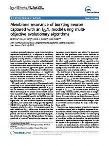
Section 2.4. Differences in measurements of velocities of master and slave inertial sensors constitute in north and east directions the measurement equation of the KF as discussed in Section 3.1, which provides opti� mal estimate for the misalignment. The use of time varying system transition matrix that feeds parameters like velocity, acceleration etc. from master INS data reduces computational needs but makes the stability analysis of the regulator a diffi� cult exercise to conduct. Experience suggests that the regulator coefficients have to be properly tuned by adjusting the state penalties in order to track the mis� alignment angles to zero even when the misalignment is correctly estimated by the filter. Figure 3 shows a typical run of an in�flight TA based on software simu� lation. From the figure, it is apparent that the veloci� ties of mother and daughter along north, west and ver� tical directions have matched and the filter has been able to estimate the misalignment angles closely (1 deg, 1 deg and 3 deg were used) while the regulated misalignment angles were tracked down to zero within 25–30 iterations.
139
0.30 0.25 0.20 0.15 0.10 0.05 0 –0.05 –0.10 –0.15
North West Vertical
0
20 40 60 80 10 30 50 70
Fig. 3. Tracking of misalignment angles and matching of velocities.
force sensed by the accelerometers in navigation frame, ∇c is the accelerometer drift error vector in c c local level frame, Δg is the gravity error vector, Ω ie is the skew symmetric matrix of angular rate between inertial frame and earth frame resolved in local level frame, ψ = [ψx ψy ψz] are the angles between the nav� igation frame and the local level frame, e p is the gyro� scope error vector in navigation frame [110]. The model described above has similarity with linear for� mulation, and can be used in situation where mis� alignment between the master and slave is not large enough. Some other formulation of TA problem for large misalignment angle may be found in [23, 114, 115]. Non�linear formulation of TA problem entails the use of some variants of CKF and may be found in [111, 116–118]. Extended Kalman Filter EKF provides an approximation of the optimal estimates of the system states, not the optimal esti� mate. For nonlinear systems (system and measure� ments being nonlinear), EKF uses local linearization techniques to provide approximate estimates of the system states. Probability based description of EKF may be found in [119]. In [107, 120], authors have described the use of EKF with the nonlinear formula� tion of TA problem, and have established the usability of such filter in TA problem. In [110], authors have shown that a large misalignment angle [–180°… +180°] may be approximated with a high degree of
2013
140
CHATTARA J et al.
accuracy [0.05°] within 15 seconds. A new method augmenting east gyro measurement in the measure� ment model and using EKF for estimation purpose have been proposed in [118], and improvement in per� formance in terms of convergence time of the filter is shown. Although EKF has been used extensively with nonlinear system models, it has some serious limita� tions to be considered. Performance of EKF is highly dependent on the accuracy of initialization of filter parameters. EKF is sure to produce wrong result if not initialized properly. Some implementations of EKF retain some higher order terms of the Taylor series expansion of the non�linear functions of the sys� tem and measurement model to increase the accuracy of the performance of the filter. Such retention of higher order terms increases the complexity of the algorithm both in terms of time and space, and thus is not often encouraged. Like CKF, EKF also assumes the noise model to be Gaussian, which may produce wrong approximation for the system states for systems perturbed by non Gaussian noise. As EKF uses approximated estimate of system states at each itera� tion, erroneous approximation may get propagated all along and thus convergence of EKF is not guaranteed unlike CKF. So, other variants need to be explored. Unscented Kalman Filter The use of UKF for estimation of states of a non� linear system was first proposed by Uhlmann and was modified by Julier in 1997. Detailed description of UKF along with equations governing the process may be found in [121] and [122]. UKF uses the principle of unscented transformation, which is essentially the method of finding the statistics of a random variable undergoing nonlinear transformation [121]. In UKF, the distribution of system states is specified by using a minimal set of sample points, known as sigma points. These sample points capture the mean and covariance of the system states and provide optimal estimate of posterior mean and variance when propa� gated through the true nonlinear model [122]. Beauty of UKF lies in the ability to work perfectly with any nonlinear system and the computational complexity is the same as EKF. Application of UKF in TA problem has started recently, around the year 2000 and some good work has been reported, although the topic is not vastly explored. In [123], a quaternion based attitude and sensor error model has been derived and application of an unscented filter has been reported. The authors proved that such an unscented filter works better when the sampling interval (interval between availability of two measurements from inertial sensors) is larger than the sampling interval used with EKF. In another work, [115], UKF is designed and tested for in� motion TA used with low cost inertial sensors. The capability of the filter to work with both large as well
as small misalignment angles has been demonstrated. The authors have described the use of unscented fil� tering for attitude estimation problem in [124]. A quaternion based nonlinear model for TA problem has been presented and use of UKF for filtering is demonstrated in [83]. In the same work, the designed filter is compared with RAP filter showing that the UKF performs as fast as a RAP if the misalignment is small. It was also shown that the designed filter per� forms well with large misalignment where RAP will fail to converge. Comparison is also made with a sim� ple velocity matching TA algorithm showing that con� vergence of proposed UKF based algorithm is faster than velocity matching TA algorithm. UKF has a number of advantages over EKF and its convergence is also guaranteed for almost all types of non�linear systems, but it has some limitations also. Like EKF, UKF assumes the system and mea� surement noise model to be Gaussian and requires the measurement model to be linear for optimal perfor� mance. Solution of these limitations of using UKF in TA problem leads one to resort to more powerful technique popularly known as a particle filter. Particle Filter PF tries to estimate the states of a system with the help of randomly generated samples called particles and associated weights by following Monte Carlo sim� ulation technique. For detailed description of PF technique see [119, 125, 126]. Application of PF in TA problem is advantageous because of the ability of the filter to perform satisfac� torily in systems with large misalignment and the use has been explored in number of works. In [111, 127– 129], authors have demonstrated the use of PF algo� rithm in TA problem and have shown that PF per� forms better than EKF and UKF in some situations. The nonlinear formulation of TA problem used in [107] has been used. Superiority of PF algorithm has been established through a comparison with EKF applied to the same problem. In a similar type of work, an optimal particle filter has been designed and the performance is compared with that of the EKF to prove the superiority of PF in [100]. A comparison also has been made between Gaussian PF (GPF) and UKF, and the performance of GPF has been shown to be better, in a work [82]. GPF approximates the pos� terior distribution of the system states by single Gaus� sian as is done in other Gaussian filters like EKF or its variants. This feature of GPF removes the require� ment to use resampling method which is mandatory in case of PF, as Gaussian approximation is not done in PF. Removal of resampling method from PF algo� rithm has significant advantages. It reduces the com� putational overhead to a great extent and allows fully parallel implementation of GPF algorithm [130]. In [82], authors have shown that the use of GPF in TA problem results in quicker convergence of misalign�
GYROSCOPY AND NAVIGATION
Vol. 4
No. 3
2013
TRANSFER ALIGNMENT PROBLEM: ALGORITHMS AND DESIGN ISSUES
ment angles to their expected values and also it works well with large misalignment case, while UKF gets influenced by such huge non�linearity. In [128], an improved PF algorithm called deterministic PF (DPF) has been proposed and the performance has been evaluated with respect to EKF. DPF has been shown to perform better than EKF for large misalign� ment angles. In the same work, authors have pro� posed a linear, non�linear hybrid model for the quaternion error dynamics. In [60], a comparison between the performance of two filtering approaches, Gaussian Approximation (GA) approach and Monte Carlo simulation (MCS) approach for TA problem has been done. Basically, when the performances of EKF, UKF and PF in TA problem are compared, PF performs better than other two filters in terms of time of convergence and accuracy for large misalignment angles. Major demerit of PF is the space and time complexity associated with practical implementation for TA problem. Other forms of nonlinear estimation algorithm like robust filter, etc., are also getting applied to TA prob� lem. For description of such a non�linear filter and applicability in in�ship TA problem see [58, 131, 132]. However, implementation of nonlinear filter has high computational complexity, and in a work [133], authors have shown that similar result may be found by using CKF of reduced computational burden. The performance of non�linear filtering in TA problem is a newer concept and its real time applicability is still a topic of further research. CONCLUSIONS While designing a TA algorithm, the following issues should be considered: 1. Nature of the launcher and the launched—this is the first thing to check for. Not all the variants of TA algorithm run successfully with all types of the launcher. For example, in�flight velocity matching TA algorithm usually requires a large manoeuvre, which cannot be performed with ship, and thus, attitude matching TA algorithm performs better than velocity matching for in�ship TA. 2. Check for available resources—the algorithms need to be altered according to the availability of resources. INS used in both the master and the slave are commercially off the shelf (COTS) resources. Its data rates, noise characteristics must be carefully studied and incorporated in the algorithm. Some� times, in such COTS devices, bias compensation is already done, and such issues must be considered. Data transfer rate of the mother and daughter may vary, and this may cause delay of measurement update in TA algorithm. It is the duty of the TA algorithm designer to modify their algorithms according to the resources available in hand. 3. Support of external aiding, especially GPS data, is very much helpful if used carefully. GPS support GYROSCOPY AND NAVIGATION
Vol. 4
No. 3
141
together with INS measurements can improve the level of accuracy of TA algorithm to a great extent. Unlike INS measurements, the nature of GPS data is transient, i.e., availability of GPS data may not be continuous and may be interrupted due to bad weather or some other factor. Thus, during a short duration of TA phase, only a few number of updates may be available from GPS. Care should be taken to handle this transient nature of availability of GPS measurements. GPS is often not mounted in daugh� ter due to optimization related issues, and thus, algo� rithms should be capable of continuing with INS mea� surements only when GPS data is not available. 4. Decide the launcher manoeuvre—preplanned manoeuvre is a must in some TA process, for exam� ple, inflight velocity matching TA algorithm. Either the knowledge of the manoeuvre is used to propagate the state transition matrix, or to update time varying values supplied from master data. The designer of TA algorithm needs to define the perfect manoeuvre for the optimal performance of the designed algorithm. While deciding the manoeuvre, it is required to con� sider some factors. For example, the point of ejection of the daughter is mostly dependent on the range of the seeker used with it, and TA needs to be finished prior to ejection. However, such a requirement is not encouraged when faster convergence of TA is of pri� mary interest and application of rapid transfer align� ment without the requirement of preplanned manoeuvre may be tested. 5. Determine system dynamics and type of filter— It is up to the designer whether to use a linear or a nonlinear formulation of TA problem with the design of the filter. Parameters like velocity, accelerations, etc., play key role in the propagation of the misalign� ment angle, and thus, need to be incorporated in sys� tem dynamics. Nature of real time noise is non�deter� ministic and no prior assumption regarding noise affecting a real time system is appropriate. On the other hand, noise statistics plays a key role in deter� mining the type of filter to be used in the TA process. Simple white Gaussian noise with normal probability distribution is used with linear system model and is applicable with CKF. EKF or its variant and UKF may be designed with non�linear system perturbed by white Gaussian noise. For more realistic implemen� tation, non Gaussian noise model may be chosen. CKF, EKF or even UKF will not work in such case, and one needs to choose a PF or some other variant of it. However, all types of filters have some merits as well as demerits for real time implementation which need to be considered while deciding the particular filter to be used. ACKNOWLEDGMENTS The authors acknowledge all project personnel attached with the work on TA at BESU, Shibpur and
2013
142
CHATTARA J et al.
the entire team of scientists working on TA at RCI, Hyderabad. REFERENCES 1. Spalding, K., An Efficient Rapid Transfer Alignment Filter, AIAA Guidance, Navigation and Control Confer� ence, 1992, pp. 1276–1286. 2. Parvin, R.H., Inertial Navigation Systems: Prelaunch Alignment, Aerospace and Navigational Electronics, IRE Transactions on, September 1962, vol. 9. no. 3, pp. 141–145. 3. Jurenka, F.D. and Leondes, C.T., Optimum Align� ment of An Inertial Autonavigator, Aerospace and Electronic Systems, IEEE Transactions on, November 1967, vol. 3, no. 6, pp. 880–888. 4. Hung, J.C. and White, H.V., Self�Alignment Tech� niques for Inertial Measurement Units, Aerospace and Electronic Systems, IEEE Transactions on, November 1975, vol. 11, no. 6, pp. 1232–1247. 5. Kalman, R.E., A New Approach to Linear Fitering and Prediction Problems, Journal of Basic Engineer� ing, 1960, vol. 82, 1960, pp. 35–42. 6. Deyst, J.J., Jr. and Sutherland, A.A., Jr., Strapdown Inertial System Alignment Using Statistical Filters � A Simplified Formulation, AIAA Journal, 1973, vol. 11, no. 4, pp. 452–456. 7. Bar Itzhack, I.Y. and Mallove, E.F., Accurate INS Transfer Alignment Using A Monitor Gyro and Exter� nal Navigation Measurements, Aerospace and Elec� tronic Systems, IEEE Transactions on, 1980, vol. 16, no. 1, pp. 53–65. 8. Kailath, T., An Innovations Approach to Least� Squares Estimation–Part I: Linear Filtering in Addi� tive White Noise, IEEE Transactions on Automatic Control, 1968, vol. 13, no. 6, pp. 646–655. 9. Kailath, T. and Frost, P., An Innovations Approach to Least�Squares Estimation–Part II: Linear Smoothing in Additive White Noise, IEEE Transactions on Auto� matic Control, 1968, vol. 13, no. 6, pp. 655–660. 10. Sorenson, H.W., Least�Squares Estimation: from Gauss to Kalman, Spectrum, IEEE, 1970, vol. 7, no. 7, pp. 63–68. 11. Eubank, R.L. and Wang, S., The Equivalence between the Cholesky Decomposition and the Kalman Filter, The American Statistician, 2002, vol. 56, no. 1, pp. 39–43. 12. Meinhold, R.J. and Singpurwalla, N.D., Understand� ing the Kalman Filter, The American Statistician, 1983, vol. 37, no. 2, pp. 123–127. 13. Grewal, M.S. and Andrews, A.P., Applications of Kal� man Filtering in Aerospace 1960 to the Present [His� torical Perspectives], IEEE Control and Systems Maga� zine, 2010, vol. 30, no. 3, pp. 69–78. 14. Chaudhuri, S.K. and Nandi, P.K., Transfer Alignment for Space Vehicles Launched from a Moving Base, Defence Science Journal, 2005, vol. 55, no. 3. 15. Simon, D., Kalman Filtering with State Constraints: A Survey of Linear and Nonlinear Algorithms, IET Con� trol Theory and Applications, 2010, vol. 4, no. 8, pp. 1303–1318.
16. Ding, G., Li, J., Zhou, W., and Cui, G., Study on Iter� ated Divided Difference Filtering and Its Application on TA Process with Large Initial Misalignment Angle, Information and Computing Science, International Con� ference on, 2010, vol. 1, pp. 243–247. 17. Ding, G., An, X., Zhou, W., and Cui, G., A New Numerical Approximation CDD Method Based for Particle Filtering Algorithm Research and Its Applica� tions to TA System, Measuring Technology and Mecha� tronics Automation (ICMTMA), 2011 Third Interna� tional Conference on, 2011, vol. 1, pp. 178–182. 18. Savage, P.S., Strapdown Inertial Navigation Integra� tion Algorithm Design– Part 1: Attitude Algorithms, Journal of Guidance, Control and Dynamics, 1998, vol. 21, no. 1, pp. 19–28. 19. Titterton, D.H. and Weston, J.L., Strapdown Inertial Navigation Technology, AIAA Education Series 17, Peter Peregrinus Ltd., 2004. 20. Lefferts, E.J., Markley, F.L., and Shuster, M.D., Kal� man Filtering for Spacecraft Attitude Estimation, AIAA 20th Aerospace Sciences Meeting, 1982, vol. 5, no. 5, pp. 417–429. 21. Groves, P.D., Optimising the Transfer Alignment of Weapon INS, Journal of Navigation, 2003, vol. 56, no. 2, pp. 323–335. 22. Ali, J. and Jiancheng, F., Alignment of Strapdown Inertial Navigation System: A Literature Survey Spanned over the Last 14 Years, Science, 2004, 100083: pp. 1–12. 23. Scherzinger, B.M., Inertial Navigator Error Models for Large Heading Uncertainty, Position, Location and Navigation Symposium, 1996, IEEE 1996, April 1996, pp. 477–484. 24. Jiang, Y.F. and Lin, Y.L., Error Estimation of INS Ground Alignment through Observability Analysis, Aerospace and Electronic Systems, IEEE Transactions on, January 1992, vol. 28, no. 1, pp. 92–97. 25. Sabatini, A.M., Quaternion Based Attitude Estima� tion Algorithm Applied to Signals from Body� Mounted Gyroscopes, Electronics Letters, May 2004, vol. 40, no. 10, pp. 584–586. 26. Savage, P.G., Strapdown System Computational Ele� ments, in Advances in Navigation Sensors and Integra� tion Technology, NATO RTO Lecture Series No. 232, October 2003. 27. Bortz, J.E., A New Mathematical Formulation for Strapdown Inertial Navigation, Aerospace and Elec� tronic Systems, IEEE Transactions on, January 1971, vol. 7, no. 1, pp. 61–66. 28. Carta, D. and Lackowski, D., Estimation of Orthogo� nal Transformations in Strapdown Inertial Systems, Automatic Control, IEEE Transactions on, February 1972, vol. 17, no. 1, pp. 97–100. 29. Baziw, J. and Leondes, C.T., In�Flight Alignment and Calibration of Inertial Measurement Units � Part I: General Formulation, Aerospace and Electronic Sys� tems, IEEE Transactions on, July 1972, vol. 8, no. 4, pp. 439–449. 30. Benson, D.O., A Comparison of Two Approaches to Pure�Inertial and Doppler�Inertial Error Analysis, Aerospace and Electronic Systems, IEEE Transactions on, July 1975, vol. 11, no. 4, pp. 447–455.
GYROSCOPY AND NAVIGATION
Vol. 4
No. 3
2013
TRANSFER ALIGNMENT PROBLEM: ALGORITHMS AND DESIGN ISSUES 31. Kain, J.E. and Cloutier, J.R., Rapid Transfer Align� ment for Tactical Weapon Applications, Proceedings of AIAA Guidance, Navigation and Control Conference, 1989. 32. Grewal, M.S., Henderson, V.D., and Miyasako, R.S., Application of Kalman Filtering to the Calibration and Alignment of Inertial Navigation Systems, Automatic Control, IEEE Transactions on, January 1991, vol. 36, no. 1, pp. 3–13. 33. Nash, R.A., Levine, S.A., and Roy, K.J., Error Analy� sis of Space�Stable Inertial Navigation Systems, Aero� space and Electronic Systems, IEEE Transactions on, July 1971, vol. 7, no. 4, pp. 617–629. 34. Crassidis, J.L., Space, G., and Markley, F.L., A Mini� mum Model Error Approach for Attitude Estimation, Journal of Guidance Control and Dynamics, 1995, vol. 20, no. 6, pp. 1241–1247. 35. Gelb. A., Synthesis of a Very Accurate Inertial Naviga� tion System, Aerospace and Navigational Electronics, IEEE Transactions on, June 1965, vol. 12, no. 2, pp. 119–128. 36. Hutchinson, C.E. and Nash, R.A., Comparison of Error Propagation in Local�Level and Space�Stable Inertial Systems, Aerospace and Electronic Systems, IEEE Transactions on, November 1971, vol. 7, no. 6, pp. 1138–1142. 37. Hodson, A.E., Optimal Levelling and Gyrocompass� ing of Inertial Systems, IEEE Transactions on Aero� space and Navigational Electronics, 1963, vol. ANE� 10, no. 1, pp. 18–26. 38. Bar�Itzhack, I.Y. and Berman, N., Control Theoretic Approach to Inertial Navigation Systems, Journal of Guidance, Control, and Dynamics, June 1988, vol. 2, pp. 1442–1453. 39. Fang, J.Ch. and Wan, D.J., A Fast Initial Alignment Method for Strapdown Inertial Navigation System on Stationary Base, Aerospace and Electronic Systems, IEEE Transactions on, October 1996, vol. 32, no. 4, pp. 1501–1504. 40. Cao, S. and Guo, L., Multi�Objective Robust Initial Alignment Algorithm for Inertial Navigation System with Multiple Disturbances, Aerospace Science and Technology, 2012, vol. 21, no. 1, pp. 1–6. 41. Jones, D., Roberts, C., Tarrant, D., Yang, Ch., and Lin, Ch.�F., Transfer Alignment Design and Evalua� tion Environment, Proceedings of the First IEEE Regional Conference on Aerospace Control Systems, 1993, pp. 753–757. 42. Dissanayake, G., Sukkarieh, S., Nebot, S., and Whyte, H.D., A New Algorithm for the Alignment of Inertial Measurement Units without External Obser� vation for Land Vehicle Applications, Proceedings of IEEE International Conference on Robotics and Auto� mation, 1999, vol. 3, pp. 2274–2279. 43. Salzwedel, H.C. and Kesseler, K.M., Transfer of Alignment and Calibration of Multiple Sensors in Flexible Systems, 24th IEEE Conference on Decision and Control, 1985, vol. 24, pp. 1932–1937. 44. Stimac, L.W. and Kennedy, T.A., Sensor Alignment Kalman Filters for Inertial Stabilization Systems, Position Location and Navigation Symposium, 1992, 500 Years after Columbus � Navigation Challenges of GYROSCOPY AND NAVIGATION
Vol. 4
No. 3
2013
143
Tomorrow. IEEE PLANS '92, IEEE, March 1992, pp. 321–334. 45. Shuster, M.D., A Simple Kalman Filter and Smoother for Spacecraft Attitude, Journal of the Astronautical Sciences, 1989, vol. 37, no. 1, pp. 89–106. 46. Gao, Q., Zhao, Q., and Wang, X., The Model and Simulation of Transfer Alignment of Carrier Based Aircraft INS with Large Azimuth Misalign Angle, International Joint Conference on Computational Sci� ences and Optimization, 2009, vol. 1, pp. 355–358. 47. Silson, P.M.G., Coarse Alignment of a Ship’s Strap� down Inertial Attitude Reference System Using Veloc� ity Loci, Instrumentation and Measurement, IEEE Transactions on, 2011, vol. 60, no. 6, pp. 1930–1941. 48. Majeed, S. and Fang, J., Performance Improvement of Angular Rate Matching Shipboard Transfer Align� ment, 9th International Conference on Electronic Mea� surement Instruments, 2009, pp. 706–711. 49. Xiaorong, Sh. and Yongzhu, Sh., Angular Rate Matching Method for Shipboard Transfer Alignment Based on H Infinity Filter, 6th IEEE Conference on Industrial Electronics and Applications (ICIEA), June 2011, pp. 620–625. 50. Ross, C.C. and Elbert, T.F., A Transfer Alignment Algorithm Study Based on Actual Flight Test Data from a Tactical Air to Ground Weapon Launch, Pro� ceedings of 1994 IEEE Position Location and Naviga� tion Symposium PLANS94, pp. 431–438. 51. Gao, W., Ben, Y., Sun, F., and Xu, B., Performance Comparison of Two Filtering Approaches for INS Rapid Transfer Alignment, International Conference on Mechatronics and Automation, 2007, ICMA 2007, pp. 1956–1961. 52. Schlee, F.H., Toda, N.F., Islam, M.A., and Standish, C.J., Use of an External Cascade Kalman Filter to Improve the Performance of a Global Posi� tioning System (GPS) Inertial Navigator, Proceedings of Aerospace and Electronics Conference, 1988, NAE� CON 1988., vol. 1, pp. 345–350. 53. Groves, P.D., Transfer Alignment Using an Integrated INS/GPS as the Reference, Journal of Navigation, 1999, pp. 731–737. 54. Gao, Q., Zhao, G., and Wang, X., Transfer Alignment Error Compensator Design for Flexure and Lever Arm Effect, 4th IEEE Conference on Industrial Electronics and Applications, 2009, pp. 1819–1822. 55. Joon, L. and You�Chol, L., Transfer Alignment Con� sidering Measurement Time Delay and Ship Body Flexure, Journal of Mechanical Science and Technol� ogy, 2009, vol. 23, pp. 195–203, 10.1007/s12206�008� 0821�y. 56. Nie, Q., Gao, X., Li, Z., Li, Y., and Jiao, Ch., The Error Compensation Design for Transfer Alignment, International Conference on Mechatronics and Automa� tion, 2010, pp. 1886–1891. 57. Changyue, S. and Zhenglong, D., Transfer Alignment of Shipborne Inertial�Guided Weapon Systems, Jour� nal of Systems Engineering and Electronics, April 2009, vol. 20, no. 2, pp. 348–353. 58. Lyou, J. and Lim, Y.�Ch., Transfer Alignment Error Compensator Design Based on Robust State Estima� tion, Transactions of the Japan Society for Aeronautical
144
CHATTARA J et al.
and Space Sciences, 2005, vol. 48, no. 161, pp. 143– 151. 59. Cheng, L., Zhi�Hong, D., Wen�Shao, G., and Meng� Yin, Fu, Estimate Dynamic Lever�Arm Caused by Ship Flexure Deformation Based on Acceleration Matching, Chinese Control Conference, 2011, pp. 1476–1481. 60. Nai�Xin, Zh., Si, W., and Zheng�Long, W., Compari� son of Three Transfer Alignment Methods in Marine Missile SINS, Chinese Control Conference, 2006, pp. 27–31. 61. Lim, Y.�Ch. and Lyou, J., An Error Compensation Method for Transfer Alignment, Proceedings of IEEE Region 10 International Conference on Electrical and Electronic Technology TENCON, 2001, vol. 2, pp. 850– 855. 62. Zhihua, F., Weiwei, J., and Shesheng, G, Research of Rapid Transfer Alignment and Observability Analysis, 2nd International Conference on Intelligent Control and Information Processing (ICICIP), 2011, vol. 1, pp. 204–207. 63. Sun, F., Wang, G., Ben, Y.Y, and Chai, Y.L, The River Trials for The Velocity Matching and Velocity Plus Attitude Matching Transfer Alignments, International Conference on Mechatronics and Automation, ICMA, 2009, pp. 4156–4161. 64. Chen, K., Zhao, G., Meng, Zh., Yan, J., and Lu, H., Equivalent Approaches to Equations of Traditional Transfer Alignment and Rapid Transfer Alignment, 7th World Congress on Intelligent Control and Automation, 2008, pp. 892–895. 65. Meldrum, D.T. and Haddrell, T., GPS in Autonomous Underwater Vehicles, IEE Conference Publications, 1994(CP394), pp. 11–17. 66. Sutherland, A.A., Jr., The Kalman Filter in Transfer Alignment of Inertial Guidance Systems, Journal of Spacecraft and Rockets, 1968, vol. 5, pp. 1175–1180. 67. Johnson, C., In�Flight Transfer Alignment/Calibra� tion of a Strapdown INS That Employs Carouseled Instruments and IMU Indexing, American Control Conference, 1986, pp. 1572–1573. 68. Guoqiang, D., Weidong, Zh., Yanling, H., and Feng, S., The Impact of Arm�Lever Effect Error Based Large Initial Misalignment Transfer Alignment Tech� nology Study, International Workshop on Intelligent Systems and Applications, 2009, pp. 1–6. 69. Zhou, W., Ding, G., Hao, Y., and Cui, G., Research on the Effect of Ship’s Deck Deflection on Angular Rate Matching Based Transfer Alignment Process, International Conference on Mechatronics and Automa� tion, 2009, pp. 3218–3222. 70. Weston, J.L. and Titterton, D.H., Modern Inertial Navigation Technology and Its Application, Electron� ics Communication Engineering Journal, April 2000, vol. 12, no. 2, pp. 49–64. 71. Barbour, N. and Schmidt, G., Inertial Sensor Tech� nology Trends, Sensors Journal, IEEE, 2001, vol. 1, no. 4, pp. 332–339. 72. Ragan, R.R. et al., Inertial Technology for the Future, IEEE Transactions on Aerospace and Electronic Sys� tems, July 1984, vol. 20, no. 4, pp. 414–444.
73. King, A.D. and Marconi Electronics Systems, Inertial Navigation. Forty Years of Evolution, GEC Review, 1998, vol. 13, no. 3, pp. 140–149. 74. Barbour, N.M., Inertial Navigation Sensors, Technol� ogy, 2010, no. 116, pp. 1–24. 75. Culshaw, B., Fiber Optics in Sensing and Measurement, 2000. 76. Savage, P.G. and Strapdown Associates Inc Min� netonka MN, Advances in Strapdown Sensors, 1984. 77. Barbour, N.M., Elwell, J.M., and Setterlund, R.H., Inertial instruments: Where to now? The Charles Stark Draper Laboratory Inc, Cambridge Massachusetts 02139, 1992, p. 9. 78. El�Sheimy, N. and Niu, X., The Promise of MEMS to the Navigation Community, Inside GNSS, March� April 2007, pp. 46–56. 79. Lefevre, H.C., The Fiber�Optic Gyroscope: Achieve� ment and Perspective, Gyroscopy and Navigation, 2012, vol. 3, no. 4, pp. 223–226. 80. Geng, Y., Deurloo, R., and Bastos, L., Hybrid Deriv� ative�Free Extended Kalman Filter for Unknown Lever Arm Estimation in Tightly Coupled DGPS/INS Integration, GPS Solutions, 2011, no. 15, pp. 181–191. 81. Guo, L.and Cao, S., Robust Initial Alignment for Inertial Navigation Systems with Multiple Types of Disturbances, International Symposium on Advanced Control of Industrial Processes (ADCONIP), 2011, pp. 369–373. 82. Hao, Y., Xiong, Zh., and Hu, Z., Particle Filter for INS In�Motion Alignment, The 1st IEEE Conference on Industrial Electronics and Applications, 2006, pp. 1–6. 83. Hao, Y., Xiong, Zh., Wang, W., and Sun, F., Rapid Transfer Alignment Based on Unscented Kalman Fil� ter, American Control Conference, 2006, p. 6. 84. Hao, Y., Xiong, Zh., and Xiong, B., Estimation Error of INS Transfer Alignment through Observability Analysis, 1st International Symposium on Systems and Control in Aerospace and Astronautics, 2006, p. 558. 85. Emelyantsev, G.I., Dranitsyna, E.V., and Blazhnov, B.A., Test Bed Calibration of FOG�Based Strapdown Inertial Measurement Unit, Gyroscopy and Navigation, 2012, vol. 3, no. 4, pp. 265–269. 86. Shortelle, K.J., Graham, W.R., and Rabourn, C., F� 16 Flight Tests of a Rapid Transfer Alignment Proce� dure, Position, Location and Navigation Symposium, IEEE 1998, pp. 379–386. 87. Tarrant, D, Roberts, C., Jones, D., Yang, Ch., and Lin, Ch.�F., Rapid and Robust Transfer Alignment, Proceedings of the First IEEE Regional Conference on Aerospace Control Systems, 1993, pp. 758–762. 88. Groves, P., Wilson, G.G., and Mather, C.J., Robust Rapid Transfer Alignment with an INS/GPS Refer� ence, Simulation, July 2002, pp. 301–311. 89. Hongzhong, L. and Yuliang, M., Study on a Method of Rapid Transfer Alignment, International Conference on Mechatronic Science, Electric Engineering and Com� puter (MEC), 2011, pp. 1423–1426. 90. Zhou, Sh., Xu, H., Dai, H., and Wu, G., Novel Rapid Transfer Alignment Algorithm for Strapdown Inertial Navigation System, International Conference on Elec�
GYROSCOPY AND NAVIGATION
Vol. 4
No. 3
2013
TRANSFER ALIGNMENT PROBLEM: ALGORITHMS AND DESIGN ISSUES trical and Control Engineering (ICECE), 2011, pp. 6012–6016, 2011. 91. Ya�Feng, W., Fu�Chun, S., and Youan, Zh, A Method for Rapid Transfer Alignment Based on UKF, IMACS Multiconference on Computational Engineering in Sys� tems Applications, 2006, vol. 1, pp. 809–813. 92. Xiong, Zh., Sun, F., and Nie, Q., Observability Analy� sis of INS Rapid Transfer Alignment, The Sixth World Congress on Intelligent Control and Automation, WCICA, 2006, vol. 1, pp. 1664–1668. 93. Xiong, Sh., Guo, L., Feng, G., Qu, Y., and Sun, F., Take�off Alignment Algorithm of Carrier Aircraft INS, 2nd IEEE Conference on Industrial Electronics and Applications, ICIEA, 2007, pp. 2333–2339. 94. Rogers, R.M., Weapon IMU Transfer Alignment Using Aircraft Position from Actual Flight Tests, Posi� tion, Location and Navigation Symposium, 1996., IEEE 1996, pp. 328–335. 95. Rogers, R.M., Low Dynamic IMU Alignment, Posi� tion, Location and Navigation Symposium, IEEE 1998, pp. 272–279. 96. Baziw, J. and Leondes, C.T., In�Flight Alignment and Calibration of Inertial Measurement Units � Part II: Experimental results, IEEE Transactions on Aerospace and Electronic Systems, 1972, vol. 8, no. 4, pp. 450– 465. 97. Hagan, C.E. and Lofts, C.S., Accelerometer Based Alignment Transfer (ABAT), Position, Location and Navigation Symposium, 1992, 500 Years After Columbus � Navigation Challenges of Tomorrow, IEEE PLANS '92, IEEE, pp. 133–140. 98. Hagan, C.E. and Lofts, C.S., Gravity Observation Based Alignment Transfer, Proceedings of the First IEEE Regional Conference on Aerospace Control Sys� tems, 1993, pp. 763–767. 99. Ali, J. and Fang, J., SINS/ANS Integration for Aug� mented Performance Navigation Solution Using Unscented Kalman Filtering, Aerospace Science and Technology, 2006, vol. 10, no. 3, pp. 233–238. 100. Carvalho, H., Del Moral, P, Monin, A., and Salut, G., Optimal Nonlinear Filtering in GPS/INS integration, IEEE Transactions on Aerospace and Electronic Sys� tems, 1997, vol. 33, no. 3, pp. 835–850. 101. Crassidis, J.L., Sigma�Point Kalman Filtering for Inte� grated GPS and Inertial Navigation, 2006. 102. Mohamed, A.K. and Schwarz, K.P., Adaptive Kalman Filtering for INS/GPS, Journal of Geodesy, 1999, vol. 73, pp. 193–203. 103. Hide, C., Moore, T., and Smith, M., Adaptive Kalman Filtering Algorithms for Integrating GPS and Low Cost INS, Position Location and Navigation Sympo� sium PLANS 2004, 2004, pp. 227–233. 104. Qi, H. and Moore, J.B., Direct Kalman Filtering Approach for GPS/INS Integration, 2002. 105. Klotz, H.A. and Derbak, C.B., GPS�Aided Naviga� tion and Unaided Navigation on the Joint Direct Attack Munition, Position Location and Navigation Symposium, IEEE 1998, 1998, pp. 412–419. 106. Åkesson, B.M., Jorgensen, B., and Poulsen, K., A Tool for Kalman Filter Tuning, 17th European Sympo� sium on Computer Aided Process Engineering, 2007, vol. 24, pp. 859–864. GYROSCOPY AND NAVIGATION
Vol. 4
No. 3
145
107. Dmitriyev, S.P., Stepanov, O.A., and Shepel, S.V., Nonlinear Filtering Methods Application in INS Alignment, Aerospace and Electronic Systems, IEEE Transactions on, 1997, vol. 33, no. 1, pp. 260–272. 108. Shuster, M.D., Survey of Attitude Representations, Journal of the Astronautical Sciences, 1993, vol. 41, no. 4, pp. 439–517. 109. Crassidis, J.L., Markley, F., and Cheng, Y., Survey of Nonlinear Attitude Estimation Methods, Journal of Guidance, Control and Dynamics, 2007, vol. 30, no. 1, pp. 12–28. 110. Kong, X., Nebot, E.M., and Durrant�Whyte, H., Development of a Nonlinear Psi�Angle Model for Large Misalignment Errors and Its Application in INS Alignment and Calibration, IEEE International Con� ference on Robotics and Automation, 1999. vol. 2, pp. 1430–1435. 111. Zhao, R. and Gu, Q., Nonlinear Filtering Algorithm with Its Application in INS Alignment, Proceedings of the Tenth IEEE Workshop on Statistical Signal and Array Processing Cat No00TH8496, 2000, pp. 510– 513. 112. Hong, H.S., Lee, J.G., and Park, C.G., Performance Improvement of In�Flight Alignment for Autonomous Vehicle under Large Initial Heading Error, IEEE Pro� ceedings Radar, Sonar and Navigation, 2004, vol. 151, no. 1, pp. 1–6. 113. Scherzinger, B.M. and Reid, D.B., Modified Strap� down Inertial Navigator Error Models, IEEE Position, Location and Navigation Symposium, 1994, pp. 426– 430. 114. Pham, T.M., Kalman Filter Mechanization for INS Airstart, IEEE Aerospace Electronic Systems Magazine, 1992, vol. 7, no. 1, pp. 3–11. 115. Shin, E.�U. and El�Sheimy, N., An Unscented Kal� man Filter for In�Motion Alignment of Low�Cost IMUs, Position, Location and Navigation Symposium PLANS, 2004, pp. 273– 279. 116. Jiancheng, F. and Sheng, Y, Study on Innovation Adaptive EKF for In�Flight Alignment of Airborne POS, Instrumentation and Measurement, IEEE Trans� actions on, 2011, vol. 60, no. 4, pp. 1378–1388. 117. Kubo, Y. and Fujioka, S., Nonlinear Filtering Meth� ods for the INS/GPS In�Motion Alignment and Nav� igation, Information and Control, 2006, vol. 2, no. 5, pp. 1137–1151, 2006. 118. Acharya, A., Sadhu, S., and Ghoshal, T.K., Improved Self�Alignment Scheme for SINS Using Augmented Measurement, Aerospace Science and Technology, 2011, vol. 15, no. 2, pp. 125–128. 119. Arulampalam, M.S., Maskell, S, Gordon, N., and Clapp, T, A Tutorial on Particle Filters for Online Nonlinear/Non�Gaussian Bayesian Tracking, IEEE Transactions on Signal Processing, 2002, vol. 50, no. 2, pp. 174–188. 120. Mehra, R., Seereeram, S, Bayard, S., and Hadaegh, S., Adaptive Kalman Filtering, Failure Detection and Identification for Spacecraft Attitude Estimation, Pro� ceedings of the 4th IEEE Conference on Control Appica� tions, 1995, pp. 176–181. 121. Julier, S.J. and Uhlmann, J.K, A New Extension of the Kalman Filter to Nonlinear Systems, International
2013
146
CHATTARA J et al.
Symposium on Aerospace/Defense Sensing, Simulation and Controls, 1997, vol. 3, pp. 182–193. 122. Wan, E.A. and Van Der Merwe, R., The Unscented Kalman Filter for Nonlinear Estimation, Technology, 2000, vol. 3, pp. 153–158. 123. Kok�Lam Lai, Crassidis, J.L., and Harman, R.R., In� space Spacecraft Alignment Calibration using the Unscented Filter, Systems Engineering, August 2003. 124. Crassidis, J.L. and Markley, F.L., Unscented Filtering for Spacecraft Attitude Estimation, Systems Engineer� ing, 2003, vol. 26, no. 4, pp. 536–542. 125. Doucet, A., and Johansen, A.M., A Tutorial on Parti� cle Filtering and Smoothing: Fifteen Years Later, in Handbook of Nonlinear Filtering, 2008, pp. 4–6. 126. Maskell, S. and Gordon, N., A Tutorial on Particle Filters for On�Line Nonlinear/Non�Gaussian Baye� sian Tracking, IEE Seminar Digests, 2001, vol. 174:v2� 2�v2�2. 127. Cheng, Y. and Crassidis, Y.L., Particle Filtering for Sequential Spacecraft Attitude Estimation, Control, 2004, pp. 892–895. 128. Ding, G., Zhou, W., Hao, Y. and Cui, G., Determin� istic Particle Filter Based Transfer Alignment Method
for Large Misalignment Angle, International Confer� ence on Mechatronics and Automation, ICMA, 2009, pp. 3387–3392. 129. Wang, Y., Sun, F., Zhang, Y., Liu, H., and Min, H., Central Difference Particle Filter Applied to Transfer Alignment for SINS on Missiles, Aerospace and Elec� tronic Systems, IEEE Transactions on, 2012, vol. 48, no. 1, pp. 375–387. 130. Kotecha, J.H. and Djuric, P.M., Gaussian Particle Fil� tering, 2003. 131. Lim, Y.Ch. and Lyou, J., Transfer Alignment Error Compensator Design Using H�infinity Filter, Pro� ceedings of American Control Conference, 2002, vol. 2, pp. 1460–1465. 132. Fei, Y. and Feng, S., Application of H Filtering in the Initial Alignment of Strapdown Inertial Navigation System, Journal of Marine Science and Application, 2005, vol. 4, no. 1, pp. 50–53. 133. Li, J, Dai, H.�D., Wu, G.�B., and Sun, Y.�Y., Pseudo Measurement�Based Rapid Transfer Alignment, Chen, R., Ed., International Conference in Electrics, Communication and Automatic Control Proceedings, 2012, Springer New York, pp. 703–709.
GYROSCOPY AND NAVIGATION
Vol. 4
No. 3
2013