Two Compact Configurations for Implementing Transmission Zeros in Microstrip Filters David Cañete Rebenaque, F. Quesada Pereira, J. Pascual García, A. Alvarez Melcón, and M. Guglielmi
Abstract—This contribution presents compact structures for the implementation of transmission zeros using the zero shifting property. First, two open-loop resonators operating at different resonances are employed. Then, one of the open-loop resonators is substituted by a ( 4) short-circuited transmission line, thus resulting into a more compact structure. Properties of these configurations are discussed, and two manufactured prototypes have been sucessfully tested. The results show the usefullness and validity of the new structures with high rejection capabilities. Index Terms—Microstrip filters, poles and zeros, transmission zeros.
I. INTRODUCTION
T
HIS LETTER is focused on the development of new microwave filter structures for high selectivity applications. This type of design is of key importance for the radio frequency engineer, since they are currently used in communication applications to reject spurious signals, and to separate different channels in a multichannel communication system [1]. This need of rejecting certain unwanted frequencies led in the past to the development of filters whose insertion loss response exhibits transmission zeros at finite frequencies [2]. The method traditionally used for the implementation of transmission zeros is the introduction of cross couplings between nonadjacent resonators [3]. Recently, an alternative technique for the implementation of transmission zeros was proposed in [4]. Similar principles of operation are behind the implementation of transmission zeros in waveguide filters using inductive steps [5]. In this technique, the signal is coupled to several resonators, providing more than one main path for the signal between the input and output ports. When the phase difference for the signal in the two paths equals 180 , a cancellation of energy is produced, thus resulting in the sought for transmission zero. An important advantage of this method, is that transmission zeros can be easily shifted from one side of the passband to the other side. Following the basic principles of operation described in [4], two practical implementations of filters in microstrip technology are presented. The first structure is composed of two open-loop resonators coupled to the input and output lines.
work was supported by the Spanish National Projects ESP2001-4546-PE and TIC2000-0591-C03-03, and the Regional Seneca Project 2002, ref. PB/4/FS/02. D. C. Rebenaque, F. Q. Pereira, J. P. García, and A. A. Melcón are with the Technical University of Cartagena, Cartagena, Murcia E-30202, Spain (e-mail:
[email protected]). M. Guglielmi is with the European Space Agency (ESA/ESTEC), Noordwijk 2200 AG, The Netherlands. Digital Object Identifier 10.1109/LMWC.2004.834564
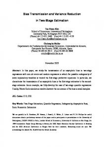
Fig. 1.
First filter configuration proposed.
These two resonators operate at an even and odd resonances respectively, producing the change in phase required to implement a transmission zero. In this context, we propose also an alternative configuration. This second structure is more compact, since the larger openloop resonator is substituted by a ( ) short-circuited transmission line. Also, the new structure has shown to be able to handle larger bandwidths than the first design. This is due to the possibility of implementing larger coupling coefficients between the input and output lines to the new short-circuited transmission line. For this purpose, a novel cross-shaped coupling structure is proposed. II. STRUCTURE DESCRIPTION The principle of operation of the novel planar structures, which are proposed in this letter, is to provide more than one main path to the signal from the input to the output ports. A first design is shown in Fig. 1. This idea was also proposed in [4] in the context of novel coupling schemes to achieve elliptic transfer functions, but no practical implementations were reported. It consists on the input and output lines which are coupled, in a shunted configuration, to two open-loop resonators of different lengths. One resonator is designed to work at a suitable odd resonance, while the other is designed to operate at the next even resonance. The interactions of the signal in both paths produce the required cancellation of energy at a given frequency. The two main geometrical parameters in this structure are the lengths of the resonators, whose approximated values to get the most compact design are and , respectively, at the center frequency of the passband. By fine adjusting these two lengths, the cancellation of energy, and therefore the transmission zero,
Fig. 2.
Second filter configuration proposed.
Fig. 4. Basic response for a filter shown in Fig. 3 with one transmission zero below (type I) and above (type II) the passband. The common dimensions of both type of filters are L = 10:35 mm, L = 9:15 mm, L = 21:80 mm, = 1 mm, L = L = 15:5 mm, w = 2:1 mm, s = 0:2 mm, and L s = 0:2 mm. Substrate Duroid RT/6006. Fig. 3.
Third filter configuration proposed.
occurs in the proximity of the center frequency, leading to a sharp transition between the transmission and the cut-off bands. The second configuration proposed consists on input and output lines coupled to both, an open-loop resonator in a shunted configuration, and to a short-circuited transmission line (see Fig. 2). The length of the open-loop resonator is approximately , while the length of the short-circuited line is set to . The loop resonator inverts the phase of the signal, so that a cancellation of energy is produced at the output line. For the practical implementation of this structure, the shortcircuited transmission line is modified to a novel cross-shaped configuration, as it can be seen in Fig. 3. This new structure is more compact, and has shown to be able to increase the input and output couplings, therefore being able to handle larger bandwidths than the previous design. An advantage of the proposed configurations is that transmission zeros can be easily placed using the zero shifting property [4]. This allows an easy design of asymmetric responses with improved selectivity below (response of type I in Fig. 4, with mm and mm), or above (response of type mm and mm) the passII in Fig. 4, with band, by just slightly varying the ratio between the lengths of both resonators. Bandwidth can be controlled in the usual way by acting on the input and output couplings. A smaller gap results in a stronger coupling, so wider bandwidth is achieved, as can be seen in Fig. 5. In these type of filters, the position of the transmission zero strongly affects the interresonator coupling between both resonators. Independent control of this interresonator coupling can be achieved by adjusting asymmetrically the and gaps of Fig. 3. Another advantage of this kind of structures, is that several units of the previously described type can be easily cascaded to
Fig. 5. Variation of the filter response with input/output couplings for the structure in Fig. 3. Data1: s = s = 0:1 mm, Data2: s = s = 0:2 mm, and Data3: s = s = 0:4 mm.
produce higher order responses. The inline configuration created with this approach, leads to a structure in which the different sections have little influence on the others [4]. As a consequence, each basic section can be optimized separately, and then connected to the final structure with little tuning or readjustment of the individual units. III. RESULTS For the simulation and optimization of the proposed structures, a full wave electromagnetic analysis tool, namely the HP-ADS software, was employed. A first prototype, using the concept depicted in Fig. 1, was manufactured in microstrip technology. The material for manufacturing is a Duroid RT/6006 and thickness mm). This filter substrate ( implements a tranmission zero below the bandpass, and has the
Fig. 6. Manufactured filter prototypes.
Fig. 8. Measured and simulated S -parameters for the filter on the right of Fig. 6. Dimensions according to Fig. 4.
COMPARISON OF Q
Fig. 7. Measured and simulated S -parameters for the filter on the left of Fig. 6. According to Fig. 1, the dimensions are L = L = 9:15 mm, L = 21 mm, =L = 8 mm, w = 2:1 mm, and L = 3:05 mm, L = 28:1 mm, L s = s = 0:3 mm.
layout shown on the left of Fig. 6. Chamfered corners are used in both resonators to minimize radiation (0.13 dB radiation losses within the passband are obtained). A second filter with a transmission zero above the passband was manufactured using the same substrate. In this case the filter was designed according to the configuration shown in Fig. 3. The final manufactured hardware can be seen on the right of Fig. 6. The short-circuit has been implemented with a via hole mm. of diameter In Figs. 7 and 8 the results are compared for the scattering parameters of the filter. In these figures the simulated data include losses in both, the dielectric substrate and in the metallic areas of the structure (finite conductivity). Very good agreement between measured and predicted results can be seen. The second transmission zero away from the passband is thought to be due to a parasitic coupling between the source and the load. It is worth mentioning that the size of the second structure is reduced by a 50% with respect to the first one. In addition, the attainable bandwidth varies from 1% to 3% for the two-open-loop resonator structure (Fig. 1), while for the third configuration (Fig. 3) the range of variation is from 4% to 9%. The external quality factor ( ) obtained for the three types of resonators described in the letter is shown in Table I. The ) stub resonator shows higher ( ) than the others, indi(
TABLE I DIFFERENT TYPES OF RESONATORS
FOR
cating poor capability to synthesize wide bandwidth responses. On the other hand, the cross-shaped stub has lower ( ) than the open-loop resonator, making it suitable for wide bandwidth applications. IV. CONCLUSION In this letter, we have presented novel microstrip filter structures exhibiting high selectivity. The transmission zero is implemented by providing different main paths to the signal from input to output ports, so that destructive interference can take place. Two filter prototypes have been designed, manufactured and tested, and their main properties and advantages have been carefully discussed. Measured results confirm the validity and usefulness of the proposed structures. REFERENCES [1] R. M. Kurzok, “General four-resonators filters at microwave frequencies,” IEEE Trans. Microwave Theory Tech, vol. MTT-14, pp. 295–296, July 1966. [2] C.-C. Chen, Y.-R. Chen, and C.-Y. Chang, “Miniaturized microstrip cross-coupled filters using quarter wave or quasi quarter wave resonators,” IEEE Trans. Microwave Theory Tech, vol. 51, pp. 120–131, Jan. 2003. [3] J. S. Hong and M. J. Lancaster, “Design of highly selective microstrip bandpass filters with a single pair of attenuation poles at finite frequencies,” IEEE Trans. Microwave Theory Tech, vol. 48, pp. 1098–1107, July 2000. [4] U. Rosenberg and S. Amari, “Novel coupling schemes for microwave resonator filters,” IEEE Trans. Microwave Theory Tech, vol. 50, pp. 2896–2902, Dec. 2002. [5] M. Guglielmi, P. Jarry, E. Kerherve, O. Roquebrun, and D. Schmitt, “A new family of all-inductive dual-mode filters,” IEEE Trans. Microwave Theory Tech, vol. 49, pp. 1764–1769, Oct. 2001.