10. Basic geometry modeling uses combinatorial geometry for ease of input and ..... 15*0 2*1 5*2 2*3 5*4 5*5 5*6 4*7 4*8 4*9 4*10 4*11 MARS card 6 : Universe ...
UCMARS - A User Code with a Multiple-Array System using Combinatorial Geometry for EGS4
- Linux version -
April 2001
Osamu Sato*, Shunji Takagi*, Satoshi Iwai* and Hideo Hirayama**
* Mitsubishi Research Institute Inc., 3-6 Ohtemachi 2-Chome, Chiyoda-ku, Tokyo, Japan 100-8141 ** National Laboratory for High Energy Physics, Oho, Tsukuba-shi, Ibaraki 305, Japan
Abstract - A user code for EGS4 was developed for modeling a complex geometry with repeated structure. The user code incorporates the MARS geometry package developed by ORNL. It allows the users to model many rectangular arrays containing a geometry modeled by a combinatorial geometry with unlimited array nesting. A sample user code is presented to describe how to use MARS package in the subroutine HOWFAR . INTRODUCTION Since the electromagnetic cascade code EGS4(1) requires users to make a user code for their own purpose, it therefore has flexibility for the specifications of geometry modeling, detectors, and other calculation conditions. The user code includes a subroutine representing a geometry for calculations, called HOWFAR. In HOWFAR, it must be calculated at a distance from the present point to the point at which the particle track will cross a boundary between different materials, although it is difficult to model a complex geometry, such as a combination of spheres, cylinders and rectangules, with a simple algorism. For modeling a complex geometry, combinatorial geometry (CG) package obtained from MORSE(2) Monte Carlo code have been used for EGS4, and a sample user code was shown as UCSAMPCG in SLAC-265(1). The combinatorial geometry allows a description of the physical structures by combining certain basic geometric shapes (bodies), such as rectangular parallelepipeds, right circular cylinders, and a Boolean combination of them. The MARS(3) geometry system has been developed to allow one to model the complex lattice geometry of CG efficiently and quickly with a minimum of geometric approximations and a minimum of computer memory requirements. By using MARS with EGS4, it allows one to simulate an electromagnetic cascade in a complex repeated structure, such as a realistic modeling of a calorie meter. MARS GEOMETRY SYSTEM Features of MARS MARS (Multiple Array System) is a geometry system based on combinatorial geometry (CG) package, which was developed by Oakridge National Laboratory (ORNL) for the SCALE(4) computer code system designed for safety analyses of nuclear fuel facilities. The MARS system is a versatile system meeting the most rigid modeling requirements in a flexible and general manner. The features that the MARS system offers are as follows: (3)
2
1. Many arrays may be modeled - each being unique. 2. Array may contain other arrays embedded in their lattice positions. The user may nest arrays inside arrays with no program limitation. 3. Arrays may be repeated by simple reference. 4. Arrays may have vacant lattice positions to model irregular array shapes. A particle may enter or exit an array from any cell in an array. 5. Geometry may be optionally modeled around an array and repeated with the array. 6. Arrays may be arbitrarily oriented. An array may be rotated as well as translated when it is repeated. 7. User geometry is modeled in simple coordinate systems called "universes," which are separate and independent from other parts of a geometry model. 8. Array input is verified for logical consistency and fit during input. 9. Geometry models may be quickly verified numerically and visually with three-dimensional graphics code JUNEBUG or PICTURE(5). 10. Basic geometry modeling uses combinatorial geometry for ease of input and flexibility. No restrictions are placed on the shape or complexity of individual cell content provided the outer shape of the cell is rectangular. Additionally, MARS employs a free- form input system for user convenience. MARS was originally developed with IBM main frame computers; we then converted it so as to be used on a Sun work station. The original source program of MARS system is available as a part of the SCALE system from Radiation Shielding Information Center (RSIC) of ORNL. Geometry description of MARS Detailed instructions for the geometry inputs of MARS are described in its manual. (3) The basic geometry shapes (bodies) that can be used in MARS and CG are as follows: RPP - Rectangular Parallelepiped SPH - Sphere RCC - Right Circular Cylinder REC - Right Elliptical Cylinder TRC - Truncated Right Angle Cone ELL - Ellipsoid WED - Right Angle Wedge BOX - Box polyhedron which specify the vertex and one of the corner ARB - Arbitrary Polyhedron.
3
We added the following three bodies for modeling of an anthropomorphic human body phantom based on Yamaguchi's data.(6) TOR - Torus GEL - General Ellipsoid QUA - Truncated Right Elliptical Cone The coordinate systems for above bodies are shown in Fig.1. Each material zone is described by Boolean (AND, OR) operations of these bodies. Universe and "Array in Array" In MARS, the separate unique geometry model described by CG is labeled "universe". Universes are used to describe nested structures and array system. A universe is a separate independent dimension in space defined by a collection of input zones bounded by a special boundary media. Every input zone resides in a universe. Every input zone must include a universe number containing the zone. The contents of a universe are arbitrary, and a universe may contain an array in one or more of its input zones. The coordinate in a universe is independent to those in other universes. The most global universe in a model is Universe 0 (absolute universe). All universes with the exception of the absolute universe must be surrounded by a special boundary media, Media -1000. The former CG description corresponds to the MARS description in which all zones are in Universe 0. MARS allows the users the ability to describe rectangular cells of arbitrary content and to combine these cells to form unique arrays. These arrays may subsequently be referenced for inclusion in a geometry model. The array could be referenced in an input zone in a geometry model. The arrays could be referenced in an input zone in a universe, or they could be referenced in lattice cell positions in a larger array. Thus, there is a nested array capability in the MARS system. UCMARS - SAMPLE USER CODE USING MARS A sample user code using the MARS geometry system is shown in Fig.2. This user code calculates the energy depositions in each medium, and simulates the electron-magnetic cascade in a MARS geometry irradiated by a pencil photon beam with an energy of 10MeV. The cross section data for a specified number (NREG-1) of materials are "hatched" by the subroutine HATCH. The NREG'th material represents an internal or external void. In the subroutine HOWFAR, the subroutine CALI of the MARS system is called and returns IRPRIM; the present zone number,
4
and the subroutine PILOT are called to obtain S1, the distance from the present points (XA) to a point at which tracks (direction DC) will cross the zone or the universe boundary. The subroutine RESETP and RESETZ are used to clear the array containing the data of universe. The FORTRAN function MEDNO returns a media number corresponding to the MARS zone number. Input specifications of sample user code are as follows. . Card 1 NREG,NHIST (List indicated free format) NREG : No. of regions including outer world NHIST : No. of histories to be executed Cards 2 (repeat NREG-1 times)
II,(MEDIA(J,II),J=1,24) FORMAT(I5,5X,24A1)
II : Region No. MEDIA: Material name in cross section file produced fromPEGS4 Cards 3-
MARS geometry data described in Appendix.
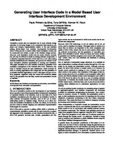
Sample input data for this user code are shown in Fig.3. This input data represents the human body phantom (Fig.4) used for correcting the efficiency of a whole body counter (human counter) at Tokyo University. (7) The phantom comprises 13 acrylic boxes filled by water. Four plastic scintillators are placed below the phantom. The room wall is iron and is covered by an acrylic inner liner. A NaI scintillator was placed above the phantom as a monitor. The parts of the phantom are grouped into eleven universes and are aligned by using two nested arrays for a convenience to change the phantom geometry. CONCLUDING REMARKS A sample user code for EGS4 with the MARS geometry system is presented. With this system, an electromagnetic cascade simulation with EGS4 can be easily performed in complex and reciprocal geometries.
5
REFERENCES (1) W.R.Nelson, H.Hirayama, and W.O.Rogers : THE EGS-4 CODE SYSTEM, SLAC-265(1985) (2) M.B.Emmett, "The MORSE Monte Carlo Radiation Transport Code System," ORNL-4972(1975) (3)
J.T.West and M.B.Emmett," MARS: A Multiple Array System Using Combinatorial Geometry," NUREG/CR-0200, Vol.3,sect.M9, (1980)
(4)
"SCALE-3 A Modular Code System for Performing Standardized Computer Analyses for Licensing Evaluation," RSIC CCC-466,(1981)
(5) M.B.Emmett, "PICTURE: A Printer Plot Package for Making 2-D Pictures of MARS Geometries,"NUREG/CR-0200, Vol.3,sect.M13, (1980) (6) Y.Yamaguchi, DEEP Code to Calculate Dose Equivalents in Human Phantom for External Photon Exposure by Monte Carlo,JAERI-M 90-235(1990) (7) M.Togo, private communication.
6
Table A.1. Input Required for Each Body Type (1/2) ──────────────────────────────────────────────────── Body Type ITYPE LALP Real Data Defining Particular Body ──────────────────────────────────────────────────── Box BOX LALPos assigned Vx Vy Vz H1x H1y H1z by the user or H2x H2y H2z H3x H3y H3z Right Parallelepiped
RPP
Sphere Right Circular
Xmin
Xmax
Ymin
Ymax
Zmin
Zmax
SPH
Vx
Vy
Vz
R
--
--
RCC
Vx
Vy
Vz
Hx
Hy
Hz
R
--
--
--
--
--
Vx
Vy
Vz
Hx
Hy
Hz
R1x
R1y
R1z
R2x
R2y
R2z
Cylinder Right Elliptical
REC
Cylinder
by the code if left blank.
Ellipsoid
ELL
V1x R
V1y ---
V1z ---
V2x ---
V2y ---
V2z ---
Truncated Right Cone
TRC
Vx Rl
Vy R2
Vz --
Hx --
Hy --
Hz --
Right Angle Wedge
WED or RAW
Vx H2x
Vy H2y
Vz H2z
Hx H3x
Hy H3y
Hz H3z
Arbitrary Polyhedron
ARB
V1x V1y V1z V2x V2y V2z V3x V3y V3z V4x V4y V4z V5x V5y V5z V6x V6y V6z V7x V7y V7z V8x V8y V8z Face Descriptions (See note below) ────────────────────────────────────────────────────── NOTE: The arbitrary polyhedron input contains a four-digit number for each the six faces of an ARB body.
Table A.1. Input Required for Each Body Type (2/2) ──────────────────────────────────────────────────── Body Type ITYPE LALP Real Data Defining Particular Body ──────────────────────────────────────────────────── Alternate Body BPP Xmin Xmax Ymin Ymax Zmin Zmax Descriptions θ1 θ2 θ3 WPP Xmin Xmax Ymin Ymax Zmin Zmax θ1 θ2 θ3 Torus
TOR
X0 FXYZ
Y0 θ1
Z0 θ2
R
a
b
General Ellipsoid
GEL
Vx R2x
Vy R2y
Vz R2z
R1x R3x
R1y R3y
R1z R3z
Truncated right elliptical cone
QUA
a g
b h
c z1
d z2
e
f
Termination of Body END Input Data ────────────────────────────────────────────────────── NOTE: The arbitrary polyhedron input contains a four-digit number for each the six faces of an ARB body.
2
1. Rectangular Parallelepiped (RPP)
z
Y
Y max Z max y
X X
Z
min
min
max x
2. Sphere (SPH)
V
R
Fig. 1
Available bodies in a modified MARS geometry (1/7)
3. Right Circular Cylinder (RCC)
H
x
H
R V (V x , V y , V z )
4. Right Elliptical Cylinder (REC)
H R2
R1 V Fig. 1
Available bodies in a modified MARS geometry (1/7)
2
y
H
z
5. Truncated Right Angle Cone (TRC)
R2
H
R1
V
6. Ellipsoid (ELL)
V 2
V1
R
Fig. 1
Available bodies in a modified MARS geometry (3/7)
3
7. Right Angle Wedge (WED)
a1
a3 a2
V
8. Box (BOX)
a3
a2 a1 V x ,V y , V z
Fig. 1
Available bodies in a modified MARS geometry (4/7)
4
9. Arbitrary Polyhedron (ARB)
V
7
V
V1 Va
V 5
V 2
V4
V 3
Fig. 1
Available bodies in a modified MARS geometry (5/7)
5
6
10. Torus (TOR) θ2
z FXYZ=1
θ1 ( y , z 0) 0
y (x0, y0, z0)
θ2
x FXYZ=2
θ1 ( z0, x 0 )
z b R
y a
(x 0, y0, z0)
θ2
FXYZ=3
θ1 (x , y ) 0 0
x
11. General Ellipsoid (GEL)
R
3
V R
R
1
R
R2
R
= 1
=
(V x , V y , V z ) ( R , R , R ) 1x 1y 1z
=
( R
, R , R ) 2x 2y 2z
3 =
( R
, R , R ) 3x 3y 3z
2
V
Fig. 1
Available bodies in a modified MARS geometry (6/7)
6
12.
Truncated right elliptical cone (QUA)
z
A'
B'
( ax + bx + c) 2 + ( dx + ez + f ) 2 = ( gz + h) 2 or 2
A Q B
P
y
x
v bZ + h eZ 1 + f P = − 1 ,− , Z1 a d v bZ + h eZ 2 + f Q = − 2 ,− , Z2 a d gZ + h gZ1 + h ( A, B) = 1 , d a gZ + h gZ 2 + h ( Aゥ , Bゥ ) = 2 , d a
Fig. 1
2
x + (bz + C ) / a y + (ez + f ) / d + =1 ( gz + h ) / a ( gz + h ) / d
Available bodies in a modified MARS geometry (7/7)
7
Fig.2 Geometry for sample input data : human.inp (Water-filled phantom on scintilator)
8
8
100
NREG : No. of material regions including void NHIST: No. of histories Material No.s and names (MEDIA in EGS4)
1 FE 2 ACRYL 3 NAI 4 AIR AT NTP 5 PLASTIC 6 SUS 7 WATER HUMAN COUNTER (CASE 1) 0 0 1 100 RPP 1 0. 125.6 RPP 2 20. 105.6 RPP 3 20.3 105.3 RPP 4 32.8 92.8 RPP 5 37.77 87.83 RPP 6 37.80 87.80 RPP 7 37.80 87.80 RPP 8 37.80 87.80 RPP 9 37.80 87.80 RPP 10 37.80 87.80 RPP 11 37.80 87.80 RPP 12 37.80 87.80 RPP 13 32.80 92.80 RPP 14 0. 15. RPP 15 0. 15. RPP 16 0. 15. RPP 17 7.5 15. RPP 18 8. 14.5 RPP 19 8. 14.5 RPP 20 0. 30. RPP 21 5.5 24.5 RPP 22 6. 14.5 RPP 23 15.5 24.0 RPP 24 0. 30. RPP 25 1.5 28.5 RPP 26 2. 14.5 RPP 27 15.5 28. RPP 28 0. 30. RPP 29 0. 30. RPP 30 0.5 29.5 RPP 31 0. 30. RPP 32 2. 28. RPP 33 2.5 27.5 RPP 34 0. 30. RPP 35 0. 30. RPP 36 0.5 29.5 RPP 37 0. 30. RPP 38 10. 20. RPP 39 10.5 19.5 RPP 40 0. 30. RPP 41 7.5 22.5
MARS card 1: Title card MARS card 2: Option card 0. 210.6 0. 260.6 MARS cards3: Body definition card 20. 190.6 20. 240.6 20.3 190.3 20.3 240.3 130. 131.5 22.8 236.3 133.5 149.0 22.8 226.58 133.53 148.53 22.83 72.83 133.53 148.53 72.86 74.04 133.53 148.53 74.07 124.07 133.53 148.53 124.10 125.28 133.53 148.53 125.31 175.31 133.53 148.53 175.34 176.52 133.53 148.53 176.55 226.55 99.90 129.90 22.8 205.80 0. 30. 0. 47.5 0. 30. 0. 33. 0. 30. 0. 102.5 22.5 30. 3. 65. 23. 29.5 3.5 33.5 23. 29.5 34.5 64.5 0. 30. 0. 47.5 20.5 30. 3.5 47.5 21. 29.5 4. 47.0 21. 29.5 4. 47.0 0. 30. 0. 33. 16.5 30. 0. 33. 17. 29.5 0.5 32.5 17. 29.5 0.5 32.5 0. 30. 0. 23. 9. 30. 0. 23. 9.5 29.5 0.5 22.5 0. 30. 0. 21. 11. 30. 0. 21. 11.5 29.5 0.5 20.5 0. 30. 0. 21. 9. 30. 0. 21. 9.5 29.5 0.5 20.5 0. 30. 0. 8. 21. 30. 0. 8. 21.5 29.5 0.5 7.5 0. 30. 0. 29.5 9.5 30. 0. 20.
Fig.3 Sample input of the UCMARS user code for a human counter (1/3)
9
RPP RPP RPP RPP RPP RPP RPP RCC END R01 R02 R03 R04 R05 R06 R18 R10 R12 R17 R19 R11 R07 R08 R09 A14 U01 A20 P21 W22 W23 U02 A15 U03 A24 P25 W26 W27 U04 A16 P17 W18 W19 U05 A43 P44 W45 W46 U06 A28 P29 W30
42 43 44 45 46 47 48 49
8. 22. 10. 29.5 0.5 0. 15. 0. 30. 0. 0. 7.5 22.5 30. 3. 0.5 7. 23. 29.5 3.5 0.5 7. 23. 29.5 34.5 -1.0D+08 1.0D+08 -1.0D+08 1.0D+08 -1.0D+09 1.0D+09 -1.0D+09 1.0D+09 30.3 97.5 44.7 0. -10.2
+1 -2 +2 -3 +49 +13 +4 +6 +8 +10 +12 +7 +9 +11 +5 -6 -7 -8 -9 -10 -11 -12 +3 -49 -13 -4 -5 +48 -1 +14 +47 -14 +20 -21 +21 -22 -23 +22 +23 +47 -20 +15 +47 -15 +24 -25 +25 -26 -27 +26 +27 +47 -24 +16 -17 +17 -18 -19 +18 +19 +47 -16 +43 -44 +44 -45 -46 +45 +46 +47 -43 +28 -29 +29 -30 +30
19.5 102.5 65. 33.5 64.5 -1.0D+08 1.0D+08 -1.0D+09 1.0D+09 0. 6.35 MARS cards4:Input zone description cards Iron wall Acryl inner liner of wall NaI scintillator Boundary of ARRAY 1 Acryl plate below phantom Plastic scintillator 1 Plastic scintillator 2 Plastic scintillator 3 Plastic scintillator 4 Air between scinti. 1 and 2 Air between scinti. 2 and 3 Air between scinti. 3 and 4 SS wall of scintillator Air in room External void Outer boundary of universe 1 External media ( -1000) of univ.1 Outer boundary of universe 2
External media ( -1000) of univ.2 Outer boundary of universe 3 External media ( -1000) of univ.3 Outer boundary of universe 4
External media ( -1000) of univ.4 Outer boundary of universe 5
External media ( -1000) of univ.5 Outer boundary of universe 6
External media ( -1000) of univ.6 Outer boundary of universe 7
Fig.3 Sample input of the UCMARS user code for a human counter (2/3)
10
U07 +47 -28 External media ( -1000) of univ.7 A31 +31 -32 Outer boundary of universe 8 P32 +32 -33 W33 +33 U08 +47 -31 External media ( -1000) of univ.8 A34 +34 -35 Outer boundary of universe 9 P35 +35 -36 W36 +36 U09 +47 -34 External media ( -1000) of univ.9 A37 +37 -38 Outer boundary of universe 10 P38 +38 -39 W39 +39 U10 +47 -37 External media (-1000) of univ.10 A38 +40 -41 Outer boundary of universe 11 P39 +41 -42 W40 +42 U11 +47 -40 External media (-1000) of univ.11 END 59*1 MARS card 5 : Region card (not used) 15*0 2*1 5*2 2*3 5*4 5*5 5*6 4*7 4*8 4*9 4*10 4*11 M A R S c a r d 6 : U n i v e r s e c a r d 1 2 3 -1 2 5 5 5 5 4 4 4 6 4 0MARS cards7 : Media card 4 -1000 media for universe 1 4 2 7 7 -1000 media for universe 2 4 -1000 media for universe 3 4 2 7 7 -1000 media for universe 4 4 2 7 7 -1000 media for universe 5 4 2 7 7 -1000 media for universe 6 4 2 7 -1000 media for universe 7 4 2 7 -1000 media for universe 8 4 2 7 -1000 media for universe 9 4 2 7 -1000 media for universe 10 4 2 7 -1000 media for universe 11 3 1 3 1 1 5 0 2 MARS card 8 : Array size specifications input (Array 1 :3x1x3 as XxYxZ) (Array 2 :1x1x5 as XxYxZ) 101$$ 1 2 1 3 4 3 5 -2 6 M A R S c a r d 9 : Array content description (1) 102$$ 7 8 9 10 11 T M A R S c a r d 9 : Array content description (2) 11*0 MARS card10 : Universe type(all combinatorial)
Fig.3 Sample input of the UCMARS user code for a human counter (3/3)
11
APPENDIX : FREE-FORM COMBINATORIAL MARS INPUT INSTRUCTIONS (This instructions are re-typed from NUREG/CR-0200, section M9) A.1
TITLE* CARD
FORMAT (15A4) A.2
OPTIONS CARD (four entries required) IVOPT- Volume option not implemented - enter 0. IDBG - Debug print option if positive; otherwise, enter 0. IBOD - Body numbers are assigned by the user if IBOD is greater than zero; otherwise, enter 0. NAZ
- Number of zones to be added to the data storage for next zone of entry memory table. Enter any large number if extra storage is required. Default value allows for five zones to be entered from any single code zone. This option is normally not required; enter 0.
A.3
BODY DEFINITION CARDS Each new body must start on a new card. The allowable body types are given In Table A.1
along with the required input variables to describe each body. An END card must be used to signify the end of the body definition cards. For each body, the following input is required: ITYPE - Specifies the alphanumeric body type or END to terminate reading of body data (for example, BOX, RPP, ARB, RCC, etc.) IALP - Body number assigned by the user if IBOD is greater than zero; otherwise, it is not entered. FPD(I)- Real data required for the given body as show in Table A.1. This data must be in cm. A.4
INPUT ZONE DESCRIPTION CARDS Each new zone must start on a new card. A three-character title should be given for each
new input zone (not necessarily unique) which must start with an alpha-type character. An END card must be used to signify the end of the input zone description cards. For each input zone, the data needed is the title and zone data. Input zone numbers are assigned sequentially. IALP
- The three-character title for the zone where the first character is a letter.
IIBIAS(I) - Specify the "OR" operator if required for the JTY(I) body. JTY(I)
- Body number with the (+) or (-) sign as required for the zone description.
Example: PEL +1 CLD +2 -1 H2O +3 -2 END A.5
REGION CARD One entry is required for each input zone. This specifies the importance region each
input zone is inside. This determines which set of weights for splitting, Russian roulette, and path length stretching to use in each zone during tracking. A.6
UNIVERSE CARD This array specifies which universe each input zone is inside. One entry is required for
each input zone. The entry must be either a zero or a positive integer. A negative entry is not valid. Each universe, with the exception of the absolute universe, must contain one and only one zone with a -1000 media. The absolute universe cannot contain any -1000 media zone. A.7
MEDIA CARD This array specifies the media contained in each input zone. One entries required for each
input zone. If the entry is positive, it references a valid cross section mixture or a reflected boundary, MEDALB. If the entry is negative, it references a valid array number as the absolute value of the entry. If the entry is -1000, it references a universe external boundary media. If the entry is 1000, it references an internal void. If the entry is 0, it references an external void. A.8
ARRAY SIZE SPECIFICATIONS INPUT An array is a regular rectangular lattice composed of rectangular cells of
arbitrary
content. The size of each array should be entered as NXMAX, NYMAX, by NZMAX. Arrays are sequentially named as they are entered, starting with 1. The array size entered should include any vacant cells in the array, if any are present. After the size of the last array has been entered, a zero should be entered to terminate the entries. Zero is an illegal entry for an array size. After the zero terminator has been entered, a single integer parameter is entered to determine the means of entering the array specification list. If no array is to be described, only the zero terminator is required. NXMAX i - The number of cells along the x-axis of array i NYMAXi - The number of cells along the y-axis of array i NZMAXi - The number of cells along the z-axis of array i
2
followed by a "0 terminator" LOP
- array specification input option (required) = 0
Free-Form Input, FFREAD, type specification
= 1 Standard KENO Mixed Cell (BOX) Orientation Cards = 2 Standard FIDO Integer Array Input Specification Example:
15
15
1
6
5
2
7
7
1
0
0
This example describes three arrays. Array 1 will be a 15 by 15 by 1 array. Array 2 will be a 6 by 5 by 2 array. Array 3 will be a 7 by 7 by 1 array. Zero terminates the array size entries. The last zero entered selects the free-form input specification method of describing the array contents. --End of Geometry Input if No Arrays are Modeled-A.9
ARRAY CONTENT DESCRIPTION The contents of each cell of each array must be defined. All contents of Array 1 are
defined, then Array 2, etc. The method of entering this data is determined by IOP in Sect. A.8 input. There are three possibilities for each cell entry. These are distinguished by either a positive, zero, or negative entry. A positive entry is a universe number. The universe must fit slightly in the lattice cell position it is referenced inside. The contents of universe are completely arbitrary. A negative entry is an array entry. The absolute value of the entry is the array being referenced. It must completely fill the lattice position in which it is referenced. It cannot contain any vacancies in its lattice cell positions. Repeating a subarray in a larger array in this manner dose not require any additional input. The array must, however, fit snugly in the lattice cell position. The means of entering this data is selected by the user to give flexibility in describing his arrays. The options are: 1.
IOP = 0 - Free-Form Input Option Free-form input is entered using the FFREAD notation. This allows an "*" repeat feature. Data is entered as: DO 10 M = 1, NAR (NAR is the number of arrays entered) DO 10 K = 1, NZMAX DO 10 J = 1, NYMAX DO 10 I = 1, NXMAX ...enter the contents of the ith, jth, and zth cell location for array m... 10 CONTINUE
3
All entries must be separated by a blank and data may be entered in all columns 1 through 80. Entries of the form, "L*N," means enter the value N into the input L times. This could also be done with the "R" option by entering "LRN." In both cases blanks between entries are not allowed. Example:
2
1
2
2
1
2
2
1
2
This could be the description of a 3 by 3 array of the form,
2.
2
1
2
2
1
2
2
1
2
IOP = 1 - Mixed-Cell Orientation Cards The first field contains the entry followed by three sets of three fields that are treated like FORTRAN.DO loops, followed by a field that indicates whether another set of data is to be read. The arrangement of lattice cells may be considered as consisting of a threedimensional matrix of numbers, with the cell position increasing in the positive X, Y, and Z directions, respectively. Each set of orientation data consists of the following parameters, separated by one or more blanks. LTYPE
The cell entry. LTYPE may be negative (array #), zero (empty cell), or
positive (universe #). IX1
The starting point in the X direction. IX1 must be at least 1 and less than or equal to NXMAX.
IX2
The ending point in the X direction. IX2 must be at least 1 and less than or equal to NXMAX.
INCX
The number of cells by which increments are made in the positive X direction. INCX must be greater than zero and less than or equal to NXMAX.
IY1
The starting point in the Y direction. IY1 must be at least 1 and less than or equal to NYMAX.
IY2
The ending point in the Y direction. IY2 must be at least 1 and less than or equal to NYMAX.
INCY
The number of cells by which increments are made in the positive Y direction. INCY must be greater than zero and less than or equal to NYMAX.
IZ1
The starting point in the Z direction. IZ1 must be at least 1 and less than or equal to NZMAX.
IZ2
The ending point in the Z direction. IZ2 must be at least 1 and less than or equal to NZMAX.
4
INCZ
The number of cells by which increments are made in the positive Z direction.
INCZ must be greater than zero and less than or equal to NZMAX. ISTP
= 0, read another set of data, = 0, do not read any more mixed-cell orientation data.
An important feature of this type of data description is that, if any portion of an array is defined in a conflicting manner, the last card to define that portion will be the one that determines the array's cell type configuration. To utilize this feature, one can fill an entire array with the most prevalent cell type and then superimpose the other cell type in their proper places to accurately describe the array. the last set of mixed-cell orientation data must have a non zero entry in the last field. 3.
IOP = 2 - Standard FIDO Array Input The array being entered is integer; therefore, it is a "S" or "SS" array. The array may be entered in the standard free-form FIDO format. The description for each lattice array is entered as a single array block with FIDO. The FIDO integer array number entered is the array number being described plus 100. The data is entered and each array description is terminated with a "T." All standard FIDO repeat options are available for entering the data. Array 1 would be entered as the "101$$" FIDAS array terminated with a "T." The process would continue until all array descriptions have been entered. The format for the data entry is the same as the description for free-form input. All x entries for the first y row and first z level are entered, then all x entries for the second y row and first z level are entered. This process continues until the entire first z level has been described. Then the geometry array description or given array is terminated with a "T."
A.10
UNIVERSE TYPE One entry is required for each universe modeled in the combinatorial geometry, starting
with Universe 1. The entries should be either a zero or a 1: a zero if the universe is "combinatorial" and a 1 if the universe is "simple." A "simple" universe is a universe composed of concentric zones, where every zone completely surrounds the zone inside of it. Furthermore, input zone in a simple universe may be only one code zone and may be described by only one or two bodies. Tracking through "simple" universes is aboat 30% or more faster than through regular combinatorial geometry tracking, although the modeling capability is limited. Simple universes maybe combined with regular combinatorial universes in arrays without any problems.
5