Ultrasensitive MEMS-based Inertial System Lukas Novak
Pavel Neuzil*, Jing Li, Matthew Woo
Czech Technical University in Prague Prague, Czech Republic
[email protected]
Institute of Microelectronics Singapore *
[email protected]
Abstract—In this paper we present the design and fabrication of sensitive capacitive MEMS-based accelerometer and its high signal-to-noise ratio read-out electronic circuit. The combination of sensitive accelerometer and sensitive read-out electronics resulted in the system sensitivity of 135 V/G with the detection limit of 22 µG acceleration or 0.05 degree inclination.
I.
INTRODUCTION
MEMS-based accelerometers have been developed for at least two decades [1]. They became one of the first MEMSbased commercially successful products (air-bags) [2]. Most sensitive accelerometers are based on tunneling effect [3]. This type is rather complex from both fabrication as well as control point of view. Is there a way to achieve similar sensitivity using cost-effective accelerometer? As an alternative to the tunneling device, we have explored a conventional bulk micromachining technology using SOI substrate in combination with high signal-to-noise ratio electronics using lock-in amplification. II.
EXPERIMENTAL
An ultra sensitive capacitive MEMS-based dual axis accelerometer [4] capable of detecting acceleration in tens of µG level was designed and fabricated using 30 µm thick silicon-on-insulator (SOI) substrate. For the accelerometer sensor we have designed and manufacture compact sensitive electronic read-out system with noise suppression techniques employed. The high overall sensitivity of accelerometer system was achieved by pushing both MEMS as well as the read-out electronics to its limit.
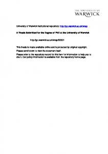
Al1%Si4%Cu layer was subsequently sputtered and patterned to cover all opened contact areas. The metal layer was then sintered in a forming gas for 20 min at 450 oC. SiO2 was patterned again and deep reactive ion etching was employed to etch silicon in order to form the interdigitated electrodes, isolation trenches as well as release holes in an accelerometer proof mass. Photoresist was removed and BOX was etched by HF vapor process using Primax system. The MEMS has large proof mass of 3.3x10⁻⁷ kg and weak spring constant of 14 Nm-1 with fully differential architecture. Overall device footprint is 4×4 mm2. The device consists of two pairs of folded springs with common proof mass (see Fig. 1). Each axis is balanced by two springs and has two capacitors each divided into two halves which are electrically connected on the chip to form single capacitor. Axis X consists of capacitors C10 and C11 where C10 is formed by its halves C10A and C10B and C11 by halves C11A and C11B. Axis Y consists of capacitors C20 and C21 where C20 is formed by halves C20A and C20B and C21 by halves C21A and C21B. The scanning electron microscope (SEM) photograph of fabricated device is shown in Fig. 2. B. Read-out electronical circuit The sensitive read-out electronics is based on charge amplifier, differential amplifiers and lock-in amplifiers. The use of these techniques resulted in high overall gain with highsignal to noise ratio.
MEMS-based accelerometer The dual axis capacitive MEMS-based accelerometer was fabricated by bulk micromachining technique. Starting substrate was 200 mm diameter silicon-on-insulator wafers with 1 µm buried oxide (BOX) and 30 µm thick boron doped top silicon layer. The wafers were first covered with 1 µm thick silicon oxide deposited by plasma enhanced chemical vapor technology process (PECVD). SiO2 layer was then photolithographically patterned to open contacts to the top silicon layer. It was implanted with boron, photoresist was removed and boron activated by rapid thermal processing.
C20A
C20B
A.
We would like to thank the Agency for Science, Technology and Research, Singapore and the funding of Czech Technical University in Prague Nr. CTU0914113, for the financial support.
978-1-4244-5335-1/09/$26.00 ©2009 IEEE
C11A
C10A
y x C11B
C10B
C21A
C21B
Figure 1. Principle of a dual axis capacitive accelerometer. Each axis is balanced by two springs and has two capacitors each divided into two halves which are electrically connected on the chip to behave as one capacitor.
552
IEEE SENSORS 2009 Conference
TABLE I.
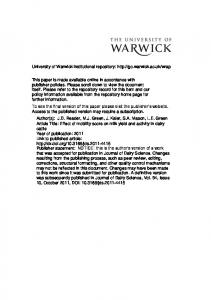
Figure 2. SEM image of fabricated device. Inset with the black border shows detail of the electrode area.
The nominal capacitance of MEMS capacitors is in the order of tens pico Farads and the capacitive change due to the acceleration or inclination is only few femto Farads FS (Full Scale). Therefore, it is necessary to use high amplification factor of the processing electronics and also to eliminate the nominal capacitance which does not carry any information about acceleration. The MEMS capacitors are powered by reference sinusoidal signal with the amplitude of 1 V and frequency of 5 kHz. The reason for this AC powering is the use of charge amplifiers and lock-in amplifiers (described later). First, for the accelerometer axis X: the MEMS split capacitors C10 (formed by halves C10A and C10B) and C11 (formed by halves C11A and C11B) are connected to their own charge amplifiers CA1 and CA2 based on AD822 integrated circuit (Analog Devices, Inc.) which convert capacitance to voltage (see Fig. 3). Consequently, this output voltage is subtracted in the differential amplifier DAX with the gain of 883 (see Table I for individual amplification factors) to suppress the nominal capacitance of accelerometer and amplify the capacitance change due to proof mass displacement along the corresponding axis caused by acceleration (inclination). Differential amplifier DAX is based on AD8221 integrated circuit (Analog Devices, Inc.).
AMPLIFICATION FACTORS OF THE READ-OUT CIRCUIT
Charge amplifier CA
Differential Amplifier DA
Operational Amplifier OA
Lock-In Amplifier
1/5.6/10-12
2*883
4.3
4/π
The output voltage is then filtered by a high-pass filter to eliminate DC voltage caused mostly by the offset voltages of charge amplifiers. Without this DC voltage suppression, the second amplifier may be saturated and thus the linearity of the electronic processing chain could be compromised. The filtered voltage is further amplified by a factor of 4.3 by a second amplifier OAX consisted of AD8221 integrated circuit (Analog Devices, Inc.). This amplified voltage is fed to modulator/demodulator AD630 (Analog Devices, Inc.) where is multiplied by the absolute value of the reference signal and amplified by a factor of 2. Finally, the demodulated voltage is filtered by a low-pass filter of the 3rd order with the cut-off frequency of 234 Hz to eliminate the upper harmonics. Similarly is processed the axis Y by capacitors C20 and C21, and amplifiers CA3, CA4, DAY, OAY and lock-in. The combination of a modulator and a low-pass filter form the lock-in amplifier which significantly increased the signalto-noise ratio and thus allows higher gain of whole electronic chain. This lock-in technique suppressed offset errors and noise of charge amplifiers, differential amplifiers and operational amplifiers. The MEMS accelerometer in QFP24 socket was mounted on the printed circuit board (PCB) with the lock-in amplifier. Photograph of the PCB with the accelerometer in the center of a white ring is shown in Fig. 4. III.
RESULTS
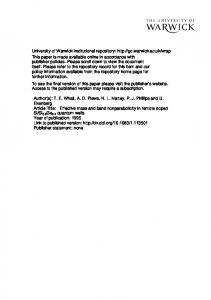
The system was mounted on a tilted platform and calibrated by tilting the platform with 2.5 degree step while recording the voltage output starting from 0 degree tilt (see Fig. 5). The system response was found to be 135 V/G with 3 mV noise level corresponding to the detection limit of 22 µG.
Figure 3. Schematic diagram of the sensor read-out circuit. Charge amplifiers are converting the accelerator capacitance into corresponding voltages. Their difference corresponding to the location of the accelerometer proof mass is subsequently demodulated and filtered by a low pass filter to increase signal-to-noise ratio.
Figure 4. Photograph of the PCB with the accelerometer in the center of a white ring.
553
1.5
The accelerometer capacitance change due to the acceleration was calculated to be 78 fF/G. The sensitivity is so high that the device is capable of detecting knocking on the floor while being mounted on a massive antivibration table (see Fig. 6). The frequency of detected vibration is 146.5 Hz as per Fourier transform extraction (inset of Fig. 6).
Output (V)
1.0
0.5
IV. 0.0
-0.5 0
25
50
75
100
125
150
175
Time (s) Figure 5. Sensor response to the stage tilt as function of time with 2.5 degree change per step starting from 0 degree tilt. The device sensitivity was calculated to be 135 V/G.
This ultra high response to acceleration comparable with the tunneling device results from a combination of sensitive MEMS device and sensitive read-out circuit based on lock-in amplification technique and it was accomplished by readily available integrated circuits. The device can be used as a costeffective alternative of tunneling accelerometer for seismic detection, or as an inclinometer with 0.05 degree resolution. ACKNOWLEDGMENT We would like to thank Vitek Zahlava (Czech Technical University in Prague) for the PCB design and assembly. REFERENCES
First fundamental = 146.5 Hz [1] [2] 60
-200
[3]
50
Amplitude (mV)
Acceleration (mG)
0
-400
40
[4]
30 20 10
-600
0
0
50
100
150
200
250
Frequency (Hz)
0
50
100
150
200
CONCLUSION
250
Time (ms) Figure 6. System response to the knocking of the antivibration table. The frequency of detected vibration is 146.5 Hz as per Fourier transform extraction (inset).
554
Petersen, K.E., Silicon as a mechanical material, Proceedings of the IEEE, May 1982, Vol. 70, Iss. 5, pp. 420 - 457 , ISSN: 0018-9219 V. Josselin, P. Touboul and R. Kielbasa, Sensors and Actuators A: Physical 1999 78(2-3), pp.92–98 F. T. Hartley and Paul M. Zavracky, http://trsnew.jpl.nasa.gov/dspace/bitstream/2014/35976/1/93-1706.pdf Greenwood, J.C., A silicon bulk micromachined capacitive force feedback accelerometer, Silicon Fabricated Inertial Instruments (Digest No: 1996/227), IEE Colloquium on, 2 Dec. 1996, pp. 6/1 - 6/2