Inventor's Guide insert accessories accessories sensor accessories ultrasonic
sensor kit • 1. Ultrasonic Sensor Kit. “Ultrasonic” refers to very high-frequency ...
sensor accessories
ultrasonic sensor kit
ultrasonic module x 1
screw x 2 (8-32, ³/8")
keps nut x 2
Limited 90-day Warranty This product is warranted by Innovation One against manufacturing defects in material and workmanship under normal use for ninety (90) days from the date of purchase from authorized Innovation One dealers. For complete warranty details and exclusions, check with your dealer. Innovation One, Inc. 350 North Henderson Street Fort Worth, TX 76102 11/04 Printed in China 0405
Inventor’s Guide insert © 2005 Innovation One. All Rights Reserved.
INSERT THESE PAGES at the back of the Sensor Chapter in your Vex Inventor’s Guide.
YOU MUST HAVE A PROGRAMMING KIT TO USE THIS SENSOR!
accessories
Ultrasonic Sensor Kit “Ultrasonic” refers to very high-frequency sound – sound that is higher than the range of human hearing. Sonar, or “Sound Navigation And Ranging,” is an application of ultrasonic sound that uses propagation of these highfrequency sound waves to navigate and detect obstacles. Sonar has a wide variety of applications and a wide variety of users, from submarines avoiding underwater obstacles to hungry bats looking for their dinner!
ultrasonic sensor kit • 1
Vex and Vex Robotics Design System are trademarks of Innovation One.
sensor accessories
ultrasonic sensor kit, continued Technical overview
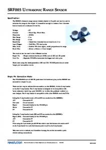
The ultrasonic sensor determines the distance to a reflective surface by emitting high-frequency sound waves and measuring the time it takes for the echo to be picked up by the detector. The ultrasonic sensor can determine the distance to an object between 3cm and 3m away; closer than 3cm will result in the sound waves echoing back to the sensor before the detector is ready to receive.
Emit sound wave
Detect sound wave
The number of seconds for the sound wave to be detected = round trip delay
The ultrasonic sensor actually consists of two parts: an emitter, which produces a 40kHz sound wave; and a detector, which detects 40kHz sound waves and sends an electrical signal back to the microcontroller. In order to determine the distance to an object, it is necessary to implement a timing loop in your microcontroller code to measure the length of time required for the sound wave generated by the emitter to traverse the distance to the object. The distance to the object can then be calculated with the following formulas:
Distance to object = ½ (speed of sound) X (round trip delay) [Note: speed of sound varies with altitude and temperature. At sea level and room temperature, it’s approximately 344.2 m/s or 1135 ft/s. It will increase with temperature and decrease with altitude.] Therefore
Distance in feet = 567.5 ft/s X (round trip delay) or Distance in meters = 172.1 m/s X (round trip delay)
ultrasonic sensor kit • 2
Inventor’s Guide insert
accessories
1
sensor accessories
ultrasonic sensor kit, continued Technical overview
The steps your robot’s program will have to follow in order to calculate the distance to an object are: 2. The ultrasonic sensor generates a 250 microsecond ultrasonic pulse.
accessories
1
1. The Vex microcontroller sends a “start” signal to the ultrasonic sensor.
3. The ultrasonic sensor sets its output signal to +5V, thus sending a “high” signal to the microcontroller. In digital terms, this is a “1”.
4. A timing loop on the microcontroller begins, counting the seconds. This will be the “round trip delay” in the distance equation.
5. The ultrasonic sensor picks up the echo from the 250 microsecond pulse.
7. The Vex microcontroller exits the timing loop and uses the round trip delay to calculate the distance to the object.
6. The ultrasonic sensor sets its output signal to 0V, thus sending a “low” signal to the microcontroller. In digital terms, this is a “0”.
Inventor’s Guide insert
ultrasonic sensor kit • 3
sensor accessories
ultrasonic sensor kit, continued Connecting the ultrasonic sensor to the microcontroller
The ultrasonic module has two three-pin connectors that will each plug into an interrupt port on the Vex Microcontroller. These can be adjacent ports, but do not have to be. The connector labelled “INPUT” is the trigger output of the Vex microcontroller; the ultrasonic module receives a start signal from the Vex microcontroller on this line. The connector labelled “OUTPUT” is the echo response from the ultrasonic detector; this is the line through which the Vex microcontroller receives output from the detector, indicating that it has picked up an echo.
3
Reprogramming the microcontroller to enable the ultrasonic sensor to generate a “ping”
Start by plugging the “INPUT” and “OUTPUT” connectors into any two ports in the Interrupts bank on the Vex Microcontroller.
In order for your robot to be able to read the sensor, you will have to reprogram the microcontroller. Sample code to help you get started is available on the VexLABS.com website. Refer to the Programming chapter in your Vex Inventor’s Guide for information on how to add or change code.
ultrasonic sensor kit • 4
Inventor’s Guide insert
accessories
2