Dec 1, 2004 - for example, Ambient [13] uses a barb that is somehow related to i. above .... that action in(! x)@l1 can consume any datum l2 at l1; l2 will then ...... adjacent 'complementary' actions can be deleted (by using a ...... rec X. think .i
It models the anchor element in HTML. The links relationship can have parameters which are modeled as attributes in the relationship. The submit relationship is ...
In this paper we propose a framework dedicated to the development .... within web technologies such as web servers. The Globus ... YML rests on a dedicated programming lan- ..... rent approach used by existing back-end executes a YML.
The overall aim of this paper is to illustrate that formal analysis tools can be used directly by designers of applications for global computing. To this end,.
development and on the existing software resources of HPF. and MOVIE. We are ... Systems software such as X/Motif/OpenLook, DPS/NeWS,. PEX/GL, UNIX ...
system), Apache (web server), PHP (programming language) and MySQL (database). The Persistence. Domain is an intermediate abstraction that decou-.
University of Vermont, Burlington, VT 05405. Email: [email protected]. ... and also receives support from the New Jersey Commission on Science and Technology.
Grid technology is becoming more common and several com- putational Grids have ... jobs, see Table I. Typically existing large-scale computers from different ...
the waterfall model, the spiral model, the Rational. Unified Process (RUP) or Extreme Programming (XP) to meet the challenges of system development. While.
Abstract. Software development evolution is a history of permanent seeks for raising the .... A xUML model is therefore independent of software organization and ...
At sd&m (a medium size software company in Munich,. Germany) we conducted a study of best practices concerning the analysis phase. The aim was to find out.
relevant entities of a domain in an ontology of that domain using an ontology specifi ..... Henderson-Sellers and Barbier disagree with this statement showing the ...
Feb 17, 2006 - This profile generalises the Rhapsody UML profile by increasing the ...... Rational/IBM: Rose real-time development environment. http://.
Alternatively, an IF representation can be provided as input to the TGV. (Test Generation with Verification) tool [?]. In this case, the state diagram com- ponent of ...
This transformation does not preserve semantics considering class dia- grams without OCL ..... Another work [Gogolla and Richters 1998] introduces a number of ...
Model-driven development method based on UML activities and ESMs ... Figure 2 shows an activity which sends SMS messages to mobile phone users.
discusses features of such a process framework with an eye towards approaches such as Fusion, OPEN and the Rational Unified Process. Acknowledgement.
In the last years, some proposals to extend the UML for database design have been ... that specifies how specific UML model elements are customized and ... UML 1.4 [10] includes a standard profile for modeling software development ...
whole software development life-cycle. Software. Performance Engineering (SPE) is a system- atic and .... the Canadian software engineering scholars and.
mental results on the âcloud-burst problemâ, and we discuss some related work .... We assume that the company has a private cloud infras- tructure which runs ...
information there is a compelling need to interleave meta-programming .... fun double x = ; ...... http://www.cis.upenn.edu/ mwh/papers/loadcalc.pdf). 24.
Dec 4, 2008 - sociated with two level quantum systems interacting with their nearest neighbours are .... Proposed by Benjamin [11], this is one of the simplest ...
Business modelling, UML diagrams, Extensibility ... complementary paths: a critical study of UML diagrams and a description of .... fashion (Davenport 1993).
Jul 12, 2000 - transformation of class diagrams into STs with product and sum sorts that re ...... M. Gogolla, M. Richters, Transformation Rules for UML Class ...
part of modern software development practice. Modelling permits ... dominant modelling language for object-oriented software systems: 1. Desire to take ...
UML for Global Computing? Hubert Baumeister1 , Nora Koch1 , Piotr Kosiuczenko1 , Perdita Stevens2 , and Martin Wirsing1 1
Institut f¨ ur Informatik Ludwig-Maximilians-Universit¨ at M¨ unchen 2 Informatics (South), University of Edinburgh, GB {baumeist, kochn, kosiucze, wirsing}@informatik.uni-muenchen.de [email protected]
Abstract. Global systems – systems which may operate over transient networks including mobile elements and in which computation itself may be mobile – are gaining in importance. Nevertheless, the means for their modelling are still underdeveloped. The Unified Modelling Language (UML) is well developed for convenient modelling of behavior, but is not yet so useful for modelling aspects of design relevant to global systems, such as mobility. Non-functional requirements such as performance and security also assume an increased importance in the context of global systems, and here too, UML requires enhancement. In this paper we present an extension to UML class, sequence and activity diagrams to model mobile systems. We also describe extensions to model performance and security characteristics. We will describe how, wherever possible, we reuse existing work in these areas.
1
Introduction
The latest developments in information and communication technology impose enormous challenge of defining and exploiting dynamically configured systems of mobile entities that interact in novel ways with their environment to achieve or control their computational tasks. The emergence of the World Wide Web provides new computational paradigms in which computation is distributed over the net and highly dynamic, with the network itself changing continously. The network topology, which was carefully hidden in LAN, starts to play a fundamental role. This situation fostered new concepts like global and mobile computing. If dependable global systems are to be built efficiently, it is essential to be able to model their requirements and their design, since modelling is an essential part of modern software development practice. Modelling permits designers to solve many problems at an early stage of development that might otherwise be discovered much later. Models are also essential to the maintenance of systems and to their analysis. ?
This research has been partially sponsored by the EC 5th Framework projects: AGILE (IST-2001-32747) and DEGAS (IST-2001-32072).
The Unified Modeling Language (UML) [13] is a widely adopted standard for modelling object-oriented software systems. It consists of several diagram types providing different views of the system model. UML is a semi-formal language defined by a combination of UML class diagrams, natural language and formal constraints written in the object constraint language (OCL). An important feature of UML is that it was designed to be specialised, and mechanisms for defining specialised variants of UML are available. In order to use UML to model global applications we have to consider both the nature of the applications themselves and the issues which will most occupy their designers. One of the key feature of global applications which distinguishes their models from models of most other applications is their use of mobility. In this paper we present two extensions of UML diagrams for modeling mobile systems. The first notation, the so called Sequence Diagrams for Mobility (SDM), add appropriate primitives for modelling of object topology and mobility and can be seen as a generalization of UML Sequence Diagrams [12]. The second one extends in a similar way UML Activity and Object Flow Diagrams [2]. The idea of our approach is similar to the idea of ambients or Maude in that a mobile object can migrate from one location to another, that it can be the location for other mobile objects and that it may interact with other objects. Locations can be arbitrarily nested, generalizing the limited place-agent nesting of most agent and place languages. We introduce into UML the concepts of location, mobile object, mobile location, move action and clone action. These concepts are defined by using UML stereotypes, tagged values and OCL-constraints. There are several other issues which may occupy designers of mobile systems, but two areas seem to be of major concern. Global computing raises particular concerns for security, where the system includes mobile devices which cannot be trusted. Equally, in an environment where network connections may behave, fail and recover unpredictably, performance is harder to predict through intuition alone. Another reason why performance considerations may be important is that battery life of the mobile devices used may be a limiting factor. In Sect. 2 we explain or choice to use the UML and discuss its extension mechanism. In Sect. 3 we present the basic concepts of mobile systems followed in Sect. 4 and Sect. 5 by the extension to UML Sequence and Activity Diagrams to model mobile systems. Security is considered in Sect. 6, performance in section 7.
2
UML extensions
One of the basic ideas of the AGILE [1] and DEGAS [5] projects is to allow developers to design global applications using as far as possible the design notation which is familiar to them: the Unified Modelling Language. There are several reasons for this, generally consequences of the fact that UML is now the dominant modelling language for object-oriented software systems: 1. Desire to take advantage of existing expertise 2. Availability of a wide range of commercial and free tools
3. Availability of books and training, ability to recruit people already familiar with UML 4. Perception that UML has a good blend of precision and flexibility for most purposes (though there are some concerns) However, UML, as defined by the OMG, is not in itself adequate for the modelling of global applications and for analysis of their properties including mobility, performance and security. UML does not contain features that permit the description of how parts of the system are mobile, nor that permit the expression of security or performance features. Accordingly we have decided that we need to define a variant of UML which extends the language’s capabilities to express mobility, performance and security features. The next question is how to specialise UML. We could of course define a variant of UML in any way which suited us. However, UML does provide a standard mechanism for extending UML to suit the needs of different application areas. One defines a UML profile, which is essentially a dialect of UML; see [13] for details. Several profiles for different application areas have themselves been standardised by the OMG, and many more have been defined by their users. There are several advantages of using UML extenxion mechanisms, in particular: – – – –
Not needing to define a language specialisation mechanism of our own Acceptability within the UML community Makes it straightforward to build on existing UML profiles Potential availability of tools supporting profiles
Sometimes, the mechanisms for defining profiles are not sufficiently expressive for defining the desired UML extensions. For example, it is difficult to define a new diagram type in a profile unless it is closely related to an existing UML diagram type. In such cases, one can choose instead to extend the UML metamodel. This gives a heavyweight extension of UML, which will not automatically be supported by tools. At present, the main commercial tools do not support semantics of user defined profiles. However, there are signs that this is changing; for example, Artisan Software has recently released a version of their tool with support for profiles. Therefore the approach we take to extending UML within the AGILE [1] and DEGAS [5] projects is to define a profile that meets our needs, wherever possible, both in order to save ourselves effort and in order to maximise the acceptance of our work in the wider community. DEGAS builds exclusively on profiles that already exist, whereas AGILE introduces its own notation when necessary.
3
Mobility Concepts
Mobility is one of the most important aspects of global computation. Code mobility emerged in some scripting languages for controlling network applications
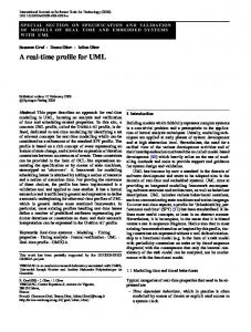
like Tcl and is one of the key features of the Java programming language. Agent mobility has been supported by Telescript, AgentTcl, or Odyssey (cf. e.g. [8]). In addition, hardware can be mobile too. Mobile hosts like laptops, WAPs and PDAs can move between networks. Moreover, entire networks can be mobile, like for example IBM’s Personal Area Network (PAN) and networks of sensors in airplanes or trains. For example, Fig. 1 shows in an informal way a person having a PAN who boards an airplane, flies from one location to another and deplanes.
2
3
1
4
Fig. 1. Nested mobile networks.
Mobile computations can cross barriers and move between virtual and physical locations, therefore they can turn remote calls to local calls avoiding the latency limits. But there is a price to pay since the administrative barriers and multiple access pathways interact in very complex ways. This requires special means for the specification and implementation of mobile systems. There exist already some extensions to UML for modeling mobile systems. In [16] an extension of collaboration diagrams is presented to model dynamic change of the composition relationship. It defines a form of aggregation link between objects — a component link — with the additional semantics that a component link may change over time. In addition, it proposes the use of component boundaries to emphasize the relationship between a component and its immediate components. It is an interesting approach, but it modellsm mobility in a rather indirect way and does not explain how these extensions fit into the UML metamodel.
Another extension is presented in [11]. It is similar to the early idea of Use Case Maps [3]. Stereotyped classes and packages are used to model mobility. Objects moving from one location to another are modeled by stereotyped messages. This approach can be used when there are only two kinds of objects: mobile objects and static locations. It is not well suited for modeling objects which are both locations and mobile. In the following we introduce the main structural concepts for modelling mobility we use in this paper: locations, mobile objects and actions moving mobile objects. 3.1
Locations
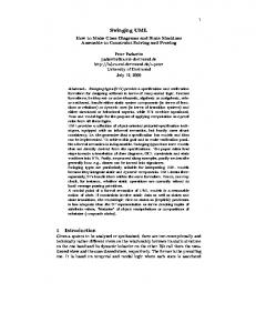
The concept of location plays an important role in the case of mobile systems. To denote classes whose instances are locations we use the stereotype location . For example, the airport Charles de Gaulle (CDG) is an instance of the stereotyped class Airport. Similar to the ambient calculus [4] we allow locations to be nested (cf. Fig. 2). For example, the airport Charles de Gaulle is contained in France, an instance of class Country, which is also a location. We require that any location is contained in at most one location and that a location cannot be contained in itself (directly or indirectly). We do not require that the hierarchy of locations has a single top element. Thus the hierarchy of locations forms a forest. Note that these assumptions, in particular the assumption that a location is contained in at most one location, simplifies the semantics and in consequence the analysis of mobile systems.
Country name
* has
Airport name origin
1 destination
*
*
Flight
Plane
type numberOfSeats land() takeOff()
1
run
*
number date boardingTime gate
*
Passenger name eat() board() deplane()
Fig. 2. A simplified class diagram modeling an airport.
3.2
Mobile Objects
A mobile object is an object that can change its location. A class representing mobile objects is indicated by the stereotype mobile . The current location of a mobile object is indicated by the atLoc relation. As in the case of locations, a mobile object can only be contained in at most one location. In our airport example, a particular passenger is a mobile object, as he may move from one location to another, for example, from Munich to Paris (cf. Fig. 2). Note that the atLoc relation is not explicitly presented in Fig. 2. One reason is that this would unduly complicate the diagram. For example, a passenger can be located either at a plane, an airport, or a country. The second reason is that the existence of the atLoc relation is implied by the use of the mobility stereotypes. Locations can be mobile too. This allows us to model passengers in an airplane and flying the airplane from one airport to another. In this case the stereotype mobile location is used. The stereotype mobile location inherits from the stereotype location and the stereotype mobile for mobile objects. This was the only way to define mobile locations by stereotypes with the UML 1.3, because a model element could have only one stereotype attached to it. However, from UML 1.4 on it is possible to attach more than one stereotype to a model element. In this case we could give the class Airplane the stereotypes mobile and location to denote that it is a mobile location. However, we feel that using the stereotype mobile location conveys better the concept of mobile locations. For mobile locations we require that the atLoc relation inherited from mobile objects is the same as the atLoc relation inherited from locations. To ensure this, stereotypes mobile and location inherit from a common stereotype spatial which denotes classes of objects that can be at a location (cf. Fig. 3). Figure 3 shows the metamodel for the stereotypes location , mobile and mobile location . To model the atLoc relation, we require that each class with stereotype location or mobile provides its instances with an attribute atLoc. Since we want to state the requirement only once, we introduce the abstract stereotype spatial and state the requirement for that stereotype. Then the stereotypes location and mobile inherit the requirement. To express this as an OCLconstraint, we define an additional predicate isAtLocAttribute on features, i.e. instances of metaclass Feature. In the metamodel each class is associated with a set of features describing the methods and attributes of the class and its instances. A feature e is an atLoc attribute, i.e. isAtLocAttribute(e), if e is an instance attribute, has the name atLoc and its multiplicity is zero or one. Further, the attribute can hold instances of classes having stereotype location : isAtLocAttribute(e : Feature) = e.oclIsKindOf(Attribute) and e.name = ’atLoc’ and let e0 = e.oclAsType(Attribute) in
e0 .ownerScope = #instance and e0 .multiplicity = 0..1 and e0 .targetScope = #instance and e0 .type.oclIsKindOf(Class) and e0 .type.stereotype.name->includes(’location’) Now we require that each class with stereotype spatial has a unique atLoc attribute and that the atLoc relation does not contain cycles: self.allFeatures->select(e | isAtLocAttribute(e))->size() = 1 and self.allInstances->forAll(o | o.parentLocs->excludes(o)) The additional operation parentLocs computes the set of all parent locations for an instance of a class with stereotype spatial : self.parentLocs = self.atLoc->union(self.atLoc.parentLocs) For mobile objects we require in addition that they are able to change their location, which means that their atLoc attribute can change its value. This can be expressed by requiring that the changeability attribute of atLoc has the value #changeable for all classes with stereotype mobile , in addition to the existence of an atLoc attribute — which is inherited from stereotype spatial : self.allFeatures->forAll(e | isAtLocAttribute(e) implies e.oclAsType(Attribute).changeability = #changeable) The operation allFeatures is an additional operation on Classifier defined in the UML 1.5 semantics. It collects the features of a classifier together with all features of its parents.
4
Sequence Diagrams for Mobility
In this section we study the use of Sequence Diagrams for modelling mobile systems. We show that the standard form of UML Sequence Diagrams can be hardly used for modelling of mobile systems. We present therefore a new notation, the so called Sequence Diagrams for Mobility [12]. SDM models mobile, nested and dynamically changing structure by generalizing the concept of object lifeline of UML sequence diagrams. This idea generalizes the idea of Use Case Maps [3] and allows us to specify mobile objects with nested structure. 4.1
Modeling with standard UML Sequence Diagrams
In this subsection we consider modelling of mobile systems with standard UML Sequence Diagrams. ps
ap
[atLoc = MUC]
board()
[atLoc = MUC]
ps [atLoc = ap]
notice() notice()
fly()
ap
[atLoc = CDG]
deplane()
ps [atLoc = CDG]
Fig. 4. Boarding, flying and deplaning.
Let us model a passenger ps who boards an airplane ap at Munich M U C airport, flies to Paris Charles De Gaulle CDG and then deplanes (cf. Fig. 4). It is not easy to model this using sequence diagrams only, since there exist no direct means for modelling change of state nor change of topology (for example the fact that a passenger is in airport and then in a airplane). The state description can be contained in the box; the fact that the person is at Paris airport is indicated by [atLoc = CDG:Airport]. This kind of modelling has the disadvantage, that when an object changes its state, we need a new box. Such boxes can be connected by a message arrow with stereotype become . Let us observe that boarding an airplane involves an airplane and a passenger, but here boarding is modelled indirectly as the change of state of a passenger. To disallow a plane to fly without a passenger we need notice() message to ‘inform’ the plane that the passenger boarded.
As we see, UML sequence diagrams can model mobility in an indirect way and even in this simple example the diagram is rather hard to read. There are also other possibilities to model this using standard UML Sequence Diagrams but they do not yield readable specifications either. Therefore, in the following we introduce a new kind of sequence diagrams which are better suited for modelling mobility. 4.2
Sequence Diagrams for Mobility: Basic concepts
In this subsection we present the basics of Sequence Diagrams for Mobility, an extension to UML Sequence Diagrams for modelling mobile systems. We show how to model artifacts like crossing barriers or communication. Like in Maude [6] a mobile object can migrate from one host to another , it can be also a host for other mobile objects. It may interact with other objects. Like a location, a mobile object can host other mobile objects, it can locally communicate and receive messages from other places. Objects can be arbitrarily nested, generalizing the limited place-agent nesting of most agent and place languages. In the ambient calculus [4] communication across a single barrier is synchronous; communication across multiple barriers is performed via other ambients which navigate from one location to another. In UML but also in Maude, objects can communicate in synchronous or asynchronous way. We stick to this principle. Unlike ambients, in our notation it is possible to express actions at a distance (like RMI) even if many barriers are involved, so that multiple steps can be rendered atomic. In general, we do not want to restrict the language artificially; if something is easy to specify in our notation, then we allow it without bothering whether it is easy to implement or not. But of course, if necessary one can define a dialect disallowing some expressions. ps
c
ap
d : MO
ps
Fig. 5. Object mobility.
A mobile object can change its location performing a move action. For example, a passenger may enter an airplane and then leave it; in this case the topology changes too (cf. lhs. of Fig. 5). A virus may cross a firewall in a message (cf. rhs. of Fig. 5). To model this, the object lifeline in sequence diagrams is blown up to an action box; it models actions performed by a mobile object and indicates the boundaries of the object. Consequently, in our two dimensional representation we have two lines which denote the same thread. This implies that different arrows must be attached to different levels of an action box.
A description of a mobile object’s behavior starts with a box containing optionally the object name or class. A mobile object may move into another object, or move out of an object. If an object moves into or out of another object, then the action box ends in the former location and the object is moved to another location. This move action is indicated by a stereotyped message arrow which starts with a black circle; we call it move arrow. We use here a notation similar to UML state machines to indicate that after the move the moving object starts its operation in a new location. A mobile object can not continue its operation outside of its new host, if it is already inside another host; consequently the arrow starts strictly at the end of the first action box to indicate that all other actions in the box must precede the move. We assume, that the mobile objects can not be bi-located or merged, therefore an object box may have at most one move arrow attached to the top and at most one arrow attached to the bottom. If a mobile object starts its operation (and was not active before anywhere else), then this is indicated by a special box like in the case of sequence diagrams. If a mobile object was already active somewhere else, then there must exist a move arrow such that its sharp end is attached to the left or right upper corner of the corresponding action box. This requirement corresponds to the fact that mobile objects can not be merged, nor appear out of nowhere. An action box of an object which already performed a move may optionally start with the objects name and/or class. We indicate the end of mobile object description by two horizontal lines, where the upper line is dashed. Figure 5 shows what a mobile object looks like. As in the case of sequence diagrams, the object’s names must be underlined. In the left hand side of the figure, a passenger ps enters airplane ap. Since there is no conflict concerning the identity of objects inside ap, the corresponding action box does not bear any name. Then ps deplanes ap and starts its operation outside ap. The name in the action box is not necessary either, since the identity of ps can be uniquely traced. No message arrow is attached to the corresponding action box except of the move. The right hand side of Fig. 5 shows a mobile object c entering object d of class M O by activating an operation of d (like a virus which sends itself in an e-mail). After the operation is finished the objects starts to operate inside d.
131 : PC virus
b : MO
c
742 : PC
virus
Fig. 6. Object creation and copying.
The left hand side of Fig. 6 shows the creation of a new object. The right hand side of this figure shows a proliferating virus. This virus starts a procedure on another PC to enter it. We use a message with stereotype copy [13], the copy is then assumed to behave as its original would do inside the new location. a
b : MO b2 b1 m n k
Fig. 7. Opening an object.
Another important operation is open (cf. Fig. 7), this operation opens an object making its hosted objects visible. If a mobile object is opened, then it ends its life, but its sub-objects continue to operate. This operation is similar to operation open in the ambient calculus [4], but it may be synchronous as well as asynchronous, depending on the type of message used. The opening of an object is indicated by a horizontal line. Object a sends message open to b, then object b is opened and the hosted objects b1 and b2 continue to operate. A mobile object can be also terminated, in this case all its hosted objects are terminated too, it can be of course expressed by a series of open operations. The recursive termination is indicated by a continuous line. For the recursive termination caused by an other object we use a message with stereotype destroy (cf. Fig. 8) (cf. [4]). In Fig. 8, object a terminates object b. After terminating b, all its sub-objects are terminated too. The termination is indicated by a continuous line stretching across all objects. a
b : MO b2 b1 m n
Fig. 8. Destroy.
4.3
Abstraction
In this subsection we present the zoom facility allowing one to abstract from the internal details or, vice versa, to show them. Abstraction is one of the most
important concepts to manage complexity. In the case of Sequence Diagrams for Mobility we can abstract from internal object details like the behavior of hosted objects, behavior of an object during move actions and so on, or display them, depending on the desired level of detail. 131 : PC
742 : PC
131 : PC
742 : PC
virus
Fig. 9. Zoom-out.
The left hand side of Fig. 9 shows the virus attack (cf. Fig. 6), in the zoomout view, as perceived by the user of the attacked PC. He/she can usually not look inside the PC hosting the virus. For an external observer who can only see the communication network, the whole situation may look like the right hand side of the figure. It is possible to zoom into an object’s move arrow to see the behavior of the participating objects. Figure 10 shows flight from Munich to Paris in a zoom-out view. The details of the flight can be seen on Fig. 10. 4.4
Example
In this subsection we consider a person flying from Munich to Paris. Figure 10 shows a simple story of a passenger x1 who boards an airplane in Munich airport, flies to Paris and publishes a picture in a WAN. This story is described from the perspective of an observer on the German side. The person x1 together with other passengers enters the airport and then boards the airplane LH123. The airplane flies to Paris (the flight number is 99), but the only thing the observer can see is that the airplane is airborne but not what happens inside the airplane nor further details of this flight. The next event which the observer is able to notice is the appearance of a picture in the WAN. To model several passengers (i.e. objects of class Passenger), we use the multi-object notation [13], which allows us to present in a compact way several passengers playing the same role. Person x1 is distinguished using composition relationship. This simple view shows some of the barriers person x1 has to cross while flying. There are political boundaries which regulate the movement of people and devices, like airplanes, computers and so on. Within those boundaries, there are other boundaries like those protecting airports and single airplanes against intruders. We specify explicitely such boundaries and the moves across them. In
F
D MUC : Pass x x1
LH123:Plane
flight99 :WAN
picture
Fig. 10. Flight example.
the view presented in Fig. 10, we have abstracted from several details. The view of passenger x1 is much more detailed (cf. Fig. 11).
D F
MUC LH123:Plane
: Pass
x1
flight99
CDG
LH123 x1
:WAN
nb
dc p
: Pass x x1
Fig. 11. Flight’s details.
We can see what happens inside the airplane during the flight; the move arrow contains the action box of the airplane LH123. Passenger x1 makes pictures with his digital camera; the pictures are send then to the WAN. As usual, a digital camera does not allows him to send pictures directly to the WAN. It is also forbidden to use mobile phones during the flight. Therefore the passenger saves the pictures to his notebook nb, logs into the on-board network and then transmits the pictures to WAN via the on-board network. We abstract here from the structure of the WAN network (indicated by dashed line). Let us point out
that the sending of the picture by passenger x1 is not temporally related to crossing any border like those over D, EU and so on. The only thing we can say is that it happens between the start of the airplane and its landing. Finally, all the passengers leave the airplane and the airport. The passenger can see that the airplane is boarded by new passengers. The dashed line in the head of the last box of passenger x1 means that the history of this passenger started earlier and that the head of the object box is not beginning of its lifeline, but a continuation.
5
Modeling with Activity Diagrams
In this section we introduce two variants of activity diagrams for modeling mobility. These diagrams were introduced in [2]. The first variant is responsibility centered and uses swimlanes to model who is responsible for an action. The second is location centered and uses the notation of composite objects to visualize the hierarchy of locations. Basically, there are two primitives that change the location of a mobile object. A mobile object can move from one location to another — a so called move action; or a copy of an object is moved to a new location [7] — a so called clone action. These actions act on objects and their containment relationship wrt. locations. Given a move action on an object o which is contained in location l, i.e. o.atLoc = l, to another location l0 , then after performing the move operation object o is contained in location l0 , i.e. o.atLoc = l0 . Operation clone works similar; however, instead of moving the object itself, first a copy of the object is created which is then moved to the new location. The stereotypes move and clone for action states in activity diagrams are used to denote move actions and clone actions, respectively. Actions have two additional attributes, the first one indicates who is performing the action, and the second one is the location where the action is performed. Calculi for mobility restrict these primitives further by omitting the clone operation. Instead, the clone operation is defined as the composition of a copy operation followed by a move action. For notational convenience we decide to take clone as a primitive. Commonly, these calculi also restrict the target location of a move, for example, to move only one level in the containment hierarchy [4, 14]. In the following, we present two notations for the above mentioned mobility concepts in the context of activity diagrams. The first notation is responsibility centered and focuses on who is performing an action and is based on the standard notation for activity diagrams. The second notation is location centered and focuses on where an action is performed, given by the atLoc relation between mobile objects and locations, and how activities change this relation. 5.1
Responsibility Centered View
The first notation uses object-flow states with classifier in states to model the atLoc relation. In the airport example consider a passenger Hubert who is boarding a plane at the airport of Munich. This can be modeled as a move action
as shown in Fig. 12. The source of the move action is the object-flow state Hubert:Passenger [atLoc = MUC:Airport] and the target an object-flow state Hubert:Passenger [atLoc = LH123:Plane]. The passenger Hubert moves from his previous location, Munich airport (M U C), to his new location, the plane LH123. More precisely this means, if in an object configuration there is a passenger Hubert, an airplane LH123 and an airport M U C such that Hubert is contained in M U C and also LH123 is contained in M U C, the move operation changes the configuration in such a way that Hubert is no longer directly contained in the airport M U C, instead it is contained in the plane LH123. The containment of the plane does not change; therefore Hubert is still indirectly contained in M U C. Swimlanes can be used to show who is performing the action; in this case it is the passenger who boards the plane.
Hubert
Hubert : Passenger [atLoc=MUC]
boarding
Hubert : Passenger [atLoc=LH123]
Fig. 12. The move action.
The clone operation is shown in Fig. 13 for a list of passengers (lop). One copy of the list is kept by the airport staff and another copy of the list is moved into the plane. The difference in the semantics of this diagram to the previous diagram is that given the configuration as before, the clone operations creates a new document list of passengers lop0 which differs from lop only in the fact that it is contained in LH123. In addition lop is still contained in M U C, i.e. lop has not moved at all. Note that by the UML it is possible to omit the become stereotype in the output of the move action in Fig. 12, as it is the default that the input and the output are the same objects if the type of the object flow states are the same. In the same way, the copy stereotype in the output of the clone action in Fig. 13 can be omitted because this stereotype can be deduced from the stereotype clone of the clone action. A more complex example is given in Fig. 14. The activity diagram starts with the boarding activity of the passenger at the Munich airport. This activity changes the location of the passenger Hubert from the airport (M U C) to the particular plane LH123. The next activity is the take-off activity of the plane.
lop : Document [atLoc=MUC]
take on board
lop’ : Document [atLoc=LH123]
Fig. 13. The clone action.
This activity changes the location of the plane from the Munich airport (MUC) to a not specified destination, that is we are not interested in the location where the plane is when it is flying. During the flight, the plane performs the flying activity and the passenger the send mail activity. These activities happen in parallel. Note that before landing, the passenger has to stop the send mail activity because the use of electronic devices is not allowed during take-off and landing. When landing, the location of the plane is changed to the destination airport, in this case the Paris airport (CDG). Finally, the passenger deplanes and is now located at the Paris airport. This notation is responsibility centered as the swimlanes are indicating who is performing a particular activity.
Hubert
LH123 LH123 [atLoc=MUC]
Hubert
[atLoc=Muc]
boarding
take off
Hubert [atLoc=LH123]
LH123
send mail
Hubert [atLoc=CDG]
deplaning
flying
landing
LH123 [atLoc=CDG]
Fig. 14. The airport example using the responsibility centered notation.
5.2
Location Centered View
MUC:Airport Hubert:Passenger LH123:Plane
boarding
Hubert:Passenger
Fig. 15. The move action.
The second notation uses containment of the boxes for mobile objects/locations in the boxes of other locations to show the atLoc relation. For that we use the same UML notation as for composite objects. A difference is that the atLoc relation is not an aggregation. Another difference is that we also allow action states to be drawn inside composite objects of stereotype location . This indicates that the action is performed at the corresponding location. Figure 15 shows this notation for the move operation depicted in Fig. 12. Note, that in addition to the fact that the passenger is in the plane, we can model also that the plane is parked at the airport. This is an information that cannot be represented in the responsibility centered approach as shown in Fig. 12. What Fig. 15 also shows is that activities can be drawn inside locations to indicate that the operation is performed at that location. In the example, boarding takes place at the airport. While it is still possible to use swimlanes to indicate who is performing an action, most likely, more complex diagrams will have to concentrate on either the topology of locations or on the actor performing an activity to avoid an overloaded diagram. Note that the box containing the airport may be omitted if this is not relevant for the presentation. Figure 16 presents a location centered view of the activities of Fig. 14. Again, the first activity changes the location of the passenger from the airport to the plane. However, in contrast to the responsibility centered notation it is visible that the passenger is still located indirectly in the Munich airport, because the plane has not moved yet. Also one can see that the boarding activity happens at the airport. The next activity, the take-off, takes again place at the airport. In the location centered variant the notation indicates that the plane has left the airport after take-off. Again, during the flight the activities flying and send mail happen in parallel. In contrast to the information provided by the responsibilitycentered notation, this notation shows that the send mail activity happens in the
plane, while flying does not take place inside the plane. Note that for simplicity reasons, the box denoting the passenger during the flight can be omitted. Landing and deplaning are similar to the activities boarding and take-off.
6
Security
There is a very wide range of security requirements and design features which, ultimately, we would like to be able to record in our variant of UML and analyse with formal tools [5]. Much of this is outside the scope of formal techniques, for example because it pertains to information that is legal, psychological or sociological rather than mathematical. Nevertheless we do not wish to limit our UML profile to expressing only the characteristics that the tools can analyse. Our main source for security features is a profile UMLsec developed by Jan J¨ urjens [10, 9]. The most detailed source of information is his PhD thesis Principles for Secure System Development [9]. His fifth chapter, entitled Secure Systems Development with UML, defines the profile. (Note that the thesis also includes a formal semantics based on ASMs for a restricted fragment of UML. We do not adopt the semantics, since it is not suitable for our tool support and the fragment of UML is not appropriate to our needs. However, the profile itself does not depend on the formal semantics, so adopting the profile but not the semantics is reasonable.) We do not reproduce UMLsec’s definition here, but to give an overview of its capabilities we first quote J¨ urjens’ list of requirements on the profile, and then give an example, also taken from [9].
MUC : Airport
CDG : Airport
flying
Hubert
boarding
LH123 : Plane
LH123 : Plane
landing
Hubert
Hubert
deplaning
Hubert LH123 : Plane send mail
Hubert
take off
Fig. 16. The airport example using the location centered notation.
6.1
Requirements on UMLsec
Security requirements One needs to be able to formulate basic security requirements such as secrecy and integrity of data in a precise way. Formalizations of basic security requirements are provided via stereotypes, such as secrecy and integrity . Threat scenarios It should be possible to consider various situations that give rise to different possibilities of attacks. Threat scenarios are incorporated using the formal semantics and depending on the modelled underlying physical layer via the sets of actions available to the adversary of a particular kind. Security concepts One should be able to employ important security concepts (for example that of tamper-resistant hardware). To incorporate security concepts such as tamper-resistant hardware, threat scenarios can be used. Security mechanisms One needs to be able to incorporate security mechanisms such as control access. For example, modeling the Java security architecture access control mechanisms. Security primitives On a more fine-grained level, one needs to model security primitives. They are either built in (such as symmetric and asymmetric encryption), or can be treated (such as security protocols). Underlying physical security It is necessary to take into account the level of security provided by the underlying physical layer. This can be addressed by the stereotype secure link in deployment diagrams. Security management Security management questions (such as secure workflow) need to be addressed. This can be considered by using activity diagrams.
6.2
Example of UMLsec
Figure 17 shows an example concerning communication link security which can be used in our airport case study for describing the login of a passenger into a network. The client workstation and the server are linked via a communication link; here a stereotype internet shows that the link is of a specific kind (the Internet). There is also a dashed-arrow dependency going from the web server to the client through the client application’s interface. The component web server uses the services of the component client apps. The stereotype secrecy is used to indicate the precise dependency between the two.
:ClientMachine
:ServerMachine get_password
client apps browser
web server
access control
Fig. 17. Secure links usage
6.3
Global computing requirements beyond UMLsec
Although UMLsec is a good basis for the security aspects of our profile, it does not completely meet all requirements for global computing. In particular, we have to extend UMLsec by stereotypes for messages in sequence diagrams to represent requirements on the communication medium to be used for that particular message. For example, we have to be able to represent by a stereotype secure , that a particular message is communicated via a secure medium. Figure 18 gives an overview of our security related stereotypes.
7
Performance
Performance requires more sophisticated extensions to UML than in many other areas. The OMG’s standard profile for Schedulability, Performance and Time [15] meets quite closely what performance modellers are looking for. There are some areas where changes are needed and many open questions which can only be answered by further practical experience within the project, which is ongoing at the time of writing. 7.1
Introduction to the performance aspects of [15]
One of the reasons why a performance profile is more complex than a security or mobility profile is that it needs to support a variety of related, but different, aims. The performance modeller does not simply record information about performance requirements that must be taken into consideration, or perhaps verified. Several different kinds of information must be recorded: requirements, measured performance, performance assumptions and performance predictions, for example. Some of this information will be output from a performance analysis or simulation tool; other parts of the information will be input to such tools,
> message
>
>
> protocol
> wireless−protocol
> wireless
> MMS
>
> secure
> secure−wireless
Fig. 18. Security added stereotypes
used in various ways. The profile must support the user in recording all these kinds of information and in differentiating between them. Quoting from [15] p135: The profile provides facilities for: – Capturing performance requirements within the design context – Associating performance-related QoS characteristics with selected elements of a UML model – Specifying execution parameters which can be used by modeling tools to compute predicted performance characteristics – Presenting performance results computed by modeling tools or found in testing Typical tools for this kind of analysis provide two important functions. The first is to estimate the performance of a system instance, using some kind of model. The second function is assistance with determining how the system can be improved, by identifying bottlenecks or critical resources. A system designer will typically want to analyse the system under several scenarios using different parameter values for each scenario while maintaining the same overall system structure.
Providing UML extensions that allow designers to do these tasks using any one of a number of different analysis techniques is challenging. The authors of [15] have separated two tasks. First, they have designed an extensible collection of abstract modelling concepts to describe the information necessary for performance (and more generally, schedulabilty and real time) analysis. Their collection is layered for manageability. The most abstract level is the general resource model describing the relationships between a range of basic analysis concepts, such as resource and various quality of service attributes. Several packages, including the performance modelling package which is our concern, extend this basic model. There is the possibility of extending the model further for global systems specific purposes, though we have not so far felt the need to do so. An analysis technique is defined in terms of the concepts, and can then apply to any notation, graphical or otherwise, from which the information embodied in the “concepts” can be derived. Second, [15] provides a collection of UML stereotypes (i.e. specialised versions of UML model elements) and mappings from these to the concepts. This allows the relevant performance information to be expressed in a UML model. The information is then mapped to the “concepts”, and so an analysis technique defined in terms of the concepts can be applied. The whole process of applying an analysis technique to a UML model can be automated. It is not practical or useful to attempt to reproduce here all the facilities provided by [15]; instead we give examples and refer the interested reader to [15] for fuller information. One of the fundamental concepts for the underlying performance model is a step. Several different kinds of UML model element (Message, Stimulus, Action State and Subactivity State) may be used to represent a step. Each of them may be labelled with the stereotype PAstep to indicate that a performance model should include a step corresponding to this model element. The stereotype PAstep has seven tags: PAdemand, PArespTime, PAprob, PArep, PAdelay, PAextOp, PAinterval. The three tags used in our example are:
– PAdemand is the total execution demand of the step on its host resource. Every scenario step in Fig. 19 has a PAdemand tagged value indicating its estimated mean execution time on the host processor. – PAextOp is used to specify the set of operations of resources used in the execution of a step but not explicitly represented in the model. Each operation attribute identifies the operation and the number of times it is repeated. – PAprob is the probability, in situations where its predecessor step has multiple successors, that this step will be executed. Figures 19 and 20 show examples of the use of the stereotype and these tags. Figure 19 means that here our tagged value expression represents a demand in the scenario step with an estimated mean value of 0.2 milliseconds. It calls an external operation called ’network’, ’P’ times.
{PAdemand= (’est’, ’mean’, 0.9, ’ms’), PAprob=0.2} get private document
get document from buffer
get public document
Fig. 20. Probability
In Fig. 20 when the request is accepted, there is a probability of 0.5 that the document will be read from the buffer, 0.2 from the disk containing the private documents, 0.3 from the disk containing the public documents. Our last example, Fig. 21, illustrates the use of nodes. Here the ClientWorkstation is a host processor. The stereotype PAhost has seven tags: PAschdPolicy, PArate, PAutilisation, PActxtSwT, PAprioRange, PApreemptable, PAthroughput. The four tags used in our example are: – PAschdPolicy is the access control policy for handling requests from scenario steps. The scheduling policy offers a choice of six tag types : here PR means Priority Inheritance. – PArate is a relative speed factor for the processor expressed as a percentage of some normative processor. – PAutilisation is the mean number of concurrent users of the resource. – PActxtSwT is the length of time (overhead) required by the processing resource to switch from the execution of one scenario to a different one. Here the estimated mean value is 40 microseconds.
In this paper we have presented extensions to UML sequence and activity diagrams to model the mobility aspects of global systems. We have also discussed how UML may be extended to model the performance and security aspects of global systems. We have defined stereotyped classes to model locations and mobile objects, as well as stereotyped action states to model move and clone actions. To model complex systems it is desirable to have the concepts for expressing mobility as part of the language — as we have done in this paper — instead of modeling these defining these concepts indirectly using special encoding. The new form of Sequence and Activity Diagrams provide a powerful graphical notation for modelling mobility. They allow one to model in a clear way complex behavior. For example, a formal specification of the flying person would be rather very complicated, but a graphical representation would make it much easier to understand. Within the two projects primarily concerned with this work, AGILE and DEGAS, work is proceeding as follows. Within AGILE, we are currently investigating the appropriateness of UML for the specification of structural and behavioral aspects of mobile systems. Our next step will be to validate the proposed notations in a bigger case study. The objective of AGILE is to develop an architectural approach in which mobility aspects can be modeled explicitly. Within DEGAS, we are connecting standard UML tools with a variety of formally based tools which are capable of performance and security analysis. We plan to develop a formal semantics for the extended activity and sequence diagrams to provide a precise meaning of the presented concepts which is needed for formal analysis and reasoning about models. In addition, we plan to develop tools that support animation, early prototyping and analysis of mobile systems.
References 1. AGILE. Architectures for mobility. www.pst.informatik.uni-muenchen.de, 2003. 2. Hubert Baumeister, Nora Koch, Piotr Kosiuczenko, and Martin Wirsing. Extending activity diagrams to model mobile systems. In M. Aksit, M. Mezini, and R. Unland, editors, Objects, Components, Architectures, Services, and Applications for a Networked World, LNCS 2591, pages 278–293, Berlin-Heidelberg, October 2002. Springer-Verlag. 3. Raymond Buhr and Ronald Casselman. Use Case Maps for Object-Oriented Systems. Prentice-Hall, USA, 1995. 4. Luca Cardelli and Andrew Gordon. Mobile ambients. In Maurice Nivat, editor, First Conference on Foundations of Software Science and Computation Structure, LNCS 1378, pages 140–155. Springer Verlag, March 1998. 5. DEGAS. Design Environments for Global Applications. www.omnys.it/degas. 6. Francisco Dur´ an, Steven Eker, Patrick Lincoln, and Jos´e Meseguer. Principles of Mobile Maude. In David Kotz and Friedemann Mattern, editors, Agent Systems, Mobile Agents, and Applications, Second International Symposium on Agent Systems and Applications and Fourth International Symposium on Mobile Agents, ASA/MA 2000, LNCS 1882, pages 73–85. Springer, 2000. 7. FIPA. FIPA agent management: Support for mobility specification. www.fipa.org, August 2001. 8. Jin Jing, Abdelsalam Helal, and Ahmed Elmagarmid. Client-server computing in mobile environments. ACM Computing Surveys, 31(2):117–157, 1999. 9. Jan J¨ urjens. Principles for Secure System Development (submitted draft). PhD thesis, University of Oxford, UK, 2002. 10. Jan J¨ urjens. UMLsec: Extending UML for secure systems development. In In proceedings of UML2002, LNCS. Springer, 2002. 11. Cornel Klein, Andreas Rausch, Marc Sihling, and Zhaojun Wen. Extension of the Unified Modeling Language for mobile agents. In K. Siau and T. Halpin, editors, Unified Modeling Language: Systems Analysis, Design and Development Issues, chapter VIII. Idea Group Publishing, Hershey, PA and London, 2001. 12. Piotr Kosiuczenko. Sequence diagrams for mobility. In Stefano Spaccapietra, editor, 21 International Conference on Conceptual Modeling (ER2002). SpringerVerlag, October 2002. to appear. 13. OMG. Unified Modeling Language (UML), version 1.5. www.omg.org, March 2005. 14. Dirk Pattinson and Martin Wirsing. Making components move: A separation of concerns approach. In Proc. First Internat. Symposium on Formal Methods for Components and Objects, FMCO’02, Leiden, November 2002, LNCS, 2003. To appear. 15. Bran Selic, Alan Moore, Murray Woodside, Ben Watson, Morgan Bjorkander, Mark Gerhardt, and PDorina Petriu. Response to the OMG RFP for Schedulability, Performance, and Time, revised, June 2001. OMG document number: ad/200106-14. 16. Axel Wienberg, Florian Matthes, and Marko Boger. Modeling dynamic software components in UML. In Robert France and Bernhard Rumpe, editors, UML’99 The Unified Modeling Language. Proceedings, LNCS 1723, pages 204–219. SpringerVerlag, 1999.