May 5, 2011 - language can be used in any general-purpose UML modelling tool and ... computer interaction) standard of a business application that defines ... program code at all but to application repository data instead, if a data-driven.
DOI: 10.2298/CSIS110112010P
UML Profile for Specifying User Interfaces of Business Applications Branko Periˇsi´c, Gordana Milosavljevi´c, Igor Dejanovi´c, and Branko Milosavljevi´c University of Novi Sad Faculty of Technical Sciences {perisic,grist,igord,mbranko}@uns.ac.rs
Abstract. This paper presents an approach to automatic user interface code generation that is based on our own HCI standard that defines layout and behaviour of coarse-grained objects for enterprise business applications. A domain-specific language (in the form of a UML profile) based on the concepts introduced by the HCI standard facilitates efficient modeling and generation of fully-functional UIs. Being a regular UML extension, this language can be used in any general-purpose UML modelling tool and can easily be integrated with other UML-based models of the application. Key words: user interface, code generation, MDA, UML profile
1.
Introduction
Various aspects of model-based development of user interfaces (UIs) are the subject of intensive research efforts. However, the majority of presented solutions is hardly applicable to development of real-world information systems because too much time and effort is spent on developing and synchronising different types of user interface models (for example, presentation model, content model, navigation model, interaction model), the complexity of sharing the knowledge embedded in different models, the lack of support in development tools, and the lack of consensus over which types of models best describe UIs [23]. Most tools for modelling user interfaces use its own set of notations, thus impeding the integration with other application models [26]. This is especially the problem in developing business applications that require tight integration of UI models with models that specify business logic. In order to overcome the problem of integration and to facilitate the exchange of information among different tools, UML can be used to model all aspects of an application, including the user interface [3]. Although very powerful, UML without extensions is not suitable for modelling UIs [26, 3, 19]. This paper presents a UML extension in the form of a UML profile for specifying UIs of business applications named EUIS (Enterprise User Interface Specification profile). EUIS is developed in order to enable rapid user interface mod-
B. Periˇsi´c et al.
elling at a high level of abstraction. EUIS is based on our own HCI (humancomputer interaction) standard of a business application that defines functional and presentational features of coarse-grained building blocks thus enabling the generation of a fully functional UI, without the need for defining a multitude of models used for developing UIs in the general case. It is important to note that the UI model is not a model of an application (from the implementation standpoint); it defines the structure of the application using building blocks at a high abstraction level (different types of screen forms, reports, procedures) and their relationships. Depending on the development platform, the intended application architecture, and the implementation of a code generator, one class from the UI model may be mapped to one or more classes or modules of an application, or may even be not mapped to the program code at all but to application repository data instead, if a data-driven application architecture is used (for example, see [13, 14]).
PIM Problem domain model
PSM Database model Middleware / Business logic model User interface model
Generated Database scripts
Middleware
User interface
Application elements meta-data «import»
Application repository
Fig. 1. Model transformations
The development of a whole business application using the EUIS profile comprises the following activities (see Figure 1): – The development of PIM (platform independent model) of a problem domain by means of class diagrams in a general-purpose UML modelling tool. – The automatic transformation of a PIM to PSMs (platform-specific model): database schema model, user interface model, and the middle-tier model (in the case a three-tier architecture is chosen). – Automatic generation of artifacts needed for implementation based on PSMs: database schema creation or alteration scripts, middle-tier implementation artifacts (such as EJBs), fully functional application UI (depending on the target architecture of the client application), and atomic “CRUD” transactions implementing creation, retrieval, update, and deletion for every entity in the persistence layer.
406
ComSIS Vol. 8, No. 2, Special Issue, May 2011
UML Profile for Specifying User Interfaces of Business Applications
The rest of the paper is structured as follows. Section 2 describes the basics of the HCI standard. Section 3 presents the EUIS profile. Section 4 reviews the related work. The last section concludes the paper.
2.
The HCI Standard
Our human-computer interaction (HCI) standard is aimed at defining functional and visual features of course-grained application components. Its goals include the following: simplicity of use, quick user training, and the automation of user interface construction. The papers [16, 17] define a number of types of screen forms. For this discussion, the following types are relevant: – – – –
standard data management form, standard panel, parent-child form, and many-to-many form.
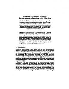
Standard form is designed to display data and all available operations so the user can choose a data item and invoke an operation on it without memorising commands (the object-action approach [24]). Standard operations common to all entities are represented by buttons/icons at the top of the form, while specific operations (if they exist) are represented by links/buttons at the right hand side. The standard form layout is presented in Figure 2.
Title
Form header
…
Specific operations and next forms
Standard operations toolbar
Data display area
Fig. 2. Standard form layout
Operations common to all entities include search (query by form), display, addition, update, removal, copying, data navigation and view mode toggle (grid view or single record view). Specific operations include complex data processing procedures associated with the given entity (transactions), invocation of related (next) screen forms, and invocation of reports. The standard mandates that the specific operations always use the currently selected (viewed) record.
ComSIS Vol. 8, No. 2, Special Issue, May 2011
407
B. Periˇsi´c et al.
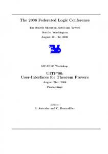
Standard panel has the appearance and the behaviour of the standard form but, instead being shown in its own window, it is used as an element of a complex form. Standard panels are regularly used for parent-child and many-tomany forms. A parent-child form is used for data that have hierarchical structure, where each element in the hierarchy is modelled as an entity in the persistence layer. Each element in the hierarchy is represented by a standard panel, where a panel at the n-th hierarchy level filters its content according to the selected data item at the level n − 1. The many-to-many form is used for intensive management of data belonging to entities connected by “many-to-many” relationships, with or without associate classes. Its layout is presented in Figure 3. This screen form is used as follows: – A number of desired records are selected in the upper panel. These records are “dragged” to the lower panel by clicking the button with the downwards arrow. If a record is dragged by mistake, it can be revoked back by clicking the upwards arrow button. – The values of non-key attributes of a record selected in the lower panel may be changed.
Form header
Title
Panel for choosing records Downwards arrow and upwards arrow buttons
Panel for chosen records
Buttons for specific operations
Fig. 3. Many-to-many form layout
Relationships among screen forms are represented by three mechanisms: zoom, next, and activate. The zoom mechanism represents the invocation of the form associated with the given entity where the user can choose a data item and “drag” it (pick its values) to the fields of the previously viewed form. The next mechanism, invoked from the form associated with the current entity, displays the form associated with the child entity with its data filtered so that only connected objects are displayed. The key or a representation of the parent entity is displayed in the form header, so the user easily recognises the current context. A next can be invoked by menu items, buttons, or links.
408
ComSIS Vol. 8, No. 2, Special Issue, May 2011
UML Profile for Specifying User Interfaces of Business Applications
The activate mechanism enables direct invocation of a form by another form, without restrictions on the data displayed. The invoked form does not need to be related to the current one.
3.
The EUIS Profile
The EUIS profile extends the following metaclasses from the UML::Kernel package: Element, Class, Property, Operation, Parameter, Constraint, and Package. It is complementary to the profile for modelling persistent data that is available in a majority of modelling tools (see Figure 4). Therefore, EUIS is independent on modelling tools, persistence layer and the database of choice. Profile that models persistent data comprises only the stereotypes present in the majority of modelling tools (possibly under a different name): persistent class, persistent property, persistent data type, and persistent operations (methods implemented in the persistence layer) – see Figure 5. When using the EUIS profile, these stereotypes are replaced with concrete stereotypes of the chosen modelling tool.
Kernel «import»
EUISProfile
PersistenceProfile «import»
Fig. 4. Profile structure
«metaclass» Class
«metaclass» DataType
«stereotype» PersistentClass
«stereotype» PersistentDataType length : Integer [0..1] precision : Integer [0..1] persistentDataType 1
«metaclass» Property
«stereotype» PersistentProperty
«metaclass» Operation
«stereotype» PersistentOperation
identifier : Boolean [0..1] = false unique : Boolean [0..1] = false identity : Boolean [0..1] = false nullable : Boolean [0..1] = true *
Fig. 5. Persistence profile
In order to specify additional information needed for transforming a problem domain model to a user interface model, another profile is developed (see Fig-
ComSIS Vol. 8, No. 2, Special Issue, May 2011
409
B. Periˇsi´c et al.
ure 6) that provides the following: defining a set of one or more properties as a business key – the BusinessKey stereotype [4], designation of a method as a complex business procedure – the Transaction stereotype, and the designation of a method as a report – the Report stereotype.
«metaclass» Property
«stereotype» BusinessKey
«metaclass» Operation
«stereotype» BusinessOperation
«stereotype» Report
«stereotype» Transaction
Fig. 6. Profile used in the problem domain model
Stereotypes and enumerated types of the EUIS profile are organised in the following categories: – – – – – – – – –
a visible element: extension of Element metaclass visible classes (panels): extensions of Class metaclass visible properties: extensions of Property metaclass visible methods: extensions of Operation metaclass visible parameter: extension of Parameter metaclass a group of elements: extension of Property metaclass visible association ends: extensions of Property metaclass validators: extension of Constraint metaclass a business subsystem: extension of Package metaclass
Due to space constraints, the rest of the section presents only the most important stereotypes and tags. Formal OCL constraints are not presented. 3.1.
Visible Elements
Stereotype VisibleElement (see Figure 7) represents a model element that is mapped to a user interface element in the generated application. Since Element metaclass is a common superclass of all UML metaclasses, this facilitates the representation of all model elements with an UI component and a label, where applicable. The enumerated type ComponentType defines a set of available UI component types. The set of components is designed to be platform-independent. Mapping these values to particular UI components of the chosen development platform is performed in the application generator.
410
ComSIS Vol. 8, No. 2, Special Issue, May 2011
UML Profile for Specifying User Interfaces of Business Applications
«enumeration» ComponentType «metaclass» Element
«stereotype» VisibleElement label : String [0..1] visible : Boolean [1] = true component : ComponentType [0..1]
textField passwordField textArea column checkBox comboBox selectionList radioButton label image tabbedPane panel grid border menu menuItem button
Fig. 7. Visible element
3.2.
Visible Classes
Stereotype VisibleClass (see Figure 8) represents a class that is mapped to a panel (a regular or a tabulated panel) in the application UI. If a panel is associated to an empty window or a web page, it becomes a screen form that can be independently activated (opened). Stereotype VisibleClass is not abstract because of the possibility of modelling specific panels that are not comprised by the HCI standard, but still occur rarely enough that there is no need to extend the HCI standard with a new element.
«metaclass» Class
«stereotype» VisibleElement
StdPanelSettings defaultOperationMode : OperationMode [1] = viewMode defaultViewMode : ViewMode [1] = tableView confirmDelete : Boolean = true stayInAddMode : Boolean = true goToLastAdded : Boolean = true
«stereotype» VisibleClass modal : Boolean [1] = true
«stereotype» PersistentClass
StandardOperations
{incomplete, disjoint} PanelType
persistentClass 1 * «stereotype» StandardPanel
«stereotype» ParameterPanel
«stereotype» ContainerPanel
«stereotype» MainPanel
{incomplete, disjoint} ContainerKind
StandardOperations StdPanelSettings
«stereotype» ParentChild
«stereotype» ManyToMany
«stereotype» PanelGroup
DataSettings «enumeration» OperationMode addMode updateMode copyMode searchMode viewMode
«enumeration» ViewMode
add : Boolean [1] = true update : Boolean [1] = true copy : Boolean [1] = true delete : Boolean [1] = true search : Boolean [1] = true changeMode : Boolean [1] = true dataNavigation : Boolean [1] = true DataSettings dataFilter : String [0..1] sortBy * «stereotype» VisibleProperty
tableView inputPanelView
Fig. 8. Visible classes
ComSIS Vol. 8, No. 2, Special Issue, May 2011
411
B. Periˇsi´c et al.
The inherited tag label is used as a window title or a label that explains the purpose of the panel if displayed within a complex panel. Stereotype StandardPanel denotes that the given persistent class is associated with a standard panel whose layout and behaviour are defined by the HCI standard. The standard panel implements three interfaces: StandardOperations – operations defined by the HCI standard: add, update, copy, delete, search, change mode, navigate data; StdPanelSettings – settings that define panel’s runtime behaviour; and DataSettings – defines data filtering and sorting. Stereotype ParameterPanel represents a class that is mapped to a panel for entering parameters for a visible method (see VisibleOperation stereotype) that is invoked by a button or a menu item. Since the majority of parameter panels in an application is created implicitly, as a result of a visible method and its parameters, classes with this stereotype rarely occur. It can be used in situations where a user successively invokes a number of methods with the same set of parameter values. The ContainerPanel is an abstract stereotype that represents a complex panel that can contain other panels (simple or complex), as well as a number of properties and methods. It defines additional attributes, methods, and constraints for its descendants (ParentChild, ManyToMany, and PanelGroup). The layout and behaviour of ParentChild and ManyToMany panels is defined by the HCI standard, while their relationship to the contained panels is defined by hierarchical relationships (associations with ends having the Hierarchy stereotype). For details on associating panels, see section 3.7. The layout and behaviour of a PanelGroup is not defined by the HCI standard. It is used for modelling special-purpose complex panels. The class with a PanelGroup stereotype defines only the contained elements, while their relationship is implemented in application code. Classes with the MainPanel stereotype are used for modelling the main form of a business subsystem (see section 3.9). 3.3.
Visible Properties
Stereotype VisibleProperty (see Figure 9) is a property of a “visible” class and is mapped to a UI component contained in the panel associated to the class. Its tags provide customisation of appearance and behaviour of the UI component, or the table column in the case of tabular display of data (label, columnLabel, dataFormat, disabled), default values in the UI component (default, defaultValueGetter ), and automatic focus traversal (autoGo). Tag default contains an OCL expression that defines the initial value, while defaultValueGetter contains the reference to the method used for fetching the default value (in cases when OCL expression cannot be used). Tag representative indicates that the given property can be used to represent the whole class from the users’ point of view (for example, company name, first name + ” ” + last name). Aggregated represents an aggregated property, whose value is calculated using one of the aggregation functions (min, max, sum, avg, count) over the
412
ComSIS Vol. 8, No. 2, Special Issue, May 2011
UML Profile for Specifying User Interfaces of Business Applications
«stereotype» VisibleElement
«metaclass» Property
«enumeration» AggregateFunction
«stereotype» VisibleProperty
min max sum avg count
{incomplete, disjoint} PropertyType «stereotype» Aggregated
«stereotype» Calculated
function : AggregateFunction [1] selection : String [0..1]
expression : String [0..1]
aggregatingAttribute «stereotype» PersistentProperty
0..1
performsAggregation 0..1 performsCalculation «metaclass» Operation
0..1
«stereotype» PersistentProperty persistentProperty 1
«stereotype» Persistent
«stereotype» Lookup
1
«metaclass» Operation
defaultValueGetter *
columnLabel : String [0..1] displayFormat : String [0..1] representative : Boolean [1] = false autoGo : Boolean [1] = false disabled : Boolean [1] = false default : String [0..1]
lookupClass 0..1 «stereotype» VisibleClass +modal : Boolean [1] = true
«stereotype» Editable
«stereotype» AutoDuplicate
* {incomplete, disjoint} PersistentType
«stereotype» ReadOnly
«stereotype» AutoIncrement incrementSpec : String [0..1]
performsIncrement 0..1
«metaclass» Operation
Fig. 9. Visible properties
selected property (aggregatingAttribute). The set of values being aggregated is specified by an OCL expression (selection) or by a method (performsSelection). Stereotype Calculated represents a property whose value is calculated according to the given formula over the values in objects of this or some other class. Calculation method can be specified by an OCL expression (expression) or by a method (performsCalculation). Abstract stereotype Persistent represents a property that is mapped to a persistent property in the problem domain model. Its descendants include Editable (enables editing the value of the persistent property in the UI component) and ReadOnly (disables editing). Editing values is allowed if the user has appropriate permissions. Editable has an AutoDuplicate descendant that represents a persistent property where the value entered in the UI component is kept as default when entering a new record. It is usually applied to properties whose values are repeated across many records, so the user is spared some effort while entering data. ReadOnly has an AutoIncrement descendant that denotes a persistent property whose value is automatically incremented with each new record entered. Contrary to identity columns or database sequences, this property allows the counter value to be reset if a condition is met (using an OCL expression in incrementSpec or a method in performsIncrement). Stereotype Lookup describes a property whose value is formed from property values of referenced objects, directly or indirectly. Direct reference means that there is an association with the class that provides the data; indirect ref-
ComSIS Vol. 8, No. 2, Special Issue, May 2011
413
B. Periˇsi´c et al.
erence means that such class can be reached by traversing a series of associations. Properties forming a lookup can be specified as an OCL expression (expression) or by specifying the class that provides the data. In the latter case, the representative property of that class is used. 3.4.
Visible Parameters
«stereotype» VisibleElement
«metaclass» Parameter
«stereotype» VisibleParameter «metaclass» Operation
valueGetter 0..1
displayFormat : String [0..1] valueSpecification : String [0..1] disabled : Boolean [1] = false
persistentDataType 0..1 «stereotype» PersistentDataType
Fig. 10. Visible parameters
Stereotype VisibleParameter (see Figure 10) denotes a parameter of a visible method (having the VisibleOperation stereotype) that behaves as follows. If it is an input or an input/output parameter, then – it enables entering parameter values by means of a UI component contained in the parameter panel associated with a visible method, or – it defines the way of fetching the parameter values in the case when the user is not supposed to enter its value (using tag valueSpec contains an OCL expression that calculates the value, or tag valueGetter that specifies the method for calculating the value). If it is an output parameter or a method result, it enables the display of its value by means of a UI component contained in the parameter panel associated with a visible method. 3.5.
Groups of Elements
Stereotype ElementsGroup (see Figure 11) represents an attribute of a class with the VisibleClass stereotype used for grouping its elements (properties, methods, associations), thus forming semantic groups that map to groups of UI components in a panel associated with the class. Each group can define the following: an ordered collection of contained elements (tag element), the UI element orientation in layout (orientation), the location of the group in the panel (location), and the alignment of elements in the group (alignment). The inherited tag label represents a label displayed in a UI component associated with the group (frame title, panel title, name of the menu item that opens a submenu).
414
ComSIS Vol. 8, No. 2, Special Issue, May 2011
UML Profile for Specifying User Interfaces of Business Applications
«metaclass» Property
«stereotype» VisibleElement 1..* element {ordered}
«stereotype» ElementsGroup orientation : GroupOrientation [1] location : GroupLocation [0..1] alignment : GroupAlignment [0..1]
«enumeration» GroupAlignment
«enumeration» GroupLocation
left center right justify
componentPanel header operationPanel toolbar nextSubmenu mainMenu
«enumeration» GroupOrientation ownerOrientation horizontal vertical area
Fig. 11. Groups of elements
3.6.
Visible Methods
«stereotype» VisibleElement
«metaclass» Operation
«stereotype» VisibleOperation «stereotype» PersistentOperation
logErrors : Boolean [1] = true *
persistentOperation 0..1
«stereotype» BusinessOperation *
0..1 importedOperation
hasParametersForm : Boolean [1] = true filteredByKey : Boolean [1] = true {incomplete, disjoint} OperationType
«stereotype» Report reportName : String [1] dataFilter : String [0..1] sortBy : String [0..1]
«stereotype» VisibleClass
«stereotype» Transaction refreshRow : Boolean [0..1] = true refreshAll : Boolean [0..1] = false askConfirmation : Boolean [1] = true confirmationMessage : String [0..1] showErrors : Boolean [1] = true
activateForm 0..1
refreshPanel *
Fig. 12. Visible methods
Stereotype VisibleOperation (see Figure 12) denotes the method of a visible class that has an associated UI component (a button or a menu item) that enables its invocation by the user. If the method has input parameters, they must have the VisibleParameter stereotype (see section 3.4). Abstract stereotype BusinessOperation represents a method that is mapped to an activity in the problem domain. Its descendants are Report and Transaction. Report describes a method that invokes a report created by one of the reporting tools. Report’s tags enable specifying the report name, and the filtering and sorting criteria. Transaction represents a complex business transaction
ComSIS Vol. 8, No. 2, Special Issue, May 2011
415
B. Periˇsi´c et al.
that is implemented as a stored procedure in the database or a method in a middle tier. Its tags enable specifying the UI behaviour immediately before and after its invocation (requesting the confirmation from the user, display refresh mode, error display mode, etc). 3.7.
Visible Association Ends
StandardOperations
«stereotype» VisibleElement
«metaclass» Property
«stereotype» ElementsGroup PanelAdjustment
DataSettings
«stereotype» VisibleAssociationEnd
hiddenGroup * hiddenProperty
StdPanelSettings
* {incomplete, disjoint} AssociationEndType
PanelAdjustment
*
«stereotype» Zoom
«stereotype» Hierarchy
comboZoom : Boolean [1] = false
level : Integer [1]
«stereotype» Next autoActivate : Boolean [1] = false displayIdentifier : Boolean [1] = true displayRepresentative : Boolean [1] = true
«stereotype» VisibleProperty
0..1
«stereotype» Activate
viaAssociationEnd
«metaclass» Property
disabledProperty hiddenOperation
«stereotype» GroupElement
appliedToPanel 0..1
*
«stereotype» BussinesOperation
«stereotype» StandardPanel
Fig. 13. Visible association ends
Abstract stereotype VisibleAssociationEnd (see Figure 13) is applied to a property belonging to a binary association between two visible classes. It defines the relationship between the panel belonging to the class that owns the property (activation panel) and the panel belonging to the class at the other end (destination panel). The nature of the relationship is determined by this stereotype’s descendants. VisibleAssociationEnd only introduces common properties and constraints that enable destination panel to adjust its layout and behaviour to the context it is used in. For this purpose, VisibleAssociationEnd implements the following interfaces: StandardOperations, DataSettings, StdPanelSettings, and PanelAdjustment. Tag values specified by PanelAdjustment can be set for all types of panels (VisibleClass and its descendants), while tag values specified by StandardOperations, DataSettings, and StdPanelSettings can be applied to standard panels only (stereotype StandardPanel, see section 3.2). If tag values are not defined at the association end, values defined at the standard panel are used. If values of tags add, update, copy, delete, search, and changeMode are set to false in the standard panel, the value set at the association end is ignored. This helps adhering to rules that are usually consequences of problem domain constraints independent of the usage context.
416
ComSIS Vol. 8, No. 2, Special Issue, May 2011
UML Profile for Specifying User Interfaces of Business Applications
Stereotypes Zoom, Next, and Activation model the corresponding type of activation as defined by the HCI standard. Stereotype Hierarchy denotes that the destination panel has the role of an element in the parent-child or many-tomany panel. Role of the destination panel is set by the value of the level tag. For many-to-many complex panels, level = 1 is the panel that represents the header, level = 2 is the panel for choosing data, and level = 3 is the panel that contains the transferred data (for example, see class PickAuthors in Figure 17). For parent-child complex panels, level = 1 is the standard panel being the root of the tree, level = 2 is the child panel, level = 3 is the child of the child panel, and so forth: for n > 2, level = n is a panel that is the child for panel at level = n − 1 (for example, see class JournalPaperComposite in Figure 17). Composing parent-child and many-to-many complex panels requires defining only levels of hierarchy for each contained panel; runtime association of panels is performed by analysing their associations. If two or more associations exist between two panels, or there is a recursive association, association end to be used must be explicitly stated in the viaAssociationEnd tag. Stereotype GroupElement denotes that the destination panel is an element of a complex panel, where its role and behaviour are defined in the application code and/or using values of tags inherited from VisibleAssociationEnd. 3.8.
Validator
«metaclass» Operation 0..1 performsValidation
«metaclass» Constraint
«stereotype» Validator activation : Activation [1] onEvent : ValidationEvent [1] message : String [1]
«enumeration» ValidationEvent
«enumeration» Activation
create destroy show hide getFocus lostFocus change execute
before after
Fig. 14. Validator
Stereotype Validator (see Figure 14) is used to model constraints imposed by problem domain rules. Constraints are defined either as OCL expressions (tag specification), or as methods (performsValidation). The activation tag specifies whether the validation should be performed before or after the occurence of the selected event (onEvent). Tag message contains a human-readable message displayed in the case the constraint is not met. 3.9.
Subsystem
Stereotype BusinessSubsystem (see Figure 15) represents an extension of the Package metaclass used for defining business subsystems. Every business
ComSIS Vol. 8, No. 2, Special Issue, May 2011
417
B. Periˇsi´c et al.
«metaclass» Package
«stereotype» VisibleElement
«stereotype» BusinessSubsystem
subsystemForm 1
«stereotype» MainPanel
0..1
Fig. 15. Business subsystem
subsystem can have a main form that contains a menu structure for the given subsystem. 3.10.
Example
Figure 16 presents a domain model of a part of a CERIF-compliant research management system presented in [17]. All classes and attributes in this model are persistent, but their stereotypes are not displayed for the sake of brevity.
«enumeration» Sex male female -otherFormatNames 0..*
Person
PersonName firstName : String lastName : String otherNames : String -name 1
-author -authored
1 birthYear : int institution : String title : String vocation : String sex : Sex uri : String
0..*
PaperAuthor order : int -authoredBy 0..*
-paper 1 JournalPaper
-keywords 0..* PersonKeywords
startPage : int endPage : int totalPages : int volume : String number : String year : int uri : String
-interests 0..* ResearchInterest
-subtitles 0..* PaperSubtitle
-titles 1..* PaperTitle
«enumeration» TranslationType original humanTranslation machineTranslation
-abstracts 0..* PaperAbstract
-keywords 0..*
PaperNote
Language
MultiLangContent text : String trans : TranslationType 0..*
-notes 0..*
PaperKeywords
-lang name : String code : String 1
Fig. 16. A domain model of a part of CERIF-compatible system
The problem domain model in Figure 16 is automatically transformed into the UI model presented in Figure 17. Persistent classes from the domain model were mapped to UI classes with StandardPanel stereotype, persistent properties to UI properties with Editable stereotype, association ends with cardinality 0..* to UI association ends with Next stereotype, and association ends with car-
418
ComSIS Vol. 8, No. 2, Special Issue, May 2011
UML Profile for Specifying User Interfaces of Business Applications
dinality 0..1 or 1 to UI association ends with Zoom stereotype. This was an initial version of the UI model. The application developer manually changed this version to meet the users’ requirements. The diagram in Figure 17 shows manually added classes PickAuthors (a many-to-many form for choosing paper authors) and JournalPaperComposite (a parent-child form for managing journal papers) with corresponding associations. Properties with Lookup and ElementsGroup stereotypes in all classes are also manually added.
«enumeration» Sex male female «Next» otherFormatNames0..*
«Zoom» author
«StandardPanel» Person
«StandardPanel» PersonName «Editable»firstName : String «Editable»lastName : String «Editable»otherNames : String name 1
«Editable»institution : String «Editable»birthYear : int «Editable»title : String «Editable»vocation : String «Editable»sex : Sex «Editable»uri : String «ElementsGroup»connections
1
papers «Next»
1
0..*
«StandardPanel» PaperAuthor
order : int authoredBy «Lookup»personName : String «Lookup»paperTitle : String 0..*
«Hierarchy» {level = 3 } «Activate» «Zoom» paper 1
«Hierarchy» «Next» keywords 0..* «StandardPanel» PersonKeywords
«Next» interests 0..*
{level = 2 }
«ManyToMany» PickAuthors
«StandardPanel» ResearchInterest
«StandardPanel» JournalPaper
«Next» pickAuthors «Hierarchy»
{level = 1 } «Lookup»journalTitle : String
«ElementsGroup»panels
«Editable»volume : String «Editable»number : String «Editable»year : int «Lookup»authors : String {level = 1 } «Editable»startPage : int «Editable»endPage : int «Editable»totalPages : int «Editable»uri : String «ElementsGroup»connections
«Hierarchy» «ParentChild» JournalPaperComposite «ElementsGroup»panels
«Next» notes 0..* «StandardPanel» PaperNote
«Next» «Next» «Next» subtitles 0..* abstracts 0..* keywords 0..*
titles 1..* «Hierarchy» «StandardPanel» PaperTitle {level = 2 }
«enumeration» TranslationType original humanTranslation machineTranslation
«StandardPanel» PaperSubtitle
«StandardPanel» PaperAbstract
«StandardPanel» MultiLangContent «Editable»text : String 0..* «Editable»trans : TranslationType
«Zoom» lang 1
«StandardPanel» PaperKeywords
«StandardPanel» Language «Editable»name : String «Editable»code : String
Fig. 17. A UI model of a part of CERIF-compatible system
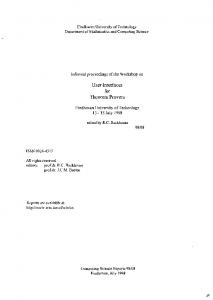
An example of a web-based form generated for JournalPaperComposite is presented in Figure 18.
4.
Related Work
In order to compare the EUIS profile with other profiles presented in the literature, this section reviews recent papers ranging in subject from modelling user interfaces of business applications to complete methodologies and tools for information system development, including its presentation aspects. Papers that deal with developing user interfaces in general are not discussed here.
ComSIS Vol. 8, No. 2, Special Issue, May 2011
419
B. Periˇsi´c et al.
Fig. 18. Managing journal papers data
The papers [21, 22], like this paper, propose the use of the problem domain model as a starting point that is transformed into a model of the user interface. The approach to modelling of application views based on the available classes (various complex panels, navigation among them) is also similar. However, [21, 22] introduces more transformation levels in order to achieve portability across different implementation platforms while not restricting to a particular fixed set of components (we deal with portability as well, but with a limited set of components). Besides, [21, 22] require the development of an information retrieval model in order to implement fetching of data used in the user interface, while we opt for implicit mapping of the user interface model to the persistence layer (the cases where implicit mapping is insufficient are defined by OCL constraints or an associated method). The authors in [21, 22] only plan the development of a tool prototype that will provide transformations of models and the application generation, while their approach is tested by manual application of transformation rules. The papers [10, 5] present a way of automatic user interface generation based on the following: a business logic model (UML activity diagrams) and a user interface model (UML class diagrams). An activity diagram is supplied with elements of the UML profile for defining system and user actions with the specified inputs and outputs, while the class diagram that is produced from the activity diagram is supplied with elements of the UML profile for user interface specification (e.g., ContainerElement, GuiElement, ActionElement). The profile does not support modelling the relationships between forms (navigation is omitted). Furthermore, obtaining classes that provide management of data from the problem domain model is not specified, although their presence is assumed
420
ComSIS Vol. 8, No. 2, Special Issue, May 2011
UML Profile for Specifying User Interfaces of Business Applications
(the dataProvider attribute in the ChoiceElement stereotype, and the methodURL attribute in the ActionElement stereotype). In [23], the authors propose the use of patterns for accelerating the user interface development. Those patterns are at a higher abstraction level and may be used in task models, presentation models, and component layout models. This paper also proposes the use of a number of tools that guide the designer in the choice and the application of patterns during modelling, assist in model synchronisation, and generate the user interface. Compared to elements of the standard presented in Section 2, the patterns used in [23] represent finer-grained application components. The paper [23] does not specify neither the relationship between the problem domain model and the user interface model, nor if there is a mapping of the generated user interface to the data persistence layer (whether the generated user interface is immediately testable in the real users’ environment). The paper [27] presents a method for developing web-based information systems based on problem domain models, applications and navigations that are directly mapped to existing development frameworks. The mapping is provided by the UML profile named FrameWeb whose stereotypes correspond with the categories of the framework used, so that the development team can deliver the implementation in a straightforward way (the implementation is manual, there are no code generators used). The majority of stereotypes in the presented UML profile are aimed at the development of the problem domain model and its mapping to the persistence layer, while support for specifying the user interface is relatively modest (there are only four stereotypes that specify the type of the web page). The series of papers [2, 8, 7, 18] presents a methodology for developing web-based information systems UWE (UML-based Web Engineering) that uses a UML profile for modelling hypermedia and the ArgoUWE tool that provides for definition of different application models, their transformation, and semiautomatic code generation. The UML profile provides for the creation of navigation models, navigation structure models, and presentation models. A navigation model is a class diagram that is extracted as a problem domain model subgraph and defines which web pages assigned to problem domain model classes are linked (associations among problem domain model classes are the link candidates). A navigation structure model is a consequence of the navigation model and defines the nature of links and additional elements needed to specify navigation (menus, indices, navigational contexts). The presentation model is a composition diagram that provides for sketching the layout of application elements although these sketches are not obligatory – the user interface layout is finalised during implementation. The concept of modelling an application in UWE methodology is the closest to the proposition in this paper – in both cases, the starting point is the problem domain model expressed as a class diagram that is automatically mapped to the application model, data model, and other models needed. Thanks to this approach, there is a direct mapping of application elements to the layer that
ComSIS Vol. 8, No. 2, Special Issue, May 2011
421
B. Periˇsi´c et al.
implements business logic, a feature missing in the majority of reviewed solutions. The most notable differences between UWE and EUIS approaches are the following: – The UWE methodology and profile are focused solely on developing webbased systems, while the methods presented here can be applied to both web and “classical” information systems. – The UWE method does not rely on an HCI standard (there is only one type of forms). – Our approach proposes a single user interface model that defines coarsegrained application building elements, their structure and layout (using the ElementsGroup stereotype), and navigation among them. Sketches of forms need not be made thanks to the mechanism for intelligent component layout that forms a usable user interface according to rules and groups, and which can be further adapted during implementation. Although not based on a UML profile, the concept of specifying GUI forms and generating the database schema and the functional prototype of the application using the IIS*Case tool [20, 11, 6] is similar to the solution presented here, apart from the order in which artifacts are implemented. Using IIS*Case, the modelling starts with specifying form types, while database schema and the prototype application are generated. Here we start with the model of the problem domain, that is used to generate the user interface model, database schema model, and the middle-tier model (in the case of three-tier architectures). After manual changes applied to these automatically obtained models, the application is generated. Our previously implemented tools for generating UIs of business applications for various platforms are presented in [12–16, 9]. All tools are based on the HCI standard presented in Section 2, but the difference is that UI model was not generated from the domain model, but was kept as metadata in the application repository. Metadata was further customised by the Form Generator tool, which utilised this information to generate source code. Metadata in the application repository, although stored in the database or an XML file and edited by a special-purpose tool, can be considered to be a DSL (domain specific language) for the description of UIs. The UI model enriched with EUIS stereotypes is based on the same metadata, but this UML-based form is more suitable for team work of experts from different fields (developers, UI design specialists, problem domain specialists, users) during application development.
5.
Conclusions
Automatic generation of UIs in the general case requires development of a number of UI models and thus needs much time and effort, often with unsatisfactory results. Synchronisation and integration among different models, is another big problem, especially in developing business applications that require tight integration of UI models with models that specify business logic.
422
ComSIS Vol. 8, No. 2, Special Issue, May 2011
UML Profile for Specifying User Interfaces of Business Applications
In order to overcome the problem of integration and to facilitate the exchange of information among different tools, UML was used to model all aspects of an application. This paper presented EUIS profile, an UML profile for specifying UIs of business applications. Being a regular UML extension, this language can be used in any general-purpose UML modelling tool and can easily be integrated with other UML-based models of the application. EUIS profile is based on our HCI standard of a business application that defines functional and presentational features of coarse-grained building blocks. Relying on this standard has enabled the rapid development of UIs for this particular type of applications at a high abstraction level, without need to develop a number of different UI models. Automatic transformation from domain to UI model additionally speed up this process. Our previous tools developed to support the presented concepts [12–16, 9] are used for the implementation of more than 70 projects of business information systems by several different development teams. The percentage of the generated code in the overall code base (database, middle tier, UI) ranged from 81.8% to 98.2%, depending on the type of application. The code generation tool that relies on the presented EUIS profile is implemented as a MagicDraw plugin. Although this tool is still in development, initial results show that the percentage of the generated code will increase when all elements are implemented. The current version does not support parsing OCL constraints. Since we have already implemented a dynamic general-purpose parser Arpeggio [1], the support for OCL expressions is soon to be finalised. Acknowledgments. Research presented in this paper was supported by Ministry of Science and Technological Development of Republic of Serbia, Grant III-44010, Title: Intelligent Systems for Software Product Development and Business Support based on Models.
References 1. Arpeggio Parser, http://code.google.com/p/arpeggio/ 2. Baumeister, H., Koch, N., Mandel, L.: Towards a UML Extension for Hypermedia Design, In: Proceedings of The Unified Modelling Language Conference: Beyond the Standard (UML 1999), France R. and Rumpe B., Eds, LNCS vol. 1723, pp. 614– 629, Springer Heidelberg (1999) 3. van den Bergh, J., Coninx, K.: Using UML 2.0 and Profiles for Modelling ContextSensitive User Interfaces, In: Model Driven Development of Advanced User Interfaces, Montego Bay, Jamaica (2005) 4. Dejanovi´c, I., Milosavljevi´c, G., Periˇsi´c, B., Tumbas, M.: A Domain-Specific Language for Defining Static Structure of Database Applications, Computer Science and Information Systems 7(3), (2010) (in print) 5. Funk, M., Hoyer, P., Link, S.: Model-driven Instrumentation of Graphical User Interfaces, In: Second International Conference on Advances in Computer-Human Interaction, Cancun, Mexico (2009)
ComSIS Vol. 8, No. 2, Special Issue, May 2011
423
B. Periˇsi´c et al. 6. Govedarica, M., Lukovi´c, I., Mogin, P.: Generating XML Based Specifications of Information Systems, Computer Science And Information Systems 1(1), pp. 117–140 (2004) 7. Knapp, A., Koch, N., Zhang, G.: Modelling the Structure of Web Applications with ArgoUWE, LNCS vol. 3140, Springer Heidelberg (2004) 8. Koch, N., Kraus, A.: The Expressive Power of UML-based Web Engineering, In: Proc. 2nd International Workshop on Web Oriented Software Technology, pp. 105– 119 (2002) 9. Komazec, S., Milosavljevi´c, B., Konjovi´c, Z.: XML Schema-Driven GUI Forms Environment, In: 11th IASTED Intl. Conf. Software Engineering and Applications, pp. 342–348, Cambridge, MA (2007) 10. Link, S., Schuster, T., Hoyer, P., Abeck, S.: Focusing Graphical User Interfaces in Model-Driven Software Development, In: First International Conference on Advances in Computer-Human Interaction, Saint Luce, Martinique (2008) 11. Lukovi´c, I., Mogin, P., Pavievi, J., Risti, S.: An Approach to Developing Complex Database Schemas Using Form Types, Software: Practice and Experience 37(15), pp. 1621-1656 (2007) 12. Milosavljevi´c, B., Vidakovi´c, M., Milosavljevi´c, G.: Automatic Code Generation for Database-Oriented Web Applications, In: Power, J., Waldron, J. (eds): Recent Advances in Java Technology: Theory, Application, Implementation. pp. 89–97, Trinity College Dublin (2003) ISBN 0954414500 13. Milosavljevi´c, B., Vidakovi´c, M., Komazec, S., Milosavljevi´c, G.: User Interface Code Generation for EJB-Based Data Models Using Intermediate Form Representations, In: Principles and Practice of Programming in Java, pp. 125–132, Kilkenny, Ireland (2003) 14. Milosavljevi´c, B., Vidakovi´c, M., Komazec, S., Milosavljevi´c, G.: User Interface Code Generation for Data-Intensive Applications with EJB-Based Data Models, In: Software Engineering Research and Practice (SERP’03), pp. 23–27, Las Vegas, NV (2003) 15. Milosavljevi´c, G., Periˇsi´c, B.: Really Rapid Prototyping of Large-Scale Business Information Systems, In: IEEE Intl. Workshop on Rapid System Prototyping, pp. 100– 106, San Diego, CA (2003) 16. Milosavljevi´c, G., Periˇsi´c, B.: A Method and a Tool for Rapid Prototyping of LargeScale Business Information Systems, Computer Science And Information Systems 2(1), pp. 57–82 (2004) 17. Milosavljevi´c, G., Ivanovi´c, D., Surla, D., Milosavljevi´c, B.: Automated Construction of the User Interface for a CERIF-Compliant Research Management System, The Electronic Library (in print) 18. Moreno, N., Melia, S., Koch, N., Vallecillo, A.: Addresing New Concerns in ModelDriven Web Engineering Approaches, In: Proc. Web Information Systems Engineering (WISE), LNCS vol. 5175, pp. 426–442, Springer Heidelberg (2008). 19. Paterno, F.: Towards a UML for Interactive Systems, In: Proc. Engineering for Human-Computer Interaction, pp. 7–18, Toronto, Canada, (2001) 20. Pavi´cevi´c, J., Lukovi´c, I., Mogin, P., Govedarica, M.: Information System Design And Prototyping Using Form Types, In: International Conference on Software and Data Technologies, pp.157–160, Setubal, Portugal (2006) 21. Schattkowsky, T., Lohmann, M.: Towards Employing UML Model Mappings for Platform Independent User Interface Design, In: Model Driven Development of Advanced User Interfaces, Montego Bay, Jamaica (2005)
424
ComSIS Vol. 8, No. 2, Special Issue, May 2011
UML Profile for Specifying User Interfaces of Business Applications 22. Schattkowsky, T., Lohmann, M., UML Model Mappings for Platform Independent User Interface Design, In: MoDELS 2005 Workshops, LNCS 3844, pp. 201-209, Springer, Heidelberg (2006) 23. Seffah, A., Gaffar, A.: Model-Based User Interface Engineering with Design Patterns, Journal of Systems and Software 80(8), pp. 1408–1422 (2007) 24. Shneiderman, B.: Designing the User Interface: Strategies for Effective HumanComputer Interaction, Addison-Wesley, Third Edition (1998) 25. da Silva, P.P.: User Interface Declarative Models and Development Environments: A Survey, In: Proc. Design, Specification and Verification of Interactive Systems, LNCS vol. 1946, pp. 207–226, Limerick, Ireland (2000) 26. da Silva, P.P., Paton, N.W.: Improving UML Support for User Interface Design: A Metric Assessment of UMLi, In: Workshop on Bridging the Gaps Between Software Engineering and Human-Computer Interaction at International Conference on Software Engineering (ICSE 03), pp. 76–83, Portland, Oregon, USA (2003) ˆ ao ˜ Silva Souza, V., Almeida Falbo, R., Guizzardi, G.: A UML Profile for Mod27. Estev elling Framework-based Web Information Systems, In: Workshop on Exploring Modelling Methods for Systems Analysis and Design (EMMSAD’07), pp. 149–158, (2007)
ˇ c´ is an associated professor at University of Novi Sad, Faculty Branko Perisi of Technical Sciences. He has received his engineer diploma from University of Sarajevo, Faculty for electrical engineering, M.Sc. and PhD diplomas from University of Novi Sad, Faculty of Technical Sciences. He is currently a Computer center manager and head of Software development team at Faculty of Technical Sciences. As a teaching professor he has developed and teached a variety of Computer Engineering, Software Engineering and Information System Design courses at different Universities. His major research interests are related to Model Driven Software Development, Business Information Systems Design, Software Configuration Management and Secure Software Design. Gordana Milosavljevic´ is an assistant professor at University of Novi Sad, Faculty of Technical Sciences. She teaches courses in Business Information Systems and Model Driven Software Development. Her research interests focus on software engineering methodologies, rapid development tools and enterprise information systems design. Igor Dejanovic´ received his M.Sc. (5 years, former Diploma) degree from the Faculty of Technical Sciences in Novi Sad. He completed his Mr (2 year) degree at the University of Novi Sad, Faculty of Technical Sciences. Currently, he works as a teaching assistant at the Faculty of Technical Sciences at the University of Novi Sad, where he assists in teaching several Computer Science and Software Engineering courses. His research interests are related to Domain-Specific Languages, Model-Driven Engineering and Software Configuration Management.
ComSIS Vol. 8, No. 2, Special Issue, May 2011
425
B. Periˇsi´c et al.
Branko Milosavljevic´ is an associate professor at University of Novi Sad, Faculty of Technical Sciences. He teaches courses in Net-Centric Computing, XML and Web Services, and Security in E-Business Systems. His research interests include information retrieval, digital libraries, document management and information security.
Received: January 12, 2011; Accepted: May 5, 2011.
426
ComSIS Vol. 8, No. 2, Special Issue, May 2011