employing both packet marking and data logging in a distributed manner ... proposed a deterministic packet marking scheme in [7], while Savage et.al. pro-.
Unified Defense against DDoS Attacks M. Muthuprasanna, G. Manimaran, Z. Wang Iowa State University, Ames, IA, USA - 50011 {muthu, gmani, zhengdao}@iastate.edu Abstract. With DoS/DDoS attacks emerging as one of the primary security threats in today’s Internet, the search is on for an efficient DDoS defense mechanism that would provide attack prevention, mitigation and traceback features, in as few packets as possible and with no collateral damage. Although several techniques have been proposed to tackle this growing menace, there exists no effective solution to date, due to the growing sophistication of the attacks and also the increasingly complex Internet architecture. In this paper, we propose an unified framework that integrates traceback and mitigation capabilities for an effective attack defense. Some significant aspects of our approach include: (1) a novel data cube model to represent the traceback information, and its slicing along the lines of path signatures rather than router signatures, (2) characterizing traceback as a transmission scheduling problem on the data cube representation, and achieving scheduling optimality using a novel metric called utility, (3) and finally an information delivery architecture employing both packet marking and data logging in a distributed manner to achieve faster response times. The proposed scheme can thus provide both per-packet mitigation and multi-packet traceback capabilities due to effective data slicing of the cube, and can attain higher detection speeds due to novel utility rate analysis. We also contrast this unified scheme with other well-known schemes in literature to understand the performance tradeoffs, while providing an experimental evaluation of the proposed scheme on real data sets.
1
Introduction
Denial-of-Service (DoS) attacks are a menace we have come to live with in today’s Internet. Distributed DoS attacks on several sites including Yahoo and eBay, and against root DNS servers had virtually paralyzed the Internet in early 2000s. Recent attacks motivated by political and economic reasons on SCO, RIAA, 2Checkout, Blue Security, EveryDNS etc. have established a disturbing trend, and unless we address this issue now, there might soon be an avalanche of DDoS attacks crippling the entire Internet infrastructure. The stateless nature and destination-oriented routing of the Internet makes tracking of attackers, employing source address spoofing, a difficult problem to address [1] [2]. The need of the hour is a technique that not only traces attackers but also aids in effective mitigation of the ongoing attacks [3]. To be realistically applicable on an Internet scale, the proposed schemes must be incrementally deployable, scalable, require minimal changes to existing
hardware, maintain high accuracy during large volume attacks, resist tampering by spoofed data injection, and require very few packets to complete traceback while also simultaneously triggering mitigation, amongst other requirements. The traceback schemes in literature address the problem of collecting information about individual packet forwarding agents and collating this data to obtain attack source/path statistics; while the mitigation schemes address the problem of dropping malicious packets using the concept of path identifiers and do not overtly concern themselves with the identification of the attackers themselves. We analyze the traceback problem here as independent data representation and data transmission issues. We also propose a novel data model and metric to help us better evaluate traceback schemes. We also exploit the concept of path signatures here so that the proposed traceback scheme can additionally support effective mitigation, thus realistically obtaining the better of the two worlds. The rest of the paper is organized as follows. Section 2 reviews the different schemes known, while Section 3 presents the basic principle and motivation behind the proposed solution. Sections 4 and 5 discuss the data representation and the data transmission phases respectively. Section 6 analyzes the performance tradeoffs, while Section 7 concludes.
2
Related Work
The earliest work on DDoS defense led to the concept of network traceback [4] by Burch and Cheswick. Bellovin et.al. proposed ICMP-based out-of-band messaging in iTrace [5], while Snoeren et.al. proposed SPIE [2] employing packet logging, which was subsequently improved by Li et.al. in [6]. Belenky and Ansari proposed a deterministic packet marking scheme in [7], while Savage et.al. proposed a probabilistic packet marking (PPM) technique in [1], with subsequent enhancements made by others in [8] [9] [10] [11]. IP address fragmentation for efficient packet marking and their vulnerability to attacker induced noise have been studied in [12] and [13] respectively. Recently, various encoding techniques have been used to progressively improve the performance of PPM schemes, as in Tabu marking [14], Local Topology marking [15], Space-Time encoding [16], Color Coding [17], and the use of Huffman Codes [18], Algebraic Geometric Codes [19] etc. Additionally various architectures for traceback have been explored, such as inter-domain traceback [20] and hybrid traceback [21] [22], in addition to some other radical approaches like in [23]. Research on mitigating DDoS attacks has proceeded in parallel, focusing on network ingress filtering [24], routing table enhancements as in SAVE [25], CenterTrack [26] and intelligent filtering [3]. The concept of path fingerprints was exploited by Yaar et.al. in [27], and subsequently improved in [28]. Various other techniques involving path filtering [29] [30], statistical filtering [31] [32], and rate limiting [33] [34] have also been explored in literature. Of late, the focus has been on unifying these strategies for greater deployment incentives and better defense capabilities for the Internet.
3
Motivation
We discuss a few reasons here that motivate and also form the basis of our proposed solution. Our aim here is to provide a single mechanism that supports both traceback and mitigation simultaneously with no additional overhead. Unified Operation: Traditional PPM traceback schemes capture per-hop behavior, i.e. they transmit information about each intermediate router to the victim so that a global view of the routing path is eventually obtained over multiple packets. Thus traceback data is incrementally gathered and does not function on a per-packet basis; where each packet corresponds to some router identifier fragment, and state maintenance is needed for mitigation. Similarly, traditional mitigation schemes capture end-to-end behavior, i.e. at some level of abstraction they generate fingerprints that identify the routing paths as opposed to routers themselves. Thus mitigation operates on a per-packet granularity, but lossy abstraction makes it impossible to perform accurate traceback [27]. Our approach entails slicing the entire traceback data (later modeled as a cube) along the lines of path signatures instead of individual router identifiers. Thus we obtain multiple signatures per routing path useful for mitigation at lower thresholds on a per-packet basis, and when viewed collectively yields the required traceback data too. Thus we build a homogeneous technique that seamlessly provides both traceback and mitigation capabilities, operating in parallel. Traditional Restrictions: As the number of bits in the IP headers that can be overloaded to support traceback in the Internet is limited [1], we not only need to reduce the total number of bits to be marked, but also the number of bits marked per packet. Additionally to support faster traceback, we also need to mark these bits across fewer packets. Thus an ideal scheme would need to optimize these three different metrics simultaneously. Practical Deployment: We assume that the victim has an upstream router graph [11] that serves as a lookup table for suspect routing paths. Hence, the scope of the problem is limited to identifying a unique path (essentially unique set of connected routers) in the router graph and not the entire Internet. As this is not an exhaustive set, we need to obtain only a certain subset of all router identifier fragments, that ensures uniqueness in the router graph. Note that there exist multiple such subsets of different sizes in the router graph. Use of router identifier fragments as base data unit might lead to transmitting more fragments than required to uniquely identify a certain router, thereby wasting entire packets at times. In contrast, use of path signatures as base data unit ensures that every router has some data to convey to the victim in every packet. Thus we ensure maximum data diversity for the victim by increasing the average information (utility) gained per bit transmitted, and achieve traceback in far fewer (bits) packets due to better (bit) packet space utilization. We address these issues in two main phases - the data representation phase where we address the different theoretical and technical issues by defining a novel data cube model for traceback and a new metric called utility to analyze
the model, and the data transmission phase where we address the practical implementation issues by employing limited data logging at intermediate routers.
4
Data Representation Phase
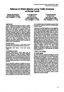
We present our data cube model and other fundamental concepts here that form the crux of our solution. The question we answer here is which bits do we prefer to send, as opposed to how we send them as addressed by Adler in [9]. Data Cube: The total information (in bits) needed by the victim to completely reconstruct a suspect routing path is called the Traceback Data and we represent it using the Data Cube in Fig.1(a). The y-axis in the cube represents the different routers along the routing path, while the x-axis represents the different fragments of the corresponding router identifiers. The z-axis in the cube represents the different bits in a particular fragment of the router identifier. Thus the cube represents the complete traceback data about the suspect Internet routing path. The shaded region in Fig.1(a) shows the router identifier for a particular router, including the different bits in all the different fragments. This 3-D representation helps us analyze the optimality of the different traceback schemes known.
(a)
(c)
(b)
(d)
Fig. 1. Traceback Data Cube Model & Different Transmission Schedules
When a DoS attack is launched, the search space for the suspect routing path is the entire Internet (or rather the entire upstream router graph). The victim
then prunes this domain to a unique path, based on the traceback data it receives in an incremental fashion. It is obvious that the speed of the traceback operation is thus determined by the rate of receiving useful incremental information. Thus the transmission schedule used to transmit the entire traceback data to the victim plays a critical role in determining its response time to attacks. We define a metric called Utility, which helps us choose an optimal transmission schedule for the traceback data cube. The basic idea is to associate each of the bits in the data cube with different weights (or utilities), such that an objective of maximizing speed (or total utility) yields a natural optimal transmission (sequence) schedule. Utility: We define Information Utility of a particular bit [35] as the ratio of the reduction in the search space due to the receipt of that particular bit to the total original search space (Eqn.1). The search space for a particular router having a k-bit identifier is evidently 2k . Receipt of a single bit reduces the search space (uncertainty) to 2k−1 . A second subsequent bit reduces it to 2k−2 and so on. U tility (ui ) =
Search Space Reduction i T otal Search Space
(1)
Thus the utilities of the first, second and mth -bits of a k-bit message are as shown in Eqns.2,3. The terms first, second and so on here do not refer to the digits in the MSB or LSB of the binary number, rather they refer to that bit (any one of the k bits) that was transmitted first, second and so on. u1 =
1 2k − 2k−1 = ; k 2 2 um =
u2 =
1 2k−1 − 2k−2 = 2 k 2 2
2k−(m−1) − 2k−m 1 = m k 2 2
(2)
(3)
The total utility of all bits of a message is shown in Eqn.4. The 21k represents the self-information of a k-bit message. In other words, it represents the probability of finding that particular k-bit message in the entire search space, and is the implicit information it possesses. Thus the total utility of the data cube having r intermediate routers is ≈ r, where each router identifier has utility ≈ 1. k X i=1
ui =
k X 1 1 =1− k i 2 2 i=1
(4)
We thus see that not every bit of information in the traceback data cube has the same utility, as has been assumed by researchers to date. The utility of a bit is governed by how much information has already been transmitted to the victim about a particular slice (router identifier) in the cube. Higher the utility achieved in a certain fixed number of packets, smaller the search space for the suspect routing path, and hence faster the traceback process. We now use these novel concepts of data cube and utility, to derive higher utility rate transmission schedules for the data cube and hence faster traceback schemes.
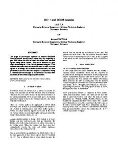
Utility Analysis: We analyze the basic PPM based traceback scheme [1] here, as it has been the most widely studied technique in literature, and also as its analysis holds true for all the different flavors of PPM schemes proposed to date. We quantify the utility rate of the basic PPM scheme clearly demarcating its operating region in the utility space, thus illustrating its sub-optimal performance.
Fig. 2. Utility Rate Comparison
The 3-D data cube when viewed as a 2-D surface (xy-plane), each unit cell corresponds to a vector (z-axis) as indicated in Figs.1(b),1(c). The PPM scheme now reduces to randomly choosing a unit cell (with replacement) from the 2-D surface and sending the corresponding bit-vector to the victim. The receipt of all bit-vectors according to some transmission schedule concludes the traceback process. If the r router identifiers are each split into k fragments, each m bits long, then the utilities of the first, second and tth fragments for each router identifier are as shown in Eqns.5,6. uF1 = (1 −
uFt =
1 1 1 ) ; uF2 = ( m ) ∗ (1 − m ) 2m 2 2
mt X i=m(t−1)+1
ui = (
1 2m(t−1)
) ∗ (1 −
1 ) 2m
(5)
(6)
Hence, highest (lowest) utility rate is achieved when all high (low) utility fragments are scheduled first for transmission. Consider the transmission schedule in Fig.1(b) where all routers send their first fragment, then their second fragment, and so on. Also consider another transmission schedule in Fig.1(c) where a particular router sends all its fragments before the next router is allowed to transmit, as in an implicit token passing system. These represent the highest and lowest utility rate transmission schedules respectively. It is easily seen that any other transmission schedule attains a utility rate in the operating region bounded by the inner two curves in Fig.2.
Proposed Transmission Schedule: Now consider a different transmission schedule, where we again view the data cube as a 2-D surface (xz-plane), where each unit cell corresponds to a vector (y-axis) as indicated in Fig.1(d). We thus logically move away from the concept of individual router identifiers to that of path signatures. All the routers now send their first bit, then their second bit and so on in each packet. Any packet now has only one bit from each router in order, and is hence classified as a path fingerprint (signature). The utilities for the first, second, and tth packets are as shown in Eqn.7. uP1 =
1 m m m ; uP2 = 2 ; uPt = m ∗ t = t 2 2 2 2
(7)
The operating region in utility space of the proposed transmission schedule is bounded by the outer two curves in Fig.2. The lower bound here is caused by the Leader Selection Problem discussed later. In Fig.2, we assume r=16 (routers), k=4 (fragments), m=16 (bits), for illustrative purposes only.
5
Data Transmission Phase
Implementing the proposed scheme requires distributed coordination by all the intermediate routers to resolve mainly 2 issues. Firstly, each router needs to know the exact bit position in the IP headers that it is supposed to mark based on its distance from the victim. Also, the first router closest to the attacker, needs to decide which one of the multiple path signatures is to be marked on a certain packet by all the subsequent routers along the suspect routing path.
Fig. 3. Traceback Buffer Implementation
We adopt a queue implementation to resolve the first problem [28]. Any new router mark is pushed at the buffer head, causing some bit at the tail to overflow (Fig.3). Thus we ensure that without any explicit messaging, we can retain the marks of the last k routers in the traceback field in the IP packet header. To prevent the queue from being hijacked by attacker injected spoofed data in the absence of overflow, we would need the first router along the routing path to reset the traceback buffer. Additionally, it would also need to probabilistically choose a particular path signature to be marked on a certain packet. As there is no consensus on how we determine the first router in the research community, we dilute the definition of a first router to represent the router farthest from the victim in a trust domain (ISP PoP, gateway router etc.) [12]. Although this limits the depth of traceback that can be achieved, the mitigation accuracy is enhanced due to virtually no data tampering by the attackers.
Leader Selection Problem: As an alternative to the trust domain, we could also sub-optimally allow each router to probabilistically choose to be the leader (or first router). This probabilistic selection was first explored in [1]. The probabilistic worst case where the router closest to the victim always chooses to be the leader results in the lower bound for the proposed scheme in Fig.2.
Fig. 4. Hybrid Traceback Architecture
Hybrid Architecture: To improve the average case performance of Probabilistic Leader Selection (PLS), we now propose the hybrid traceback architecture (Fig.4), employing both packet logging and marking techniques [21]. Here, we additionally require the leader to cache the current traceback buffer and the path signature index, before overwriting them. Every other (non-leader) router during marking compares the current traceback buffer and index with its cache (if present), and on a prefix match caches and then marks the longer prefix. The example in Fig.4 shows a packet where both routers 1 and 4 contend to be the leader, and consequently marks from routers 1,2,3 are lost (but cached at router 4). In a subsequent packet, where router 2 is the leader, router 4 can augment the traceback buffer with cached mark of router 1 also. To keep the storage overhead small, routers can optionally also choose to turn this caching off. Thus selective pipelined distributed network storage of traceback data yields a significant improvement in achieving higher transmission utility rates, and hence faster traceback using far fewer packets.
6
Analysis & Experimental Evaluation
We compare the basic PPM based traceback scheme and the proposed utility based scheme here, while also evaluating the effect of the hybrid architecture. Number of Packets (w.r.t. PPM): Let there be r routers along the routing path, each having a marking probability of p, and whose identifiers each have k m-bit fragments. The probability of receiving a mark from a router i hops away is Pi (Mm ) (Eqn.8(a)). If we conservatively assume that marks from all routers appear with same likelihood as the furthest router, then probability that a packet delivers a mark from some router is P (Mm ) (Eqn.8(b)). From generalized Coupon Collector Problem [36] [37] in Probability Theory, and detailed analyses in [1] [17], number of packets Xm needed to reconstruct the routing path from all the different fragments for PPM based scheme is given by Eqn.9. Pi (Mm ) = p(1 − p)i−1 ; P (Mm ) ≥ rp(1 − p)r−1
(8)
E[Xm ]