This article has been accepted for publication in a future issue of this journal, but has not been fully edited. Content may change prior to final publication. 1
Unitary Linear Dispersion Code Design and Optimisation for MIMO Communication Systems Ming Jiang*, Member, IEEE, and Lajos Hanzo, Fellow, IEEE
Abstract Linear Dispersion Codes (LDCs) have recently attracted numerous research interests. Thanks to their efficient spreading of data across both the time and spatial domains, LDCs are capable of achieving a desired DiversityMultiplexing Trade-off (DMT) in Multiple Input Multiple Output (MIMO) broadband wireless access systems. This paper proposes a novel LDC design method, which relies on the unitary matrix theory combined with a Genetic Algorithm (GA) aided optimisation procedure. The proposed design provides a flexible framework, where new LDCs attaining higher data rates and better error resilience than a number of classic MIMO schemes can be generated. Index Terms Diversity-multiplexing trade-off, genetic algorithm, multiple-input multiple-output, linear dispersion code.
I. I NTRODUCTION
T
HE Diversity-Multiplexing Trade-off (DMT) represents a compromise between the achievable data rate (link throughput) and diversity gain (error resilience) in Broadband Wireless Access (BWA) systems. Among other
techniques, the family of Linear Dispersion Codes (LDCs) [1], [2] was found to be capable of achieving a flexible DMT, thanks to their capability of exploiting both spatial and time (or frequency) diversity. The concept of LDCs [1] introduces a generalised Multiple-Input Multiple-Output (MIMO) framework, which subsumes the Vertical Bell Labs Layered Space-Time (V-BLAST) [3] and Spatial Multiplexing (SM) type techniques, as well as a wide range of Space-Time Codes (STC), such as Alamouti’s [4] and Tarokh’s codes [5]. At the receiver side, the different LDCs can be decoded by the same set of decoders as those designed for the conventional STCs. These include the Minimum Mean Square Error Decoder (MMSED), the Maximum Likelihood Decoder (MLD), the Sphere Decoder (SD) and other BLAST-type decoders. Conventional LDC design methods include the classic constructions [4], [5], gradient-based search algorithms [1], [6], [7], the frame theory [2] and the algebraic theory [8]–[10]. Design criteria such as maximising the ergodic c 2010 IEEE. Ming Jiang was with Samsung Electronics Research Institute, Staines, UK and is now with New Postcom Copyright ° Equipment Co., Ltd., Guangzhou, China (email:
[email protected]). Lajos Hanzo is with School of Electronics and Computer Science, University of Southampton, UK (email:
[email protected]). Copyright (c) 2009 IEEE. Personal use is permitted. For any other purposes, Permission must be obtained from the IEEE by emailing
[email protected]. Authorized licensed use limited to: UNIVERSITY OF SOUTHAMPTON. Downloaded on February 1, 2010 at 18:15 from IEEE Xplore. Restrictions apply.
This article has been accepted for publication in a future issue of this journal, but has not been fully edited. Content may change prior to final publication. 2
channel capacity or Mutual Information (MI) [1], minimising the Pair-wise Error Probability (PEP) [5] and the Block Error Probability (BLEP) [7], etc. are often used for optimising LDCs [11]. Since analytical expressions of the above-mentioned criteria are not always available, numerical methods, many of which employ gradient-based search algorithms [1], [6], [7] have been found to be more flexible and effective for a wide range of scenarios. However, most of these methods may converge to a local minimum only [7]. In contrast to the above design options, the novelty of this paper is that we devise a new design approach using Genetic Algorithms (GA), where a specific unitary matrix transform module is employed. Unitary LDCs have been shown to be asymptotically optimal [6]. To the best of our knowledge, the proposed novel LDC design framework appears to be the first GA-aided technique, which is capable of exploring the entire space of unitary matrices according to the unique Haar measure, where optimised unitary LDCs exhibiting a better performance than many of their existing counterparts can be found. GAs constitute powerful global optimisation methods that are efficient in solving complex non-linear optimisation problems [12]. We have demonstrated that with the aid of appropriate operators, GAs are capable of conducting a ‘guided’, rather than a purely random search [13], thus distinguishing them from many random optimisation methods. Constrained by the LDC optimisation problem, the proposed GA exploiting a non-binary matrix encoding method increases the search granularity, thus providing a higher degree of freedom in our design. We also design a new hybrid non-binary mutation operator constituted by the joint modulo and polarity-flipping controller. Thanks to the flexibility of the new design framework, it is also possible to produce LDCs with various dimensions for both square and non-square encoding matrices. The organisation of this paper is as follows. A brief review of LDCs is provided in Section II-A, followed by our elaboration on the unitary matrix transform module in Section II-B. The proposed GA-aided optimisation procedure is described in Section II-C. Finally, we present our simulation results and conclusions in Sections III and IV, respectively. II. P ROPOSED LDC D ESIGN F RAMEWORK A. Linear Dispersion Codes An LDC is fully specified, given a set of so-called dispersion matrices or encoding matrices, which can have real or complex valued entries [1]. Let M and N denote the number of transmit and receive antennas, respectively. The (T × M ) LDC codeword matrix S, where T is the number of time slots in each codeword, is defined by: S=
Q X
(αq Aq + jβq Bq ),
(1)
q=1
Copyright (c) 2009 IEEE. Personal use is permitted. For any other purposes, Permission must be obtained from the IEEE by emailing
[email protected]. Authorized licensed use limited to: UNIVERSITY OF SOUTHAMPTON. Downloaded on February 1, 2010 at 18:15 from IEEE Xplore. Restrictions apply.
This article has been accepted for publication in a future issue of this journal, but has not been fully edited. Content may change prior to final publication. 3
where Aq and Bq are the set of dispersion matrices. The set of {αq , βq } is defined by sq = αq + jβq , where sq is a complex symbol from a given m-PSK or m-QAM constellation. In the quasi-static (M × N ) MIMO system model, we have:
r X=
ρ SH + V, M
(2)
where X is the (T × N ) received signal matrix, H is the (M × N ) channel matrix which is assumed to be timeinvariant during the duration T , V is the (T × N ) Additive White Gaussian Noise (AWGN) matrix whose entries are zero-mean, unit-variance, complex-Gaussian variables, and ρ is the Signal-to-Noise Ratio (SNR) at each of the N receive antennas, which is independent of M . The effective data rate is defined as R = Rc · log2 (m), where Rc =
Q T
is the LDC’s code rate.
B. Matrix Unitarisation Our objective is to devise a specific design framework that produces the set of unitary dispersion matrices Aq and Bq based on a given criterion. In order to find good unitary LDCs, it is beneficial to explore the entire unbiased unitary space under specific LDC design constraints. The LDC matrix unitarisation method employed in our design framework of Fig. 1 is based on the random unitary matrix theory [14]–[16]. Note that the unitary matrices’ elements are not independent random variables, making the numerical generation of such random matrices complicated [16]. However, Hurwitz [15] proposed a convenient method to parameterise the space of unitary matrices by K 2 independent parameters, where K is the dimension of the matrices concerned. Provided random Euler angles as input, the method forms elementary unitary transformations in two-dimensional subspaces to create an arbitrary unitary transformation. Combined with the GA-based search method of Section II-C, optimised unitary LDCs may be found spanning the entire unbiased space of unitary matrices, rather than spanning only a fraction of it. The proposed procedure is highlighted below. Let K = max(T, M ). We carry out the following steps to construct a unitary LDC: Step 1: Initialise the MIMO and LDC parameters, namely M , N , T , Q, ρ, etc. Generate an external control matrix Λ: (3)
Λ = [Λ1 , Λ2 , · · · , Λ2Q ] , (r,s)
where the q -th column vector Λq is defined as Λq = [ψq
(s)
(r,s)
, χq , ξ q
(r,s)
, αq ]T , and ψq
(s)
(r,s)
, χq , αq , ξq
(q =
1, · · · , 2Q, 0 ≤ r < s ≤ K − 1) are real numbers within the predefined ranges: ψq(r,s) ∈ [0, 2π), χq(s) ∈ [0, 2π), ξq(r,s) ∈ [0, 1), αq ∈ [0, 2π). (r,s)
It is worth pointing out that for all legitimate combinations of ψq
(s)
(r,s)
, χq , ξ q
(4)
, αq in (4), the ensemble of the
Copyright (c) 2009 IEEE. Personal use is permitted. For any other purposes, Permission must be obtained from the IEEE by emailing
[email protected]. Authorized licensed use limited to: UNIVERSITY OF SOUTHAMPTON. Downloaded on February 1, 2010 at 18:15 from IEEE Xplore. Restrictions apply.
This article has been accepted for publication in a future issue of this journal, but has not been fully edited. Content may change prior to final publication. 4
Start Initialisation (MIMO and LDC Parameters) Generate External Control Matrix Λ ξq Generate Control Vector φ ψ q , χ q ,α q φq Combine Internal Control Matrix Λ′ Extract Columns of Λ′
Λ′1
Λ′2Q
Λ ′2
ψ 2 Q , χ 2Q , φ 2Q ψ 1 , χ1 , φ1 ψ 2 , χ 2 ,φ 2 Matrix Matrix Matrix … Rotations Rotations Rotations E 2Q, k α1 α2 α 2Q E1,k E 2, k Calculate Calculate Calculate Unitary Matrix Unitary Matrix Unitary Matrix ~ ~ U1
~ U2
U2Q
Apply Transmit Power Constraint TM Comparison of T and M T=M Column Matching
Derive Dispersion Matrices … B1 A2 B2
AQ
BQ
End Fig. 1.
The flowchart of the LDC matrix unitarisation process.
resultant unitary dispersion matrices will constitute the full unitary matrix space according to the unique Haar measure [16]. We will discuss how to initialise Λ in Section II-C. (r,s)
Step 2: Calculate a control vector Φ = [φ1
(r,s)
, φ2
(r,s)
(r,s)
, · · · , φ2Q ], φq
(r,s) 1/(2r+2) ) ],
= arcsin[(ξq
(r,s)
where ξq
is defined by (4). Then, from Λ and Φ, create an internal control matrix Λ0 = [Λ0 1 , Λ0 2 , · · · , Λ0 2Q ], where (r,s)
Λ0 q = [ψq
(s)
(r,s)
, χq , φq
, αq ]T , q = 1, · · · , 2Q, 0 ≤ r < s ≤ K − 1.
Step 3: Conduct unitary transformation according to the random unitary matrix theory [14], [16]. First, for each
Copyright (c) 2009 IEEE. Personal use is permitted. For any other purposes, Permission must be obtained from the IEEE by emailing
[email protected]. Authorized licensed use limited to: UNIVERSITY OF SOUTHAMPTON. Downloaded on February 1, 2010 at 18:15 from IEEE Xplore. Restrictions apply.
This article has been accepted for publication in a future issue of this journal, but has not been fully edited. Content may change prior to final publication. 5
column vector Λ0 q , construct (K − 1) number of rotated unitary matrices Eq,k , k = 1, · · · , K − 1: (K−1,K)
Eq,1 = Eq
(0,1)
(φq
(K−2,K−1)
Eq,2 = Eq
(K−1,K)
Eq .. .
(0,2)
(φq
(1,2)
(φq
(0,2)
, ψq
(1)
, χq )
(1,2)
, ψq
, 0)·
(2)
, χq )
(5) (1,2)
Eq,K−1 = Eq (2,3)
Eq
(0,1)
, ψq
(K−2,K−1)
(φq
(K−3,K−1)
(φq
(K−1,K)
· · · Eq
(K−2,K−1)
, ψq
(K−3,K−1)
, ψq
(0,K−1)
(φq
, 0)·
(0,K−1)
, ψq
(r,s)
(r,s)
, 0)·
(K−1)
, χq
(r,s)
)
(s)
where the set of so-called elementary unitary matrices Eq (φq , ψq , χq ) are given by [16]: (r,s) (r,s) (r,s) E E · · · E q,12 q,1K q,11 (r,s) (r,s) (r,s) E E · · · E q,21 q,22 q,2K E(r,s) = , q . . . . .. .. .. .. (r,s) (r,s) (r,s) Eq,K1 Eq,K2 · · · Eq,KK (r,s)
(r,s)
(r,s)
where the non-zero elements are defined by: Eq,kk = 1 (k = 1, · · · , K; k 6= r, s), Eq,rr = cos φq (r,s)
sin φq
(s)
(r,s)
(r,s)
· exp(jχq ), Eq,sr = − sin φq
(s)
(r,s)
(r,s)
· exp(−jχq ), Eq,ss = cos φq
(r,s)
· exp(−jψq
(6)
(r,s)
·exp(jψq
(r,s)
), Eq,rs =
). Then, the 2Q unitary
˜ q can be calculated as [16]: matrices U ˜ q = exp (jαq ) · Eq,1 · Eq,2 · · · Eq,K−1 , q = 1, · · · , 2Q. U q
Apply the transmit power constraint such that Uq =
K Q
(7)
˜ q. ·U
Step 4: Derive the LDC dispersion matrices based on the associated dimension requirement. If T = M , we have: Aq = Uq , q = 1, · · · , Q . (8) B = U , q = Q + 1, · · · , 2Q q
q
If T < M , the dispersion matrices are created by selecting T out of the K rows in the matrix Uq to form a new (T × M ) matrix. The process for the case of T > M is similar. C. Genetic Algorithm aided LDC Optimisation The algorithm described in Section II-B provides a convenient way of generating the ensemble of unitary matrices, but it does not impose any constraint on the characteristics of these unitary LDC matrices. Therefore, the GA-aided LDC optimisation framework of Fig. 2 is proposed for optimising the candidate unitary LDCs. The genetic operators were carefully selected to ensure that their combination constitutes an efficient heuristic mechanism. Due to space Copyright (c) 2009 IEEE. Personal use is permitted. For any other purposes, Permission must be obtained from the IEEE by emailing
[email protected]. Authorized licensed use limited to: UNIVERSITY OF SOUTHAMPTON. Downloaded on February 1, 2010 at 18:15 from IEEE Xplore. Restrictions apply.
This article has been accepted for publication in a future issue of this journal, but has not been fully edited. Content may change prior to final publication. 6
limitations, in the sequel we only describe the proposed framework without elaborating on the GA’s operations.
Input Parameters
Start
Interested readers are referred to [12] for more detailed information on GAs. Random
MIMO Parameters
Deterministic Predefined
LDC Parameters
From Previous Searches
Controller Initial Matrix Λ
Channel Parameters
Hybrid Non-Binary Mutation g=1 Create Population Ξ Capacity
Modulo & PolarityFlipping Control
Matrix Unitarisation
Determinant Rank & Determinant Rank & Trace
Controller
Criteria Selection
Initialisation
Cost Function Evaluation Elitism Control (only for g>1)
… Best Candidate Λbest
g = G?
No g = g+1 Create Mating Pool
Buffer Dimension Matching A q , B q , q = 1,
Yes
L, Q
Calculate Selection Probability Selection and Pairing
End Blend Crossover Modulo & PolarityFlipping Control Fig. 2.
Hybrid Non-Binary Mutation
The flowchart of the process for generating unitary LDCs.
First, the control matrix Λ defined in (3) has to be initialised. Subject to (4), its elements’ values can be generated randomly, or according to deterministic rules, for example, by deriving the corresponding Λ from a known unitary LDC (such as the Alamouti code [1]), or by using the values optimised in a previous search. According to our experience, a combination of the above three options can help to provide good results, while at the same time mitigating premature convergence to local minima. Based on Λ, we create a so-called Population set, Ξ = {Λ[i]} (i = 1, · · · , P ), with the aid of a hybrid non-binary mutation operator, which jointly perturbs its Copyright (c) 2009 IEEE. Personal use is permitted. For any other purposes, Permission must be obtained from the IEEE by emailing
[email protected]. Authorized licensed use limited to: UNIVERSITY OF SOUTHAMPTON. Downloaded on February 1, 2010 at 18:15 from IEEE Xplore. Restrictions apply.
This article has been accepted for publication in a future issue of this journal, but has not been fully edited. Content may change prior to final publication. 7
elements by constrained random quantities to prevent early convergence to a local optimum, and hence facilitates finding the global optimum. More specifically, a modulo-(2π ) operator is applied to ψq , χq , αq and a polarity-flipping operator is applied to ξq , respectively, ensuring that their mutated values fall within the ranges specified in (4): ψq,new = (ψq,old + λ · ∆) mod (2π) χq,new = (χq,old + λ · ∆) mod (2π) , αq,new = (αq,old + λ · ∆) mod (2π) −ξ, if ξ < 0 ξq,new = , ξ = ξq,old +λ · ∆ 2 − ξ, if ξ > 1
(9)
where we have ∆ = 1/(2π) and λ ∈ {1, −1}. The entire Population Ξ is referred to as a Generation. Each element in Ξ has the same dimension as Λ and is called an Individual. The matrix unitarisation process of Section II-B is invoked for each GA Individual, in order to transform it to 2Q number of unitary dispersion matrices Aq and Bq (q = 1, · · · , Q). These dispersion matrices, which together fully specify an LDC, will be evaluated according to a cost function, namely the determinant criterion of [6]. However, diverse criteria can be applied or combined, as indicated by the “Criteria Selection” module shown in Fig. 2. The evaluation process will assign a score to each Individual, which quantifies its fitness with respect to the specific criteria employed. The Individuals having high fitness values will be selected to form a Mating Pool, where each of them is assigned a specific selection probability [12]. According to their selection probabilities, two Individuals are then selected for forming a pair of Parents. The total number of Parent pairs is P/2, where P is the Population size. Each pair is subject to a blend crossover and the aforementioned hybrid mutation operations, resulting in two Offspring, namely in two new Individuals. All Offspring jointly will form a new Generation and their fitness will be evaluated accordingly. In order to retain the high-fitness Individuals from one Generation to the next, an Elitism control function is applied to replace the worst Individuals of the new Generation with the best ones of the previous Generation [12]. The above-mentioned optimisation process iterates, until the Generation index reaches a maximum predefined value of G. In the last generation, the Individual that yields the highest score will be considered as the solution, namely the optimised LDC. In addition, the “Dimension Matching” function seen in Fig. 2 and detailed in Section IIB is invoked to provide non-square LDCs, if required. The complexity of the optimisation procedure depends on a number of design aspects, such as for example the dimensions of the LDCs and the Population size P as well as the number of Generations G used. When these are large, the complexity can be high. However, we point out that the proposed framework is employed offline, making the search for high-dimension LDCs possible for open-loop transmissions.
Copyright (c) 2009 IEEE. Personal use is permitted. For any other purposes, Permission must be obtained from the IEEE by emailing
[email protected]. Authorized licensed use limited to: UNIVERSITY OF SOUTHAMPTON. Downloaded on February 1, 2010 at 18:15 from IEEE Xplore. Restrictions apply.
This article has been accepted for publication in a future issue of this journal, but has not been fully edited. Content may change prior to final publication. 8
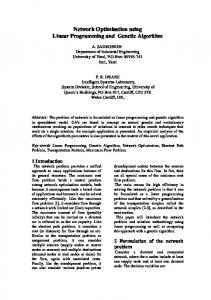
III. S IMULATION R ESULTS In this section, we provide link-level performance results for LDC examples produced by our design framework and by classic MIMO benchmark schemes, including Alamouti code [1], SM [3], Hassibi’s code [1], Gohary’s code [6] and Diagonal Algebraic Space-Time (DAST) codes [8]. For simplicity, M , N and T were set to 2. We have Q = 2 for the Alamouti/DAST code and Q = 4 for the other codes, resulting in the code rate of 4 and 8 Bits per Symbol (BPS), respectively. The standard MLD receiver and an i.i.d. Rayleigh fading channel model with perfect channel estimation were used. The Orthogonal Frequency Division Multiplexing (OFDM) system employed a frame size of 12 OFDM symbols, each consisting of 1024 subcarriers.
LDC, i.i.d. Rayleigh Channel 20
16
MI (bits/s/Hz)
14 12
5
2 -1
R=4 BPS R=8 BPS ML detector
10
5
FER
18
10
M/N/T=2/2/2 Alamouti SM New LDC Hassibi Gohary Golden DAST
2
8
-2
10
6
5
4 2
2 -3
0 0
5
10
15
20
SNR (dB) Fig. 3.
4and8bps_2rx_b20_ml_uncor_v2_fer_spl09.gle
1
M/N/T=2/2/2 Alamouti SM New LDC Hassibi Gohary Golden DAST
25
30
10
0
5
10
15
20
25
30
Eb/N0 (dB)
MI and FER performances.
In Fig. 3, the achievable Mutual Information (MI) and the corresponding Frame Error Rate (FER) performance of the different schemes are plotted, where the effective system data rates defined in Section II-A, namely R = 4 and R = 8 BPS were considered. As expected, SM is the scheme that yields the maximal achievable MI. Furthermore,
Fig. 3 shows that the new LDC, among a few others, is also capable of attaining the highest MI, while the Alamouti and DAST codes only achieve a significantly lower MI value. This result indicates that the LDC optimised by our design method is capable of reaching the best possible performance in terms of MI, and thus a high effective data throughput. Moreover, Fig. 3 shows that our optimised LDC provides a similar performance as that of the optimum Golden code [9] for both cases, demonstrating its high robustness. This proves that a near-optimum DMT is practically
Copyright (c) 2009 IEEE. Personal use is permitted. For any other purposes, Permission must be obtained from the IEEE by emailing
[email protected]. Authorized licensed use limited to: UNIVERSITY OF SOUTHAMPTON. Downloaded on February 1, 2010 at 18:15 from IEEE Xplore. Restrictions apply.
This article has been accepted for publication in a future issue of this journal, but has not been fully edited. Content may change prior to final publication. 9
achievable by LDCs generated from our optimisation framework. Specifically, we would like to point out that the proposed LDC design framework can offer more than the Golden code does. Firstly, our design method has the flexibility to produce LDCs with arbitrary dimensions for both square and non-square cases, which can not be achieved by the Golden code or its higher-order counterparts, namely the Perfect codes [10], which are square codes with fixed dimensions. Secondly, our design framework allows us to easily adapt the optimisation criteria. This is beneficial for finding optimum codes against different design targets. A combination of several criteria within a single optimisation process is also possible. IV. C ONCLUSIONS Finally, we briefly conclude that our new LDC design framework, which exploits the unitary matrix theory, is capable of exploring the entire space of unitary matrices according to the unique Haar measure. Further, the specific GA equipped with a new hybrid mutation operator provides a flexible and efficient framework for searching for new codes. We demonstrated that unitary LDCs with better performance than many known codes can be found with the aid of the proposed design method. The optimised LDCs offer both a high data rate and a high link robustness, thus achieving a near-optimum DMT, as verified by our simulation results. R EFERENCES [1] B. Hassibi and B. M. Hochwald, “High-rate codes that are linear in space and time,” IEEE Transactions on Information Theory, vol. 48, no. 7, pp. 1804–1824, July 2002. [2] R. W. Heath Jr. and A. J. Paulraj, “Linear dispersion codes for MIMO systems based on frame theory,” IEEE Transactions on Signal Processing, vol. 50, no. 10, pp. 2429–2441, October 2002. [3] G. J. Foschini, G. D. Golden, R. A. Valenzuela, and P. W. Wolniansky, “Simplified processing for high spectral efficiency wireless communication employing multi-element arrays,” IEEE Journal on Selected Areas in Communications, vol. 17, no. 11, pp. 1841–1852, November 1999. [4] S. M. Alamouti, “A Simple Transmit Diversity Technique for Wireless Communications,” IEEE Journal on Selected Areas in Communications, vol. 16, no. 8, pp. 1451–1458, October 1998. [5] V. Tarokh, H. Jafarkhani, and A. R. Calderbank, “Space-time Block Codes from Orthogonal Designs,” IEEE Transactions on Information Theory, vol. 45, no. 5, pp. 1456–1467, May 1999. [6] R. H. Gohary and T. N. Davidson, “Design of linear dispersion codes: asymptotic guidelines and their implementation,” IEEE Transactions on Wireless Communications, vol. 4, no. 6, pp. 2892–2906, November 2005. [7] X. Wang, V. Krishnamurthy, and J. Wang, “Stochastic gradient algorithms for design of minimum error-rate linear dispersion codes in MIMO wireless systems,” IEEE Transactions on Signal Processing, vol. 54, no. 4, pp. 1242–1255, April 2006. [8] M. O. Damen, K. Abed-Meraim, and J.-C. Belfiore, “Diagonal algebraic space-time block codes,” IEEE Transactions on Information Theory, vol. 48, no. 3, pp. 628–636, March 2002. [9] J.-C. Belfiore, G. Rekaya, and E. Viterbo, “The golden code: a 2 × 2 full-rate space-time code with nonvanishing determinants,” IEEE Transactions on Information Theory, vol. 51, no. 4, pp. 1432–1436, April 2005.
Copyright (c) 2009 IEEE. Personal use is permitted. For any other purposes, Permission must be obtained from the IEEE by emailing
[email protected]. Authorized licensed use limited to: UNIVERSITY OF SOUTHAMPTON. Downloaded on February 1, 2010 at 18:15 from IEEE Xplore. Restrictions apply.
This article has been accepted for publication in a future issue of this journal, but has not been fully edited. Content may change prior to final publication. 10
[10] F. Oggier, G. Rekaya, J.-C. Belfiore, and E. Viterbo, “Perfect Space-Time Block Codes,” IEEE Transactions on Information Theory, vol. 52, no. 9, pp. 3885–3902, September 2006. [11] L. Hanzo, O. R. Alamri, M. El-Hajjar, and N. Wu, Near-capacity Multi-Functional MIMOs.
IEEE Press - John Wiley & Sons Ltd.,
2009. [12] D. E. Goldberg, Genetic Algorithms in Search, Optimization, and Machine Learning. Reading, Massachusetts: Addison-Wesley, 1989. [13] M. Jiang and L. Hanzo, “Multi-User MIMO-OFDM for Next-Generation Wireless Systems,” Proceedings of the IEEE, vol. 95, no. 7, pp. 1430–1469, July 2007. [14] G. H. Golub and C. F. van Loan, Matrix Computations, 3rd ed.
Baltimore, USA: The Johns Hopkins Univ. Press, 1996.
[15] A. Hurwitz, “Ueber die Erzeugung der Invarianten durch Integration,” Nachr. Ges. Wiss. G¨ottingen Math.-Phys. Kl., vol. 1897, no. 1, pp. 71–90, March 1897. [16] M. Pozniak, K. Zyczkowski, and M. Kus, “Composed Ensembles of Random Unitary Matrices,” Journal of Physics A: Mathematical and General, vol. 31, no. 3, pp. 1059–1071, May 1998.
Copyright (c) 2009 IEEE. Personal use is permitted. For any other purposes, Permission must be obtained from the IEEE by emailing
[email protected]. Authorized licensed use limited to: UNIVERSITY OF SOUTHAMPTON. Downloaded on February 1, 2010 at 18:15 from IEEE Xplore. Restrictions apply.